EP1013080B1 - Virtual studio position sensing system - Google Patents
Virtual studio position sensing system Download PDFInfo
- Publication number
- EP1013080B1 EP1013080B1 EP98940420A EP98940420A EP1013080B1 EP 1013080 B1 EP1013080 B1 EP 1013080B1 EP 98940420 A EP98940420 A EP 98940420A EP 98940420 A EP98940420 A EP 98940420A EP 1013080 B1 EP1013080 B1 EP 1013080B1
- Authority
- EP
- European Patent Office
- Prior art keywords
- camera
- real
- led
- dimensional background
- scene
- Prior art date
- Legal status (The legal status is an assumption and is not a legal conclusion. Google has not performed a legal analysis and makes no representation as to the accuracy of the status listed.)
- Expired - Lifetime
Links
- 238000000034 method Methods 0.000 claims abstract 5
- 230000009466 transformation Effects 0.000 claims description 9
- 238000004458 analytical method Methods 0.000 claims description 6
- 238000004519 manufacturing process Methods 0.000 claims description 3
- 230000003287 optical effect Effects 0.000 claims description 3
- 238000001514 detection method Methods 0.000 claims 8
- 239000004744 fabric Substances 0.000 description 5
- 238000004364 calculation method Methods 0.000 description 4
- 239000003086 colorant Substances 0.000 description 3
- 230000003068 static effect Effects 0.000 description 2
- 230000003466 anti-cipated effect Effects 0.000 description 1
- 239000000872 buffer Substances 0.000 description 1
- 239000002131 composite material Substances 0.000 description 1
- 238000004590 computer program Methods 0.000 description 1
- 230000003111 delayed effect Effects 0.000 description 1
- 230000037431 insertion Effects 0.000 description 1
- 238000005259 measurement Methods 0.000 description 1
- 239000007787 solid Substances 0.000 description 1
- 238000001429 visible spectrum Methods 0.000 description 1
Images


Classifications
-
- H—ELECTRICITY
- H04—ELECTRIC COMMUNICATION TECHNIQUE
- H04N—PICTORIAL COMMUNICATION, e.g. TELEVISION
- H04N5/00—Details of television systems
- H04N5/222—Studio circuitry; Studio devices; Studio equipment
- H04N5/2224—Studio circuitry; Studio devices; Studio equipment related to virtual studio applications
-
- H—ELECTRICITY
- H04—ELECTRIC COMMUNICATION TECHNIQUE
- H04N—PICTORIAL COMMUNICATION, e.g. TELEVISION
- H04N5/00—Details of television systems
- H04N5/222—Studio circuitry; Studio devices; Studio equipment
-
- H—ELECTRICITY
- H04—ELECTRIC COMMUNICATION TECHNIQUE
- H04N—PICTORIAL COMMUNICATION, e.g. TELEVISION
- H04N5/00—Details of television systems
- H04N5/222—Studio circuitry; Studio devices; Studio equipment
- H04N5/262—Studio circuits, e.g. for mixing, switching-over, change of character of image, other special effects ; Cameras specially adapted for the electronic generation of special effects
- H04N5/272—Means for inserting a foreground image in a background image, i.e. inlay, outlay
Definitions
- the present invention relates to a virtual studio and in particular to a position sensing system for such a studio.
- the position of the camera is calculable by using a coded pattern on the chroma-key background. This enables the position of the camera, as well as its orientation and the lens zoom, to be continuously calculated and thereby the perspective of the virtual 3D set can be adjusted correctly to suit the camera position.
- WO95/30312 also works well providing that the background panel is a patterned chroma-key panel. However the system does not work where a normal studio or stage set with real background is used.
- the present invention provides a further object to enable actors who represent foreground objects to wear colours which would otherwise clash with normal chroma-key background panel.
- a chroma-key background panel in an arrangement such as in WO95/30312 is a combination of light and dark blue patterns in such a prior arrangement the actors cannot wear blue which is extremely restrictive.
- the actors can wear any colour and the background real set can be any colour.
- the background real set does not have to be flat.
- a plurality of LED's are positioned in a real stage set, the LED's forming a pattern which is known from an initial measurement of the position of each LED.
- the LED's preferably operate in the non-visible spectrum to be thereby non detectable by a normal video camera.
- the LED outputs are detected by a detector camera mounted on a TV camera, the pattern formed by the LED's being utilised to compute the position of the TV camera.
- the present invention therefore provides a virtual reality system for a scene having real background scenery as claimed in claim 1
- the detector device comprises a detector camera which is preferable boresighted to be aligned with the TV camera.
- the LED's are infra-red operating at a frequency outside the frequency range of the TV camera.
- each LED emits light in a coded form, thereby enabling each light source to be individually identifiable.
- the LED's are all positioned in plane or a plurality of planes.
- the real scene may be a scene painted onto a background as used in theatres or may be an actual location.
- the background scene may be any colour or combination of colours.
- a plurality of television cameras may be positioned in front of the background scene, each camera being provided with a detecting device.
- the invention further provides a method for producing a combined video image comprising a real background scene viewed by a TV camera as claimed in claim 7.
- Figure 1 shows a schematic form of a studio set 10 which comprises a backcloth 12 and possible side clothes 14,16.
- backcloths may comprise, as in stage sets normal painted backcloths or could comprise actual real objects such as stairs.
- the set is viewed by one or more cameras 20,22.
- Each first and second cameras 20,22 is provided with LED's A and B (200,220).
- First and second static cameras 30,32 are provided preferably mounted above the set as shown. They may be mounted on rails 300,320 to be adjustable longitudinally and also in angle of view.
- LED's A and B and cameras 30,32 is to identify and track the position in x,y and z planes of the cameras 20 and 22. This operation is described in the co-pending British Patent Application No. 9702636.3 to the present applicant which should be referred to with reference to the calculation of the position of cameras 20,30 relative to the set 10. The technical content of this prior application is incorporated herein by way of technical explanation.
- the "backcloth” comprises a chroma-key panel which is provided with a pattern enabling the perspective of the camera field of view relative to the panel to be continuously calculated.
- the technical content of which is incorporated herein by way of technical explanation.
- Both the prior inventions have a practical problem because both require that the background panels are chroma-key. This prevents real sets being used and also prevents actors who represent foreground objects from wearing colours which are the same as the chroma-key panels.
- the set comprises a background panel which has real views/scenes painted thereon. These are exemplified by trees 120,122.
- a plurality of further LED's 130 are positioned in the panel. If the panel is a flat panel then the LED's can be set into the surface of the panel. If the panel comprises, as in Figure 1, a rear panel 12 and two side panels 14,16 then LED's 130 are preferably positioned within such panels.
- Each LED may be identical but each LED is preferably switched in a coded sequence to thereby render its identity able to be read. Each LED preferably operates in the infra-red region to thereby not be visible to the eye or to cameras 20,22.
- Each camera 20,22 is preferably equipped with an infra-red camera 202,222 which is boresighted (i.e. aligned with the main focal axis) of the camera 20 or 22.
- the cameras 202,222 provide an image of the array of LED's 130, the number of LED's being imaged depending on the distance which the camera 20,22 is away from the panel 12,13,16.
- a plurality of LED's must to imaged. thus, if the camera 20,22 is anticipated to show only part of the panel then a larger number of LED's will be required. Generally 7 LED's are considered sufficient and therefore a panel may have between seven (7) and thirty (30) or more LED's to ensure correct alignment calculations.
- the system can also operate with a theatre set such as shown in Figures 2 and 3.
- the set comprises a generally circular stage 500 (or outdoor setting) with two pillars 502,504 and steps 506,508,510.
- the LED's 130 are positioned in a flat plane but the plane comprises portions of the steps 510 and pillars 502,504 as shown in Figure 3.
- the LED's associated with steps 510 are positioned slightly in front of the steps as shown. This is to enable a flat plane of LED's to be established even if no actual piece of scenery exists at that exact position.
- Unit 400 can switch between cameras 20,22 to provide position information for either or both cameras.
- Unit 400 buffers the input from the cameras 30,32 to provide an output to tracking unit 402 which provides on line 4022 an output signal from the overhead cameras 30,32 which is fed to a position sensing unit 404, the output of which provide on line 4042 x,y and z co-ordinates for each camera 20 or 22.
- tracking unit 402 which provides on line 4022 an output signal from the overhead cameras 30,32 which is fed to a position sensing unit 404, the output of which provide on line 4042 x,y and z co-ordinates for each camera 20 or 22.
- the outputs of cameras 202,222 comprise a map of the LED's 130 as viewed and these outputs are fed on line 4024 to a camera pan, tilt and roll computation unit 406, this unit also receiving on line 4042 the x,y and z co-ordinates.
- the output of unit 406 is fed on line 4062 to a perspective transformation unit 408 which also receives on line 4082 the zoom/focus sensor information of each camera 20,22.
- a plurality of virtual objects/animations is stored in a suitable store 410 and selected ones of these are transformed by unit 408 on line 4102 to the correct perspective to be combined with the camera output 20,22 to 'form a composite picture output such that the viewer sees the real set with real objects and also virtual objects positioned therein.
- a graphics unit 412 can also input graphical information on line 4122 to appear in the combined video output.
- Suitable control systems such as a keyboard 414 or joystick 416 can be used to control the positioning of the virtual object or graphics on the screen.
- the outputs of unit 408 are fed to a combined chroma-keyer unit 418 on lines 4082,4084 and 4086 so that the inserted virtual objects may be combined in the correct perspective, position and size with the foreground video as follows.
- each camera is fed on lines 2022, 2222 to a switcher 420 which enables the output of a selected camera 20 or 22 to be used by the producer of a program.
- the output of the selected camera fed via switcher 420 on line 422 is delayed by a delay circuit 422, the delay of which matches the delay in calculating the camera position/orientation via units 400 to 408 thereby ensuring that the foreground information and any virtual insertion information are combined together in the correct sequence in combiner unit 418.
- the advantage of the system according to the present invention is that a virtual object may be positioned within a real set because since the size and perspective of the virtual object and also its position relative to' the set are known, the virtual object can be positioned within the set. If the object is in front of a part of the set then it will obscure the set and if behind it will be obscured by the set.
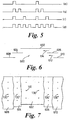
- FIG. 5 simplified digital codes are shown to illustrate a preferred embodiment. In this embodiment only four codes a), b), c) and d) are shown. Each LED is controlled by a control unit 424 to switch in accordance with a defined code.
- each LED 130 in the real set must be known and this. can be accomplished either by having camera 20 moved into a fixed known position and known focus and zoom and then calculating the position of each LED by reference to the read out of camera 202. Alternatively the LED's can be placed in known positions.
- stage set 600 comprising a main backcloth 602, first and second side (wing) cloths 604,606 and third and fourth side (wing) cloths 608, 610.
- Each cloth 602-610 may be painted as usual for a stage set.
- each cloth 602-610 a number of LED's may be positioned. Those on cloth 602 are referenced 130 and on cloths 604,606 are 130' and cloths 608,610 are 130".
- Each LED will have a coded output in the infra-red which will determine not only its position in the cloth 602,604,606,608 or 610 but also which cloth is located in.
- the computer program can determine the position of the camera by reference to LED's in more than one plane.
- two LED's 221,223 are mounted on the cameras 20,22 parallel to the optical axis 225 of the camera. Only camera 22 is described for ease of explanation. This enables the position and part/tilt of the camera to be measured.
- sensors are mounted on the lens.
- the output of lens potentiometers which are present on many standard studio lenses may be read to obtain information on the zoom/focus status of the camera/
- the outputs of the additional LED's 221,223,227,229 and 231 are preferably suitably coded to ensure correct identification by the position sensing equipment to enable the position and pan/tilt/roll of the camera to be correctly measured.
- all cameras may be so equipped.
Landscapes
- Engineering & Computer Science (AREA)
- Multimedia (AREA)
- Signal Processing (AREA)
- Studio Devices (AREA)
- Studio Circuits (AREA)
Abstract
Description
- The present invention relates to a virtual studio and in particular to a position sensing system for such a studio.
- In virtual studio systems a chroma-key background is provided in front of which an actor stands. In the TV picture seen by the viewer the chroma-key background is replaced by a virtual scene. Such a system is described in PCT Patent Application No. WO95/30312 to the present applicant.
- In the above known system the position of the camera is calculable by using a coded pattern on the chroma-key background. This enables the position of the camera, as well as its orientation and the lens zoom, to be continuously calculated and thereby the perspective of the virtual 3D set can be adjusted correctly to suit the camera position.
- This works perfectly for cameras which have a fixed focus and zoom or a fixed position but problems can be encountered in situations where the cameraman is free to simultaneously change the camera position and the lens zoom. For example, when the camera's optical axis is perpendicular (or almost perpendicular) to the patterned wall, the changes in the captured pattern due to zooming of the lens or to changing the distance of the camera from the wall are identical (or almost identical) and the system cannot extract the correct solution from the captured pattern.
- The system of WO95/30312 also works well providing that the background panel is a patterned chroma-key panel. However the system does not work where a normal studio or stage set with real background is used.
- Thus, if it is desired to position a virtual 3D object in a normal stage set this cannot be done except for a static camera because the position of the camera relative to the stage set cannot be calculated as the camera moves.
- 1. US 5,227,985 discloses a system for calculating the position and orientation of a rigid body with respect to a fixed position camera by using an array of visible light sources on the rigid body.
- 2. DE 9,418,382 discloses a system for integrating images from the same camera point of view into a single image.
- 3. WO96/32697 discloses a virtual studio set video production system in which the position and orientation of a camera is provided by a magnetic tracker system.
-
- It is a first object of the present invention to enable the position of a camera to be calculated in a normal stage set in which the stage set may comprise a real background.
- It is a further object to enable virtual 3D objects to be positioned in a normal stage set.
- The present invention provides a further object to enable actors who represent foreground objects to wear colours which would otherwise clash with normal chroma-key background panel. Thus, assuming that a chroma-key background panel in an arrangement such as in WO95/30312 is a combination of light and dark blue patterns in such a prior arrangement the actors cannot wear blue which is extremely restrictive.
- In the present invention the actors can wear any colour and the background real set can be any colour.
- The background real set does not have to be flat.
- In accordance with the present invention a plurality of LED's are positioned in a real stage set, the LED's forming a pattern which is known from an initial measurement of the position of each LED.
- The LED's preferably operate in the non-visible spectrum to be thereby non detectable by a normal video camera.
- The LED outputs are detected by a detector camera mounted on a TV camera, the pattern formed by the LED's being utilised to compute the position of the TV camera.
- The present invention therefore provides a virtual reality system for a scene having real background scenery as claimed in
claim 1 - Preferably the detector device comprises a detector camera which is preferable boresighted to be aligned with the TV camera..
- In a preferred embodiment the LED's are infra-red operating at a frequency outside the frequency range of the TV camera.
- Preferably each LED emits light in a coded form, thereby enabling each light source to be individually identifiable.
- Preferably the LED's are all positioned in plane or a plurality of planes.
- The real scene may be a scene painted onto a background as used in theatres or may be an actual location.
- The background scene may be any colour or combination of colours.
- A plurality of television cameras may be positioned in front of the background scene, each camera being provided with a detecting device.
- The invention further provides a method for producing a combined video image comprising a real background scene viewed by a TV camera as claimed in claim 7.
- Embodiments of the present invention will now be described with reference to the accompanying drawings in which :
- Figure 1 shows schematically a real background scene with two cameras positioned to photograph or video the background scene;
- Figure 2 shows an alternative schematic design of studio set in plan view;
- Figure 3 shows the studio set of Figure 3 in elevation;
- Figure 4 shows in block diagrammatic form circuitry suitable for the two camera system of Figure 1;
- Figure 5 shows coding sequences suitable for the LED's;
- Figure 6 shows the scene of Figure 4 in plan view; and
- Figure 7 shows an alternative background scene in elevation.
-
- With reference now to the drawings, Figure 1 shows a schematic form of a
studio set 10 which comprises abackcloth 12 andpossible side clothes 14,16. These backcloths may comprise, as in stage sets normal painted backcloths or could comprise actual real objects such as stairs. - In the embodiment of Figure 1 the set is assumed to comprise flat back and side clothes but as may be seen, with reference to Figures 2 and 3, real sets with solid objects may be used.
- With reference to Figure 1, the set is viewed by one or
more cameras second cameras - First and second
static cameras - The operation of LED's A and B and
cameras cameras cameras set 10. The technical content of this prior application is incorporated herein by way of technical explanation. - In this co-pending patent application, as well as in PCT No. WO95/30312, the "backcloth" comprises a chroma-key panel which is provided with a pattern enabling the perspective of the camera field of view relative to the panel to be continuously calculated. With respect to the calculation of perspective, reference is made to PCT No. WO95/30312, the technical content of which is incorporated herein by way of technical explanation.
- Both the prior inventions have a practical problem because both require that the background panels are chroma-key. This prevents real sets being used and also prevents actors who represent foreground objects from wearing colours which are the same as the chroma-key panels.
- In the present invention, as shown in Figure 1, the set comprises a background panel which has real views/scenes painted thereon. These are exemplified by trees 120,122.
- In the present invention a plurality of further LED's 130 are positioned in the panel. If the panel is a flat panel then the LED's can be set into the surface of the panel. If the panel comprises, as in Figure 1, a
rear panel 12 and twoside panels 14,16 then LED's 130 are preferably positioned within such panels. - Each LED may be identical but each LED is preferably switched in a coded sequence to thereby render its identity able to be read. Each LED preferably operates in the infra-red region to thereby not be visible to the eye or to
cameras - Each
camera camera camera panel - In order to be able to correctly analyse the position and perspective of
camera camera - The system can also operate with a theatre set such as shown in Figures 2 and 3.
- In Figures 2 and 3 the set comprises a generally circular stage 500 (or outdoor setting) with two pillars 502,504 and steps 506,508,510.
- The LED's 130 are positioned in a flat plane but the plane comprises portions of the
steps 510 and pillars 502,504 as shown in Figure 3. - With reference to Figure 2, the LED's associated with
steps 510 are positioned slightly in front of the steps as shown. This is to enable a flat plane of LED's to be established even if no actual piece of scenery exists at that exact position. - It is also possible to position LED's on the side steps 506,508 providing the angle between the side steps and the main plane of LED's found by 502,504 and
steps 510 is known. By angular mathematical analysis the position of the LED's 130 in both planes can be determined as can also be the case for LED's insteps 508. - Thus, in the case of Figures 1 and 2,3 there can be positioned virtual objects such as table 132, chairs 134,136 (Figure 1) or a
car 138 as in Figure 3. It is equally possible to position animated objects or displays in selected positions and for these to move naturally into new positions ascameras - With reference now to Figure 4, the inputs from
cameras 30,32,202,222 are fed to acomputer unit 400 and to atracking unit 402.Unit 400 can switch betweencameras -
Unit 400 buffers the input from thecameras unit 402 which provides online 4022 an output signal from theoverhead cameras position sensing unit 404, the output of which provide on line 4042 x,y and z co-ordinates for eachcamera - The outputs of cameras 202,222 comprise a map of the LED's 130 as viewed and these outputs are fed on
line 4024 to a camera pan, tilt and rollcomputation unit 406, this unit also receiving online 4042 the x,y and z co-ordinates. The output ofunit 406 is fed online 4062 to aperspective transformation unit 408 which also receives online 4082 the zoom/focus sensor information of eachcamera - A plurality of virtual objects/animations is stored in a
suitable store 410 and selected ones of these are transformed byunit 408 online 4102 to the correct perspective to be combined with thecamera output graphics unit 412 can also input graphical information online 4122 to appear in the combined video output. Suitable control systems such as akeyboard 414 orjoystick 416 can be used to control the positioning of the virtual object or graphics on the screen. The outputs ofunit 408 are fed to a combined chroma-keyer unit 418 onlines - The output of each camera is fed on
lines switcher 420 which enables the output of a selectedcamera switcher 420 online 422 is delayed by adelay circuit 422, the delay of which matches the delay in calculating the camera position/orientation viaunits 400 to 408 thereby ensuring that the foreground information and any virtual insertion information are combined together in the correct sequence incombiner unit 418. - The advantage of the system according to the present invention is that a virtual object may be positioned within a real set because since the size and perspective of the virtual object and also its position relative to' the set are known, the virtual object can be positioned within the set. If the object is in front of a part of the set then it will obscure the set and if behind it will be obscured by the set.
- Referring now to Figure 5, simplified digital codes are shown to illustrate a preferred embodiment. In this embodiment only four codes a), b), c) and d) are shown. Each LED is controlled by a
control unit 424 to switch in accordance with a defined code. - In Figure 5 four digital codes are shown 10000000, 10100000, 10010000 and 101010100. Obviously other combinations can be selected to provide for a plurality of LED's, all of which are identifiable by
unit 400. - The position of each
LED 130 in the real set must be known and this. can be accomplished either by havingcamera 20 moved into a fixed known position and known focus and zoom and then calculating the position of each LED by reference to the read out ofcamera 202. Alternatively the LED's can be placed in known positions. - With reference to Figures 6 and 7, the advantage of the present invention can be seen with a
stage set 600 comprising amain backcloth 602, first and second side (wing) cloths 604,606 and third and fourth side (wing) cloths 608, 610. - Each cloth 602-610 may be painted as usual for a stage set.
- On each cloth 602-610 a number of LED's may be positioned. Those on
cloth 602 are referenced 130 and on cloths 604,606 are 130' and cloths 608,610 are 130". - Each LED will have a coded output in the infra-red which will determine not only its position in the cloth 602,604,606,608 or 610 but also which cloth is located in. Thus, the computer program can determine the position of the camera by reference to LED's in more than one plane.
- An advantage here is that actors can enter and exit from the wings via openings indicated by
arrows 612;614 in the normal manner and virtual objects can also be made to enter and exit. Therefore the system is far more versatile than the previous known chroma-key system. - In a further embodiment, as illustrated in Figure 1, two LED's 221,223 are mounted on the
cameras optical axis 225 of the camera.Only camera 22 is described for ease of explanation. This enables the position and part/tilt of the camera to be measured. - To obtain information on the zoom and focus of the camera, sensors are mounted on the lens. Alternatively, the output of lens potentiometers which are present on many standard studio lenses may be read to obtain information on the zoom/focus status of the camera/
- Additionally, by mounting three further LED's 227,229,231 on the camera in a triangle, the-roll of the camera can be detected, thus allowing shoulder mounted cameras to be used.
- The outputs of the additional LED's 221,223,227,229 and 231 are preferably suitably coded to ensure correct identification by the position sensing equipment to enable the position and pan/tilt/roll of the camera to be correctly measured.
- If more than one camera is used, then all cameras may be so equipped.
Claims (7)
- A virtual reality system for a scene having real three dimensional background scenery, said system comprising a television camera (20) providing a video output of said scene, an auxiliary detection device (202) mounted on said television camera (20), wherein in said system a plurality of light emitting devices (LED's) (130) is mounted in known fixed positions on relevant parts of said real three dimensional background scenery or in known fixed relationship relative to said relevant parts of said real three dimensional background scenery to form a defined array and including electronic detection means (402, 406, 408) connected to said detection device, said detection means comprising position sensing analysis means (408) for analysing the perspective of the defined array, as detected by said detector device, to provide a positional read out defining the position of said television camera (20) relative to the real three dimensional background scenery and defining the position of each LED of said plurality of LEDs relative to said TV camera thereby defining the position of each of said relevant parts of said real three dimensional background scenery and comprising a virtual object store (410), a perspective transformation unit and a combiner unit (418) in which the positional read out from the position sensing analysis means is connected to said perspective transformation unit to provide a transformation value, in which the virtual object store is connected to said combiner unit via said perspective transformation unit to transform the perspective and size of a virtual object to be inserted into said combiner unit and in which the video output of the scene provided by said TV camera is connected to said combiner circuit and in which the combiner circuit provides as an output a combined video image in which the virtual object is positioned in said scene and is moveable in said real three dimensional background scene, relative to said camera, in such a manner as to be able to be realistically seen by a viewer to appear in front of or behind a part of said real three dimensional background scenery and to be obscured by a part of said real three dimensional background scenery as would be the case if said virtual object were actually a real object included in said real three dimensional background scenery, in which the auxiliary detector device (202) comprises a detector camera which is boresighted to be aligned with the camera (20), in which the LED's (130) are infra-red operating at a frequency outside the frequency range of the camera and in which each LED (130) emits light in a coded form, thereby enabling each light source to be individually identifiable.
- A camera positioning system as claimed in claim 1 in which the LED's (130) are all positioned in plane or a plurality of planes.
- A camera positioning system as claimed in claim 2 in which the real scene (12) is a scene painted onto a background as used in theatres or is an actual location.
- A camera positioning system as claimed in any one of claims 1 to 3 in which a plurality of television cameras (20, 22) are positioned in front of the background scene, each camera being provided with a detecting device (202, 222).
- A camera positioning system as claimed in any one of claims 1 to 4 further comprising two LED's (221, 223) mounted on each camera in positions parallel to the optical axis of the camera to enable the position and pan/tilt of each camera to be measured.
- A camera positioning system as claimed in any one of claims 1 to 5 in which three further LED's (227, 229, 231) are mounted on each camera in a triangle to enable the roll of the camera to be measured.
- A method for producing a combined video image comprising a real three dimensional background scene viewed by a television camera (20) providing a video output of said scene, an auxiliary detection device (202) mounted on said television camera (20), wherein said method includes positioning a plurality of light emitting devices (LED's) (130) to be mounted in known fixed positions on relevant parts of said real three dimensional background scenery or in known fixed relationship relative to said relevant parts of said real three dimensional background scenery to form a defined array and including electronic detection means (402, 406, 408) connected to said detection device, in which in said method, said detection means comprises position sensing analysis means (408) for analysing the perspective of the defined array, as detected by said detector device, to provide a positional read out defining the position of said television camera (20) relative to the real three dimensional background scenery and defining the position of each LED of said plurality of LEDs relative to said TV camera thereby defining the position of each of said relevant parts of said real three dimensional background scenery and comprising a virtual object store (410), a perspective transformation unit and a combiner unit (418) in which the positional read out from the position sensing analysis means is connected to said perspective transformation unit to provide a transformation value, in which the virtual object store is connected to said combiner unit via said perspective transformation unit to transform the perspective and size of a virtual object to be inserted into said combiner unit and in which the video output of the scene provided by said TV camera is connected to said combiner circuit in which in said method the combiner circuit provides as an output a combined video image and in which in said method the virtual object is positioned in said scene and is moveable in said real three dimensional background scene, relative to said camera, in such a manner as to be able to be realistically seen by a viewer to appear in front of or behind one or more of said relevant parts of said real three dimensional background scenery and to be occluded by said one or more parts of said real three dimensional background scenery as would be the case if said virtual object were actually a real object included in said real three dimensional background scenery, in which the auxiliary detector device (202) comprises a detector camera which is boresighted to be aligned with the camera (20),in which the LED's (130) are infra-red operating at a frequency outside the frequency range of the camera and in which each LED (130) emits light in a coded form, thereby enabling each light source to be individually identifiable.
Applications Claiming Priority (3)
| Application Number | Priority Date | Filing Date | Title |
|---|---|---|---|
| GB9719379 | 1997-09-12 | ||
| GB9719379A GB2329292A (en) | 1997-09-12 | 1997-09-12 | Camera position sensing system |
| PCT/GB1998/002595 WO1999014939A1 (en) | 1997-09-12 | 1998-08-28 | Virtual studio position sensing system |
Publications (2)
| Publication Number | Publication Date |
|---|---|
| EP1013080A1 EP1013080A1 (en) | 2000-06-28 |
| EP1013080B1 true EP1013080B1 (en) | 2003-10-22 |
Family
ID=10818942
Family Applications (1)
| Application Number | Title | Priority Date | Filing Date |
|---|---|---|---|
| EP98940420A Expired - Lifetime EP1013080B1 (en) | 1997-09-12 | 1998-08-28 | Virtual studio position sensing system |
Country Status (6)
| Country | Link |
|---|---|
| US (1) | US6559884B1 (en) |
| EP (1) | EP1013080B1 (en) |
| AU (1) | AU8874998A (en) |
| DE (1) | DE69819181T2 (en) |
| GB (1) | GB2329292A (en) |
| WO (1) | WO1999014939A1 (en) |
Cited By (1)
| Publication number | Priority date | Publication date | Assignee | Title |
|---|---|---|---|---|
| KR20210142722A (en) * | 2019-03-29 | 2021-11-25 | 글로보 코무니카상 이 파르티시파소이 에스.에이. | Systems for capturing and projecting images, uses of the systems, and methods of capturing, projecting and embedding images |
Families Citing this family (32)
| Publication number | Priority date | Publication date | Assignee | Title |
|---|---|---|---|---|
| AU2834899A (en) * | 1998-02-18 | 1999-09-06 | Gmd-Forschungszentrum Informationstechnik Gmbh | Camera tracking system for a virtual television or video studio |
| WO1999066717A1 (en) * | 1998-06-16 | 1999-12-23 | Limat Ag | Transmission device for transmitting image contents in a concealed manner |
| US6381362B1 (en) * | 1999-04-08 | 2002-04-30 | Tata America International Corporation | Method and apparatus for including virtual ads in video presentations |
| US6965397B1 (en) | 1999-11-22 | 2005-11-15 | Sportvision, Inc. | Measuring camera attitude |
| EP1189171A2 (en) * | 2000-09-08 | 2002-03-20 | Fraunhofer-Gesellschaft zur Förderung der angewandten Forschung e.V. | Method and apparatus for generating picture in a virtual studio |
| SE0003373L (en) * | 2000-09-20 | 2002-01-29 | Jan G Faeger | Method and apparatus for producing information about an environment and use of the apparatus |
| JP4136859B2 (en) * | 2003-01-10 | 2008-08-20 | キヤノン株式会社 | Position and orientation measurement method |
| CN100399799C (en) * | 2004-08-24 | 2008-07-02 | 西安宏源视讯设备有限责任公司 | A Relay Tracking Method of Auxiliary Camera Light Graphics in Virtual Studio System |
| GB2418482A (en) * | 2004-09-23 | 2006-03-29 | Wayne Howell | Method for locating luminaires using optical feedback |
| WO2006135358A1 (en) * | 2005-06-08 | 2006-12-21 | Thomson Licensing | Method, apparatus and system for alternate image/video insertion |
| US8933967B2 (en) * | 2005-07-14 | 2015-01-13 | Charles D. Huston | System and method for creating and sharing an event using a social network |
| US11972450B2 (en) | 2005-07-14 | 2024-04-30 | Charles D. Huston | Spectator and participant system and method for displaying different views of an event |
| US9344842B2 (en) | 2005-07-14 | 2016-05-17 | Charles D. Huston | System and method for viewing golf using virtual reality |
| US8207843B2 (en) | 2005-07-14 | 2012-06-26 | Huston Charles D | GPS-based location and messaging system and method |
| FR2889753A1 (en) * | 2005-08-09 | 2007-02-16 | Total Immersion Sa | SYSTEM FOR USER TO VIEW A VIRTUAL COCKPIT IN A VIDEO ENVIRONMENT |
| US7689062B2 (en) * | 2006-07-16 | 2010-03-30 | Seambi Ltd. | System and method for virtual content placement |
| US20080117333A1 (en) * | 2006-11-17 | 2008-05-22 | Disney Enterprises, Inc. | Method, System And Computer Program Product For Video Insertion |
| US20090153550A1 (en) * | 2007-12-18 | 2009-06-18 | Disney Enterprises, Inc. | Virtual object rendering system and method |
| GB2456802A (en) * | 2008-01-24 | 2009-07-29 | Areograph Ltd | Image capture and motion picture generation using both motion camera and scene scanning imaging systems |
| TW201110928A (en) * | 2009-09-16 | 2011-04-01 | Univ Chang Gung | Optical tracking apparatus and its positioning method |
| US8786415B2 (en) * | 2010-02-24 | 2014-07-22 | Sportvision, Inc. | Tracking system using proximity and/or presence |
| EP2715708A1 (en) * | 2011-05-25 | 2014-04-09 | Koninklijke Philips N.V. | An identification system for a surface |
| CN102752488B (en) * | 2011-08-02 | 2017-08-04 | 新奥特(北京)视频技术有限公司 | Realize the method being uniformly controlled, equipment and the system of multi-studio system |
| US9215383B2 (en) | 2011-08-05 | 2015-12-15 | Sportsvision, Inc. | System for enhancing video from a mobile camera |
| JP2013127774A (en) * | 2011-11-16 | 2013-06-27 | Canon Inc | Image processing device, image processing method, and program |
| DE102012107153A1 (en) | 2012-08-03 | 2014-02-27 | Hendrik Fehlis | Device and method for determining the self-position of an image-receiving camera |
| FR3034940B1 (en) * | 2015-04-10 | 2018-04-13 | Solidanim | SYSTEM AND METHOD FOR TURNING VIDEO FILM, AND ENVIRONMENT USED |
| CN106969733B (en) * | 2016-05-20 | 2021-05-14 | 美国西北仪器公司 | Method for positioning target object in target space and distance measuring device |
| DE102017208526A1 (en) * | 2017-05-19 | 2018-11-22 | Signum Bildtechnik GmbH | Marker based camera tracker |
| US10675536B2 (en) * | 2018-10-03 | 2020-06-09 | Song Chen | Gaming system that alters target images produced by an LED array |
| KR101961844B1 (en) * | 2018-11-29 | 2019-03-25 | (주)인더텍 | Augment reality based occupational therapy table device for cognitive training and occupational therapy method |
| DE102021106488A1 (en) | 2020-12-23 | 2022-06-23 | Arnold & Richter Cine Technik Gmbh & Co. Betriebs Kg | Background display device, background display system, recording system, camera system, digital camera and method for controlling a background display device |
Family Cites Families (13)
| Publication number | Priority date | Publication date | Assignee | Title |
|---|---|---|---|---|
| US4866626A (en) * | 1987-09-18 | 1989-09-12 | Egli Werner H | Navigation by a video-camera sensed ground array |
| IL88263A (en) * | 1988-11-02 | 1993-03-15 | Electro Optics Ind Ltd | Navigation system |
| US5227985A (en) * | 1991-08-19 | 1993-07-13 | University Of Maryland | Computer vision system for position monitoring in three dimensions using non-coplanar light sources attached to a monitored object |
| GB9121707D0 (en) * | 1991-10-12 | 1991-11-27 | British Aerospace | Improvements in computer-generated imagery |
| GB2272343A (en) * | 1992-11-10 | 1994-05-11 | Gec Ferranti Defence Syst | Automatic aircraft landing system calibration |
| IL109487A (en) * | 1994-04-29 | 1996-09-12 | Orad Hi Tec Systems Ltd | Chromakeying system |
| DE9418382U1 (en) * | 1994-11-16 | 1996-03-21 | Smit, Michael, 50997 Köln | Mixed image generator |
| AU5446896A (en) * | 1995-04-10 | 1996-10-30 | Electrogig Corporation | Hand-held camera tracking for virtual set video production s ystem |
| DE19521600A1 (en) * | 1995-06-14 | 1996-12-19 | Bodenseewerk Geraetetech | Landing procedures for unmanned aerial vehicles |
| GB2305050A (en) * | 1995-09-08 | 1997-03-26 | Orad Hi Tec Systems Ltd | Determining the position of a television camera for use in a virtual studio employing chroma keying |
| JP3359241B2 (en) * | 1995-10-13 | 2002-12-24 | 日本電信電話株式会社 | Imaging method and apparatus |
| US5889550A (en) * | 1996-06-10 | 1999-03-30 | Adaptive Optics Associates, Inc. | Camera tracking system |
| US6310644B1 (en) * | 1997-03-26 | 2001-10-30 | 3Dm Devices Inc. | Camera theodolite system |
-
1997
- 1997-09-12 GB GB9719379A patent/GB2329292A/en not_active Withdrawn
-
1998
- 1998-08-28 WO PCT/GB1998/002595 patent/WO1999014939A1/en not_active Ceased
- 1998-08-28 EP EP98940420A patent/EP1013080B1/en not_active Expired - Lifetime
- 1998-08-28 DE DE69819181T patent/DE69819181T2/en not_active Expired - Fee Related
- 1998-08-28 AU AU88749/98A patent/AU8874998A/en not_active Abandoned
- 1998-09-04 US US09/148,566 patent/US6559884B1/en not_active Expired - Fee Related
Cited By (2)
| Publication number | Priority date | Publication date | Assignee | Title |
|---|---|---|---|---|
| KR20210142722A (en) * | 2019-03-29 | 2021-11-25 | 글로보 코무니카상 이 파르티시파소이 에스.에이. | Systems for capturing and projecting images, uses of the systems, and methods of capturing, projecting and embedding images |
| EP3952267A4 (en) * | 2019-03-29 | 2022-11-30 | Globo Comunicacao e Participacoes S.A. | SYSTEM AND METHOD OF CAPTURE AND PROJECTION OF IMAGES AND USE OF THE SYSTEM |
Also Published As
| Publication number | Publication date |
|---|---|
| DE69819181D1 (en) | 2003-11-27 |
| US6559884B1 (en) | 2003-05-06 |
| AU8874998A (en) | 1999-04-05 |
| GB2329292A (en) | 1999-03-17 |
| WO1999014939A1 (en) | 1999-03-25 |
| DE69819181T2 (en) | 2004-08-12 |
| GB9719379D0 (en) | 1997-11-12 |
| EP1013080A1 (en) | 2000-06-28 |
Similar Documents
| Publication | Publication Date | Title |
|---|---|---|
| US6559884B1 (en) | Virtual studio position sensing system | |
| CA2231374C (en) | Method and apparatus for automatic electronic replacement of billboards in a video image | |
| EP2161925B1 (en) | Method and system for fusing video streams | |
| EP0956709B1 (en) | Virtual studio position sensing system | |
| US9756277B2 (en) | System for filming a video movie | |
| US7136090B1 (en) | Communications system | |
| KR101551800B1 (en) | Surveying instrument | |
| US20110149074A1 (en) | Portable multi-view image acquisition system and multi-view image preprocessing method | |
| US20120013711A1 (en) | Method and system for creating three-dimensional viewable video from a single video stream | |
| KR102743306B1 (en) | System for image capture and projection, use of the system, and methods for capturing, projecting and inserting images | |
| IL109487A (en) | Chromakeying system | |
| EP0878099B1 (en) | Chroma keying studio system | |
| GB2305051A (en) | Automatic electronic replacement of billboards in a video image | |
| Vieira et al. | A camera-projector system for real-time 3d video | |
| EP1219115A2 (en) | Narrow bandwidth broadcasting system | |
| GB2399248A (en) | Projection of supplementary image data onto a studio set | |
| KR20050015737A (en) | Real image synthetic process by illumination control | |
| GB2386489A (en) | Virtual studio system | |
| GB2324429A (en) | Electronic zoom control in a virtual studio | |
| WO2024118828A1 (en) | Apparatus and method for real-time three dimensional imaging | |
| Kasim et al. | Glasses-free Autostereoscopic Viewing on Laptop through Spatial Tracking | |
| Thomas | Virtual Graphics for Broadcast Production | |
| JPH10126690A (en) | Studio device | |
| WO2024185485A1 (en) | Video processing device, video processing method, and program | |
| Tan | Virtual imaging in sports broadcasting: an overview |
Legal Events
| Date | Code | Title | Description |
|---|---|---|---|
| PUAI | Public reference made under article 153(3) epc to a published international application that has entered the european phase |
Free format text: ORIGINAL CODE: 0009012 |
|
| 17P | Request for examination filed |
Effective date: 20000407 |
|
| AK | Designated contracting states |
Kind code of ref document: A1 Designated state(s): DE FR GB IT |
|
| 17Q | First examination report despatched |
Effective date: 20000912 |
|
| GRAH | Despatch of communication of intention to grant a patent |
Free format text: ORIGINAL CODE: EPIDOS IGRA |
|
| GRAS | Grant fee paid |
Free format text: ORIGINAL CODE: EPIDOSNIGR3 |
|
| GRAA | (expected) grant |
Free format text: ORIGINAL CODE: 0009210 |
|
| AK | Designated contracting states |
Kind code of ref document: B1 Designated state(s): DE FR GB IT |
|
| REG | Reference to a national code |
Ref country code: GB Ref legal event code: FG4D |
|
| REF | Corresponds to: |
Ref document number: 69819181 Country of ref document: DE Date of ref document: 20031127 Kind code of ref document: P |
|
| ET | Fr: translation filed | ||
| PLBE | No opposition filed within time limit |
Free format text: ORIGINAL CODE: 0009261 |
|
| STAA | Information on the status of an ep patent application or granted ep patent |
Free format text: STATUS: NO OPPOSITION FILED WITHIN TIME LIMIT |
|
| 26N | No opposition filed |
Effective date: 20040723 |
|
| PGFP | Annual fee paid to national office [announced via postgrant information from national office to epo] |
Ref country code: DE Payment date: 20080912 Year of fee payment: 11 |
|
| PGFP | Annual fee paid to national office [announced via postgrant information from national office to epo] |
Ref country code: IT Payment date: 20080829 Year of fee payment: 11 Ref country code: FR Payment date: 20080903 Year of fee payment: 11 |
|
| PGFP | Annual fee paid to national office [announced via postgrant information from national office to epo] |
Ref country code: GB Payment date: 20080903 Year of fee payment: 11 |
|
| GBPC | Gb: european patent ceased through non-payment of renewal fee |
Effective date: 20090828 |
|
| REG | Reference to a national code |
Ref country code: FR Ref legal event code: ST Effective date: 20100430 |
|
| PG25 | Lapsed in a contracting state [announced via postgrant information from national office to epo] |
Ref country code: FR Free format text: LAPSE BECAUSE OF NON-PAYMENT OF DUE FEES Effective date: 20090831 Ref country code: DE Free format text: LAPSE BECAUSE OF NON-PAYMENT OF DUE FEES Effective date: 20100302 |
|
| PG25 | Lapsed in a contracting state [announced via postgrant information from national office to epo] |
Ref country code: GB Free format text: LAPSE BECAUSE OF NON-PAYMENT OF DUE FEES Effective date: 20090828 |
|
| PG25 | Lapsed in a contracting state [announced via postgrant information from national office to epo] |
Ref country code: IT Free format text: LAPSE BECAUSE OF NON-PAYMENT OF DUE FEES Effective date: 20090828 |