EP1013003B1 - Method for channel evaluation using receive signals transmitted via a radio channel - Google Patents
Method for channel evaluation using receive signals transmitted via a radio channel Download PDFInfo
- Publication number
- EP1013003B1 EP1013003B1 EP98928071A EP98928071A EP1013003B1 EP 1013003 B1 EP1013003 B1 EP 1013003B1 EP 98928071 A EP98928071 A EP 98928071A EP 98928071 A EP98928071 A EP 98928071A EP 1013003 B1 EP1013003 B1 EP 1013003B1
- Authority
- EP
- European Patent Office
- Prior art keywords
- signals
- subscriber
- doa
- arrival
- directionally selective
- Prior art date
- Legal status (The legal status is an assumption and is not a legal conclusion. Google has not performed a legal analysis and makes no representation as to the accuracy of the status listed.)
- Expired - Lifetime
Links
- 238000000034 method Methods 0.000 title claims description 40
- 238000011156 evaluation Methods 0.000 title description 3
- 238000012549 training Methods 0.000 claims description 17
- 230000002452 interceptive effect Effects 0.000 claims description 7
- 239000011159 matrix material Substances 0.000 claims description 7
- 238000012935 Averaging Methods 0.000 claims description 5
- 230000036961 partial effect Effects 0.000 description 20
- 238000001514 detection method Methods 0.000 description 18
- 230000005540 biological transmission Effects 0.000 description 5
- 238000010586 diagram Methods 0.000 description 5
- 238000007476 Maximum Likelihood Methods 0.000 description 4
- 238000004891 communication Methods 0.000 description 4
- 238000000926 separation method Methods 0.000 description 4
- 230000001413 cellular effect Effects 0.000 description 3
- 230000008859 change Effects 0.000 description 3
- 238000012546 transfer Methods 0.000 description 3
- 239000000969 carrier Substances 0.000 description 2
- 238000006243 chemical reaction Methods 0.000 description 2
- 238000011161 development Methods 0.000 description 2
- 230000018109 developmental process Effects 0.000 description 2
- 238000010295 mobile communication Methods 0.000 description 2
- 230000008569 process Effects 0.000 description 2
- 238000012545 processing Methods 0.000 description 2
- 230000005855 radiation Effects 0.000 description 2
- 238000001228 spectrum Methods 0.000 description 2
- 230000036962 time dependent Effects 0.000 description 2
- 238000005034 decoration Methods 0.000 description 1
- 239000006185 dispersion Substances 0.000 description 1
- 238000012423 maintenance Methods 0.000 description 1
- 238000011084 recovery Methods 0.000 description 1
- 230000009467 reduction Effects 0.000 description 1
- 238000005070 sampling Methods 0.000 description 1
- 230000002123 temporal effect Effects 0.000 description 1
Images


Classifications
-
- H—ELECTRICITY
- H04—ELECTRIC COMMUNICATION TECHNIQUE
- H04B—TRANSMISSION
- H04B7/00—Radio transmission systems, i.e. using radiation field
- H04B7/02—Diversity systems; Multi-antenna system, i.e. transmission or reception using multiple antennas
- H04B7/04—Diversity systems; Multi-antenna system, i.e. transmission or reception using multiple antennas using two or more spaced independent antennas
- H04B7/08—Diversity systems; Multi-antenna system, i.e. transmission or reception using multiple antennas using two or more spaced independent antennas at the receiving station
- H04B7/0837—Diversity systems; Multi-antenna system, i.e. transmission or reception using multiple antennas using two or more spaced independent antennas at the receiving station using pre-detection combining
- H04B7/0842—Weighted combining
- H04B7/086—Weighted combining using weights depending on external parameters, e.g. direction of arrival [DOA], predetermined weights or beamforming
-
- H—ELECTRICITY
- H04—ELECTRIC COMMUNICATION TECHNIQUE
- H04B—TRANSMISSION
- H04B7/00—Radio transmission systems, i.e. using radiation field
- H04B7/02—Diversity systems; Multi-antenna system, i.e. transmission or reception using multiple antennas
- H04B7/04—Diversity systems; Multi-antenna system, i.e. transmission or reception using multiple antennas using two or more spaced independent antennas
- H04B7/08—Diversity systems; Multi-antenna system, i.e. transmission or reception using multiple antennas using two or more spaced independent antennas at the receiving station
- H04B7/0837—Diversity systems; Multi-antenna system, i.e. transmission or reception using multiple antennas using two or more spaced independent antennas at the receiving station using pre-detection combining
- H04B7/0842—Weighted combining
- H04B7/0845—Weighted combining per branch equalization, e.g. by an FIR-filter or RAKE receiver per antenna branch
-
- H—ELECTRICITY
- H04—ELECTRIC COMMUNICATION TECHNIQUE
- H04B—TRANSMISSION
- H04B7/00—Radio transmission systems, i.e. using radiation field
- H04B7/02—Diversity systems; Multi-antenna system, i.e. transmission or reception using multiple antennas
- H04B7/04—Diversity systems; Multi-antenna system, i.e. transmission or reception using multiple antennas using two or more spaced independent antennas
- H04B7/08—Diversity systems; Multi-antenna system, i.e. transmission or reception using multiple antennas using two or more spaced independent antennas at the receiving station
- H04B7/0837—Diversity systems; Multi-antenna system, i.e. transmission or reception using multiple antennas using two or more spaced independent antennas at the receiving station using pre-detection combining
- H04B7/0842—Weighted combining
- H04B7/0848—Joint weighting
- H04B7/0851—Joint weighting using training sequences or error signal
Definitions
- the invention relates to a method for channel estimation Received signals transmitted over a radio channel, which advantageously can be used in mobile radio systems.
- a mobile radio system In a mobile radio system are from a sending radio station information about a received radio station transfer. This information reaches the received one Radio station in the form of reception signals. Through various The received signals reach the receiving signals due to external influences Radio station over several routes. The different Appropriate signal components on the paths at the receiving radio station in the form of partial waves successive times. In the receiving Radio station there is now the problem, these signal components, which are also influenced by other interference components can equalize, correct the mistakes and the decode transmitted information.
- US-A-5,299,148 discloses therein Related a method of estimation the direction of incidence of a received one Signals as well as for signal recovery under interference (interference, ranches).
- the object of the invention is a method for channel estimation to indicate that an improved resistance to interference Determination of channel impulse responses enabled.
- the task is by the method according to the features of claim 1 solved.
- Advantageous developments of the invention can be found in the subclaims.
- the number is Ka of the reception sensors is greater than the number Kd of the ones to be evaluated Partial waves per participant, so that according to the invention Ka-Kd method determined fewer channel impulse responses Need to become. This also results in a reduction in effort in channel estimation.
- the directionally selective channel impulse responses from which the individual transmitter Training sequences forming fine structures of the subscriber signals determined is a more accurate channel estimate than with in the receiving device data still to be detected possible.
- the procedure in existing mobile radio systems easy to implement.
- Another advantageous embodiment provides that the subscriber signals of several transmitters or reflectors at the Receiving device superimposed on the received signals arrive, these signals simultaneously in a frequency channel be transmitted.
- the separation of the subscriber signals can be based on a CDMA procedure (Code Division Multiple access).
- CDMA procedure Code Division Multiple access
- subscriber signal-related Channel estimation can also be used in CDMA mobile radio systems the accuracy of the channel impulse responses determined be improved.
- Such high-resolution direction estimation methods such as MUSIC (Multiple Signal Classification) or ESPRIT (Estimation of Signal Parameters via Rotational Invariance Techniques) procedures, use knowledge of complex radiation characteristics the reception sensors or certain geometrical ones Requirements for the arrangement of the reception sensors, to be accurate and with little signal processing effort make directional estimate.
- MUSIC Multiple Signal Classification
- ESPRIT Estimat of Signal Parameters via Rotational Invariance Techniques
- Resistance to interferers is further improved by additional to determine the directions of incidence of the partial waves Information about at least one direction of incidence and / or a correlation matrix of interference signals is taken into account become.
- Channel impulse responses determined from the received signals and from the non-directionally selective channel impulse responses determines the direction of incidence of at least one partial wave becomes.
- the directional signals not determined for Ka received signals Channel impulse responses provide good raw information for the direction estimation, since channel influences already were taken into account.
- these can be directional Channel estimation uses conventional channel estimators become.
- the channel impulse responses determined by transmitters or Assign reflectors are the Participant signals.
- the training sequences are not just for Channel estimation, but also used for subscriber separation.
- the channel impulse responses may change the direction of incidence little.
- Averaging improves the Direction estimation because random errors are reduced.
- the averaging for one radio block or a variety of radio blocks be performed.
- the number of radio blocks for an averaging, i.e. the time interval can be set be, with changes in directions of incidence a change of the time interval.
- the channel conditions change fast, for example when accelerating the movement of a mobile station, then the directional estimate limited to a shorter time interval.
- correlations become between determining the directionally selective Channel impulse responses and data detection exploited.
- the K subscriber signals exist from data-carrying sections and training sequences, whereby from the training sequences of the K subscriber signals originating reception signals the directionally selective channel impulse responses be determined and the data from those of the received portions originating from the data-carrying sections become.
- Determining the directionally selective channel impulse responses and the data detection can be made from subscriber signals of a radio block. That lies for the Data detection provides a channel estimate that is as current as possible.
- determining the directionally selective Channel impulse responses and data detection from subscriber signals different radio blocks. This can be used for parallel processing, for example Channel estimation and data detection can be initiated or the This can reduce the computing effort for channel estimation be that the latter are repeated only at larger intervals becomes.
- the directions of incidence and / or the directionally selective Channel impulse responses using a tracking method a period longer than a radio frame-related frame structure is determined again or there may be information about the directions of incidence and / or the directionally selective Channel impulse responses in the receiving device be saved permanently, if not or not at all are time-dependent.
- An update of this information about the directions of incidence, the directionally selective channel impulse responses and / or interferers can advantageously be arranged by an operations and maintenance center.
- the mobile communication system shown in FIG. 1 corresponds in its structure a well-known GSM cellular network, which consists of a multitude of mobile switching centers MSC, who are networked with each other or have access to establish a fixed network PSTN. Furthermore, these are mobile switching centers MSC with at least one base station controller each Connected to BSC. Any base station controller BSC in turn enables a connection to at least a base station BS.
- GSM Global System for Mobile Communications
- Such a base station BS is a radio station, which over a radio interface a communication link to mobile stations MS can build up.
- 1 shows two examples Radio connections between two mobile stations MS and one Base station BS shown, for which there is a radio connection a house P1 and a tree P2 reflectors leading to additional ones Lead partial waves.
- An operations and maintenance center OMC implements control and maintenance functions for the mobile network or for parts of it. This structure is on others Mobile radio networks are transferable, in which the invention is used can come.
- the communication links between the base station BS and the mobile stations MS is subject to multipath propagation, by reflections on buildings, for example or plantings in addition to the direct propagation path are caused. If you assume a movement of the mobile stations MS then the multipath propagation together with other disturbances that the receiving Base station BS the signal components of the different Propagation paths of a subscriber signal are time-dependent overlap. It is also assumed that the Subscriber signals from different mobile stations MS at the receiving location superimposed on a reception signal e, em. task the receiving base station BS is in the subscriber signals to transmit transmitted data d and individual assign subscriber-specific communication connections.
- the radio interface has it a frequency division multiplex (FDMA), a time division multiplex (TDMA) and a code division multiplex (CDMA) component.
- FDMA frequency division multiplex
- TDMA time division multiplex
- CDMA code division multiplex
- Multiple frequency bands along the frequency axis f are for the cellular network intended.
- the time axis t is such a Time grid consisting of several time slots per time frame divides that transmission into radio blocks he follows.
- the subscriber signals of several mobile stations MS are assigned to a group of participants Tln1, Tln2 .. Tln120, i.e. during the radio block of a group of participants, for example Tln3 for the three mobile stations MS of FIG 1, the subscriber signals overlap to form a received signal e, em by a receiving device in the base station BS is to be evaluated.
- a subscriber signal Within a radio block, a subscriber signal consists of two data-carrying sections with data d, in the middle of which a subscriber-specific training sequence tseql to tseqK is introduced.
- the radio block is completed by a protection time gp.
- FIG. 3 shows a receiving device with assigned receiving sensors A is shown.
- This receiving device is Part of the base station BS and receives from the sending mobile stations MS of the cellular network receive signals e, em. in the the reception case for base station BS is also shown, nevertheless, there is usually a two-sided one Communication link, i.e. the base station BS also has a transmitter.
- the receiving device comprises several channel estimators JCE, several DOAE direction estimators, one directionally selective Channel estimator JDCE and a detection device JDD. additionally to the received signals e, em lies in the receiving device a priori information about the number K of the Participants whose training sequences tseql, .., tseqK and their Participant code c before, if necessary, can also about information Interference signals are available.
- the channel estimators JCE are supplied with the - already digitized - received signals em from the received sensors A.
- the channel estimators JCE determine the non-directionally selective channel impulse responses g by means of a Gauss-Markov or a maximum likelihood estimate.
- the received signal of a received sensor A is evaluated for each channel estimator JCE, K non-directionally selective channel impulse responses g being provided at the outputs of the channel estimators JCE.
- the non-directionally selective channel impulse responses g each fed to the K direction estimators DOAE, which are participant-related a directional estimate based on these Carry out directionally selective channel impulse responses g.
- the number of directions of incidence determined per subscriber signal is called Kd. This number Kd can vary Distinguish subscriber signal to subscriber signal.
- DOA Direction Of Arrival comes the one- or multi-dimensional UNITARY-ESPRIT algorithm used.
- the reception signals em (ka) of the reception sensors A originating from the training sequences tseql to tseqK and the determined directions of incidence DOA of the partial waves are processed and directionally selective channel impulse responses h are determined therefrom.
- This channel estimation is based on the maximum likelihood estimation method.
- the Ka received signals e (ka) , ka 1..Ka
- the determined directionally selective channel impulse responses h and the determined directions of incidence DOA are fed to the detection device JDD, which also includes the subscriber codes c and additional knowledge a-priori-info about the direction of incidence of interference signals processed in the form of R n or the geographical position of mobile stations MS with respect to the base station BS.
- the detection of the data d takes place in this detection device JDD on the basis of the received signals e (ka) , which originate from the data-carrying sections. A zero-forcing process is used for this. Alternative advantageous methods are maximum likelihood estimation or an MMSE method.
- the detected data d of the K subscriber signals for a radio block are applied to outputs of the detection device JDD.
- a channel estimation of channel impulse responses g is carried out in a first method step without taking into account directional inhomogeneities.
- the directions of incidence DOA of one or more partial waves are determined from the determined channel impulse responses g, whereupon in a third step directionally selective, ie channel impulse responses h which are assignable to different incidence directions, are determined from the received signals, taking into account the directions of incidence DOA.
- a (k) (ka) (kd) are complex evaluation factors for superimposing the directionally selective channel impulse responses h (k) (ka) to the non-directionally selective channel impulse responses g (k) (ka) .
- h directionally selective channel impulse responses
- g non-directionally selective channel impulse responses g (k) (ka) .
- knowledge of directions of incidence or correlation matrices of interfering partial waves can also be used, if necessary.
- the computing effort when estimating the parameters according to the inventive method can thus be reduced.
- This matrix G is given by the geometrical arrangement and the complex characteristics of the Ka reception sensors, by the transmitted training sequences and the Kd directions of incidence DOA.
- the vector h contains the discrete-time baseband equivalent of the K * Kd directionally selective channel impulse responses h (K) (Kd) .
- n m denotes an unknown (L * Ka) column vector of a discrete-time interference signal.
- Equation (1) G and em are known from equation (1), so that the directionally selective Channel impulse responses h can be determined.
- A is an (M * Ka) x (N * K) matrix, where M is the number of discrete sampling times of the received signal and N is the number of data symbols transmitted per subscriber.
- n is in turn an unknown (M * Ka) column vector of a discrete-time interference signal.
- equation (3) A - by the K * Kd directions of incidence, the directionally selective channel impulse responses h, the geometric Arrangement and complex characteristics of the reception sensors and when using CDMA subscriber separation known by the used participant code - and e, so that the data d can be detected.
- a fourth procedural step data carriers are used Sections of the K subscriber signals originating Receive signals e using the previously determined directions of incidence DOA and the directionally selective channel impulse responses h the data d is detected. At this step you can if necessary also knowledge of directions of incidence, performance, the spectrum or the covariance matrix of interference signals be exploited.
- the directionally selective channel impulse responses h are advantageously determined using the Gauss-Markov estimation method, an estimate h and for the directionally selective channel impulse responses h being: can be calculated.
- This method corresponds to the maximum likelihood estimate of the directionally selective channel impulse responses h and can be implemented at low cost by recursively solving (4).
- the K subscriber signals consist of data-carrying sections and training sequences, from the training sequences of the K subscriber signals originating reception signals the directionally selective Channel impulse responses are determined and the Data from those originating from the data-bearing sections Receive signals are detected.
- the directions of incidence can also be used to reduce expenditure DOA and / or the directionally selective channel impulse responses h with a follow-up procedure after a period longer than a frame structure related to the radio block is redetermined become.
- a directionally selective channel estimator JDCE which contains beamformers BF, each of which is weighted for the Ka receive signals em (ka) by weighting factors w1 to w4 or w5 to w8, which are individual to the beamformer, and a summation of the signal components in a summing device S to form a signal, for the signal-to-noise ratio is maximized, which signal is then fed to a decorrelating signal-matched filter DMF.
- the intrinsic SI and cross interferences CI are compensated and directionally selective channel impulse responses h are obtained.
- the information is also shown in the beam formers BF about the directions of incidence DOA of the partial waves and the directions and relative powers of the disturbing partial waves processed. These directions influence the weighting factors w1 to w4 or w5 to w8 for each beamformer BF individually.
- the BF beamformers and the decorrelating ones matched filter DMF act like a spatially resolving decorrelating signal-adapted filter, the each applied to a partial wave - thus K * Kd.
- This Detection device JDD processes the data carriers Sections of the received signals e, corresponding to the described procedure for the directionally selective channel estimator JDCE is a spatially dissolving decoration matched filter the K * Kd partial waves of the received signals e to maximize the signal-to-noise ratio superimposed.
- This maximizing the signal-to-noise ratio is DOA of each subscriber signal for each direction of incidence performed, the Kd signal components of each Partial waves of a subscriber signal using the maximum ratio combining method in summing devices Sl to SK be overlaid.
- the subscriber signals are then fed to a device IC for interference cancellation, which compensates for the intersymbol ISI and multiple access (MAI) interferences.
- the information about the subscriber codes c, the directions of incidence DOA, the directionally selective channel impulse responses h and possibly prior knowledge about the interferers are also processed in the form of R n .
- the detected data d of the subscriber signals are present separately at an output of the device IC for interference cancellation.
- a so-called JD (Joint Detection) procedure is used for interference cancellation.
- the temporal Dispersion and variance of the received signals reduced. Furthermore, the spatial resolution allows a larger one Number of mobile stations MS in a radio area Base station BS can be supplied or the radio area can be designed by the directivity in such a way that the Transmission power of the mobile stations MS significantly reduced become.
Landscapes
- Engineering & Computer Science (AREA)
- Computer Networks & Wireless Communication (AREA)
- Signal Processing (AREA)
- Mobile Radio Communication Systems (AREA)
- Variable-Direction Aerials And Aerial Arrays (AREA)
- Cable Transmission Systems, Equalization Of Radio And Reduction Of Echo (AREA)
Description
Die Erfindung betrifft ein Verfahren zum Kanalschätzen aus über einen Funkkanal übertragenen Empfangssignalen, das vorteilhafterweise in Mobilfunksystemen eingesetzt werden kann.The invention relates to a method for channel estimation Received signals transmitted over a radio channel, which advantageously can be used in mobile radio systems.
In einem Mobilfunksystem werden von einer sendenden Funkstation zu einer empfangenen Funkstation Informationen übertragen. Diese Informationen erreichen die empfangene Funkstation in Form von Empfangssignalen. Durch diverse externe Einflüsse erreichen die Empfangssignale die empfangende Funkstation über mehrere Laufwege. Die den verschiedenen Laufwegen entsprechenden Signalkomponenten treffen bei der empfangenden Funkstation in Form von Teilwellen zu aufeinanderfolgenden Zeitpunkten ein. In der empfangenden Funkstation besteht nun das Problem, diese Signalkomponenten, die zudem durch weitere Störkomponenten beeinflußt sein können, zu entzerren, die Fehler zu korrigieren und die übertragene Information zu dekodieren.In a mobile radio system are from a sending radio station information about a received radio station transfer. This information reaches the received one Radio station in the form of reception signals. Through various The received signals reach the receiving signals due to external influences Radio station over several routes. The different Appropriate signal components on the paths at the receiving radio station in the form of partial waves successive times. In the receiving Radio station there is now the problem, these signal components, which are also influenced by other interference components can equalize, correct the mistakes and the decode transmitted information.
US-A-5.299.148 offenbart in diesem Zusammenhang ein Verfahren zum Schätzen der Einfallsrichtung eines empfangenen Signals sowie zur Signalwieder herstellung unter Störeinflüssen (Interferenz, Ranschen).US-A-5,299,148 discloses therein Related a method of estimation the direction of incidence of a received one Signals as well as for signal recovery under interference (interference, ranches).
Zur Auswertung der Empfangssignale werden innerhalb der Empfangseinrichtung Parameter zur Berücksichtigung der Kanalbedingungen bestimmt. Diese Parameter sind z.B. aus W.Koch, "Optimum and sub-optimum detection of coded data distured by time-varying intersymbol interference", IEEE Proceedings 1990, S.1679-84 bekannte Kanalimpulsantworten, die durch Kanalkoeffizienten ausgedrückt werden. Diese in einem Kanalmodell verwendeten Kanalkoeffizienten dienen dazu, verschiedene nacheinander eintreffende Signalkomponenten eines Empfangssignals geeignet zu überlagern.To evaluate the received signals are within the receiving device Parameters to take channel conditions into account certainly. These parameters are e.g. from W.Koch, "Optimum and sub-optimum detection of coded data distured by time-varying intersymbol interference ", IEEE proceedings 1990, p.1679-84 known channel impulse responses by Channel coefficients are expressed. This in a channel model used channel coefficients serve different successively arriving signal components of a received signal suitable to overlay.
Es ist weiterhin bekannt, die aus den Empfangssignalen durch Übertragung ins Basisband und Analog/Digitalwandlung gewonnenen digitalisierten Empfangssignale, sowie die Kanalimpulsantworten einem Detektor zuzuführen, der die Empfangssignale entzerrt und die Fehlerkorrektur vornimmt. Die im Ausgang des Detektors rekonstruierten Symbole der Signale werden daraufhin in einem Dekoder, z.B. einem Viterbi-Dekoder, dekodiert.It is also known to pass through the received signals Transfer to baseband and analog / digital conversion gained digitized received signals, as well as the channel impulse responses to supply a detector that receives the received signals equalized and correct the error. The in the exit of the Detector reconstructed symbols of the signals are then there in a decoder, e.g. a Viterbi decoder, decoded.
Aus Mobilfunksystemen, siehe M.Mouly, M.-B.Pautet, "The GSM System for Mobile Communications", 49. rue Louise Bruneau, F-91120 Palaiseau, Frankreich, 1992, S.231-237, ist es bekannt, sogenannte Trainingssequenzen zu nutzen, um empfangende Funkstationen abzugleichen. Zu vorbestimmten Zeitpunkten sendet die sendende Funkstation eine Sequenz digitaler Symbole, die der empfangenden Funkstation bekannt ist, d.h. deren Daten in der empfangenden Funkstation unverzerrt vorliegen.From mobile radio systems, see M.Mouly, M.-B.Pautet, "The GSM System for Mobile Communications ", 49 rue Louise Bruneau, F-91120 Palaiseau, France, 1992, pp.231-237, it is known to use so-called training sequences to receive radio stations match. Sends at predetermined times the transmitting radio station a sequence of digital symbols that is known to the receiving radio station, i.e. whose dates in the receiving radio station is undistorted.
Aufgabe der Erfindung ist es, ein Verfahren zum Kanalschätzen
anzugeben, das eine gegenüber Störern resistente, verbesserte
Ermittlung von Kanalimpulsantworten ermöglicht. Die Aufgabe
wird durch das Verfahren nach den Merkmalen von Patentanspruch
1 gelöst. Vorteilhafte Weiterbildungen der Erfindung
sind den Unteransprüchen zu entnehmen.The object of the invention is a method for channel estimation
to indicate that an improved resistance to interference
Determination of channel impulse responses enabled. The task
is by the method according to the features of
Beim erfindungsgemäßen Verfahren zum Kanalschätzen aus über einen Funkkanal übertragenen Empfangssignalen ist einer Empfangseinrichtung eine Anzahl Ka Empfangssensoren zugeordnet, über die Ka den Empfangssensoren zugeordnete Empfangssignale empfangen werden. Die Empfangssignale setzen sich aus mindestens einem durch eine senderindividuelle Feinstruktur geprägten Teilnehmersignal zusammen, wobei ein k-tes Teilnehmersignal, k=1..K, durch Kd sich in ihrer Einfallsrichtung am Empfangsort unterscheidenden Teilwellen übertragen wird. In einem ersten Verfahrensschritt wird zumindest eine Einfallsrichtung einer Teilwelle eines Teilnehmersignals ausgewertet, so daß in einem zweiten Verfahrensschritt aus den Ka Empfangssignalen und der zumindest einen Einfallsrichtung richtungsselektive Kanalimpulsantworten ermittelt werden. In the inventive method for channel estimation from over a received radio signal is one Receiving device assigned a number of Ka receiving sensors, Receive signals assigned to the receive sensors via the Ka be received. Set the receive signals itself out of at least one by a broadcaster Fine structure coined subscriber signal together, with a kth subscriber signal, k = 1..K, due to Kd in its direction of incidence partial waves distinguishing at the receiving location is transmitted. In a first step, at least an incident direction of a partial wave of a subscriber signal evaluated, so that in a second step from the Ka received signals and at least an incident direction directionally selective channel impulse responses be determined.
In vielen Anwendungen, beispielsweise in Radar-, Sonar- oder seismischen Meßsystemen mit nur einem oder wenigen Sendern oder Reflektoren , ist die Anzahl Ka der Empfangssensoren größer als die Anzahl Kd der auszuwertenden Teilwellen pro Teilnehmer, so daß nach dem erfindungsgemäßen Verfahren Ka-Kd weniger Kanalimpulsantworten bestimmt werden müssen. Damit ergibt sich auch eine Aufwandsverringerung bei der Kanalschätzung.In many applications, for example in radar, sonar or seismic measuring systems with only one or a few transmitters or Reflectors, the number is Ka of the reception sensors is greater than the number Kd of the ones to be evaluated Partial waves per participant, so that according to the invention Ka-Kd method determined fewer channel impulse responses Need to become. This also results in a reduction in effort in channel estimation.
Zusätzlich wird durch die Konzentration auf die Einfallsrichtungen der Teilwellen der Einfluß von Störern deutlich reduziert. Die Kanalschätzung wird genauer.In addition, by concentrating on the directions of incidence of the partial waves the influence of interferers clearly reduced. The channel estimate becomes more accurate.
Nach einer vorteilhaften Weiterbildung der Erfindung werden die richtungsselektiven Kanalimpulsantworten aus den die senderindividuellen Feinstrukturen bildenden Trainingssequenzen der Teilnehmersignale bestimmt. Enthalten die Teilnehmersignale Trainingssequenzen, die empfängerseitig bekannt sind, ist eine genauere Kanalschätzung als mit in der Empfangseinrichtung noch zu detektierenden Daten möglich. Zudem läßt sich damit das Verfahren in bestehende Mobilfunksysteme leicht implementieren.According to an advantageous development of the invention the directionally selective channel impulse responses from which the individual transmitter Training sequences forming fine structures of the subscriber signals determined. Contain the subscriber signals Training sequences that are known to the recipient, is a more accurate channel estimate than with in the receiving device data still to be detected possible. In addition, leaves the procedure in existing mobile radio systems easy to implement.
Eine weitere vorteilhafte Ausprägung sieht vor, daß die Teilnehmersignale von mehreren Sendern oder Reflektoren bei der Empfangseinrichtung sich zu den Empfangssignalen überlagernd eintreffen, wobei diese Signale gleichzeitig in einem Frequenzkanal übertragen werden. Die Separierung der Teilnehmersignale kann dabei nach einem CDMA-Verfahren (Code Division Multiple Access) erfolgen. Durch eine richtungs- und teilnehmersignalbezogene Kanalschätzung kann damit auch in CDMA-Mobilfunksystemen die Genauigkeit der ermittelten Kanalimpulsantworten verbessert werden.Another advantageous embodiment provides that the subscriber signals of several transmitters or reflectors at the Receiving device superimposed on the received signals arrive, these signals simultaneously in a frequency channel be transmitted. The separation of the subscriber signals can be based on a CDMA procedure (Code Division Multiple access). Through a directional and subscriber signal-related Channel estimation can also be used in CDMA mobile radio systems the accuracy of the channel impulse responses determined be improved.
Im einfachsten Fall kann man auf Richtungsinformationen eines a-priori-Wissens zurückgreifen, die beispielsweise aus geometrisch-geographischen Überlegungen über die Standorte der Mobilstationen bzw. Basisstationen oder auch von Störquellen resultieren. Damit ist kein weiterer Berechnungsaufwand für eine Richtungsschätzung nötig.In the simplest case, one can click on directional information access a priori knowledge, for example from geometric-geographic Considerations about the locations of the mobile stations or base stations or from sources of interference result. So there is no additional computation effort for a directional estimate is necessary.
Liegt kein ausreichendes a-priori-Wissen in der Empfangseinrichtung vor, so ist es vorteilhaft, die Einfallsrichtungen der Teilwellen und/oder von Störsignalen aus den Empfangssignalen zu bestimmen. Damit stehen ständig aktualisierte Werte zu den Einfallsrichtungen zur Verfügung. Dies ist besonders für Anwendungen in Mobilfunksystemen interessant.There is insufficient a priori knowledge in the receiving device before, it is advantageous the directions of incidence of the partial waves and / or interference signals from the received signals to determine. So there are constantly updated Values for the directions of incidence are available. This is particularly interesting for applications in mobile radio systems.
Zum Bestimmen der Einfallsrichtungen der Teilwellen werden hochauflösende Richtungsschätzverfahren benutzt. Solche hochauflösenden Richtungsschätzverfahren, wie beispielsweise das MUSIC (Multiple Signal Classification) oder das ESPRIT (Estimation of Signal Parameters via Rotational Invariance Techniques) Verfahren, nutzen Kenntnisse der komplexen Strahlungscharakteristik der Empfangssensoren bzw. bestimmte geometrische Voraussetzungen für die Anordnung der Empfangssensoren, um eine genaue und mit geringem Signalverarbeitungsaufwand auskommende Richtungsschätzung vorzunehmen.To determine the directions of incidence of the partial waves high-resolution direction estimation method used. Such high-resolution direction estimation methods, such as MUSIC (Multiple Signal Classification) or ESPRIT (Estimation of Signal Parameters via Rotational Invariance Techniques) procedures, use knowledge of complex radiation characteristics the reception sensors or certain geometrical ones Requirements for the arrangement of the reception sensors, to be accurate and with little signal processing effort make directional estimate.
Die Resistenz gegenüber Störern wird weiter verbessert, indem zum Ermitteln der Einfallsrichtungen der Teilwellen zusätzliche Informationen über mindestens eine Einfallsrichtung und/oder eine Korrelationsmatrix von Störsignalen berücksichtigt werden.Resistance to interferers is further improved by additional to determine the directions of incidence of the partial waves Information about at least one direction of incidence and / or a correlation matrix of interference signals is taken into account become.
Nach einer vorteilhaften Ausgestaltung der Erfindung werden den einzelnen Teilnehmern zugeordnete nicht richtungsselektive Kanalimpulsantworten aus den Empfangssignalen bestimmt und aus den nicht richtungsselektiven Kanalimpulsantworten die Einfallsrichtung von zumindest einer Teilwelle bestimmt wird. Die für Ka Empfangssignale ermittelten nicht richtungsselektiven Kanalimpulsantworten bilden eine gute Rohinformation für die Richtungsschätzung, da bereits Kanaleinflüsse berücksichtigt wurden. Zudem können für diese richtungsunabhängige Kanalschätzung herkömmliche Kanalschätzer verwendet werden.According to an advantageous embodiment of the invention non-directionally selective assigned to the individual participants Channel impulse responses determined from the received signals and from the non-directionally selective channel impulse responses determines the direction of incidence of at least one partial wave becomes. The directional signals not determined for Ka received signals Channel impulse responses provide good raw information for the direction estimation, since channel influences already were taken into account. In addition, these can be directional Channel estimation uses conventional channel estimators become.
Wird das erfindungsgemäße Verfahren in Mehrteilnehmersystemen verwendet, so ist es für eine spätere Auswertung erforderlich, die ermittelten Kanalimpulsantworten Sendern bzw. Reflektoren zuzuordnen. Zur Zuordnung der richtungsselektiven Kanalimpulsantworten zu Sendern bzw. Reflektoren sind die Teilnehmersignale durch individuelle Trainingssequenzen separierbar. Die Trainingssequenzen werden also nicht nur zur Kanalschätzung, sondern auch zur Teilnehmerseparierung mitverwendet. Alternativ kann zur Zuordnung der richtungsselektiven Kanalimpulsantworten zu Sendern eine Entspreizung der Teilnehmersignale mit individuellen Teilnehmerkodes durchgeführt werden, wodurch die Teilnehmersignale separierbar sind.If the method according to the invention in multi-subscriber systems used, it is necessary for later evaluation, the channel impulse responses determined by transmitters or Assign reflectors. To assign the directionally selective Channel impulse responses to transmitters or reflectors are the Participant signals can be separated by individual training sequences. The training sequences are not just for Channel estimation, but also used for subscriber separation. Alternatively, you can assign direction-selective Channel impulse responses to transmitters a despreading of Subscriber signals carried out with individual subscriber codes become, whereby the subscriber signals can be separated are.
Zum Bestimmen der Einfallsrichtungen der Teilwellen wird nach einer weiteren Ausgestaltung der Erfindung eine Mittelung der bestimmten Werte über ein Zeitintervall durchgeführt. Innerhalb eines Zeitintervalls, das einem Vielfachen der Kohärenzzeit der Kanalimpulsantworten entsprechen kann, ändert sich die Einfallsrichtung wenig. Eine Mittelung verbessert die Richtungsschätzung, da zufällige Fehler reduziert werden. Bei einer Übertragung der Daten in Funkblöcken, kann die Mittelung für einen Funkblock oder auch eine Vielzahl von Funkblöcken durchgeführt werden. Die Anzahl der Funkblöcke für eine Mittelung, d.h. das Zeitintervall kann dabei einstellbar sein, wobei Änderungen der Einfallsrichtungen eine Änderung des Zeitintervalls hervorrufen. Ändern sich die Kanalbedingungen schnell, beispielsweise bei einer Beschleunigung der Bewegung einer Mobilstation, dann kann die Richtungsschätzung auf einen kürzeren Zeitintervall beschränkt werden.To determine the directions of incidence of the partial waves, after a further embodiment of the invention averaging the certain values over a time interval. Within a time interval that is a multiple of the coherence time the channel impulse responses may change the direction of incidence little. Averaging improves the Direction estimation because random errors are reduced. at a transmission of the data in radio blocks, the averaging for one radio block or a variety of radio blocks be performed. The number of radio blocks for an averaging, i.e. the time interval can be set be, with changes in directions of incidence a change of the time interval. The channel conditions change fast, for example when accelerating the movement of a mobile station, then the directional estimate limited to a shorter time interval.
Nach vorteilhaften Anwendungen der Erfindung werden Zusammenhänge zwischen der Bestimmung der richtungsselektiven Kanalimpulsantworten und der Datendetektion ausgenutzt. According to advantageous applications of the invention, correlations become between determining the directionally selective Channel impulse responses and data detection exploited.
So bestehen gemäß einer Ausgestaltung die K Teilnehmersignale aus datentragenden Abschnitten und Trainingssequenzen, wobei aus den von den Trainingssequenzen der K Teilnehmersignale herrührenden Empfangssignalen die richtungsselektiven Kanalimpulsantworten bestimmt werden und die Daten aus den von den datentragenden Abschnitten herrührenden Empfangssignalen detektiert werden.According to one embodiment, the K subscriber signals exist from data-carrying sections and training sequences, whereby from the training sequences of the K subscriber signals originating reception signals the directionally selective channel impulse responses be determined and the data from those of the received portions originating from the data-carrying sections become.
Das Bestimmen der richtungsselektiven Kanalimpulsantworten und die Datendetektion können dabei aus Teilnehmersignalen eines Funkblocks durchgeführt werden. Damit liegt für die Datendetektion eine möglichst aktuelle Kanalschätzung vor.Determining the directionally selective channel impulse responses and the data detection can be made from subscriber signals of a radio block. That lies for the Data detection provides a channel estimate that is as current as possible.
Alternativ dazu kann das Bestimmen der richtungsselektiven Kanalimpulsantworten und die Datendetektion aus Teilnehmersignalen unterschiedlicher Funkblöcke durchgeführt werden. Damit kann beispielsweise eine Parallelverarbeitung zur Kanalschätzung und Datendetektion eingeleitet werden oder der Rechenaufwand zur Kanalschätzung kann dadurch verringert werden, daß letztere nur in größeren Abständen wiederholt wird.Alternatively, determining the directionally selective Channel impulse responses and data detection from subscriber signals different radio blocks. This can be used for parallel processing, for example Channel estimation and data detection can be initiated or the This can reduce the computing effort for channel estimation be that the latter are repeated only at larger intervals becomes.
So können die Einfallsrichtungen und/oder die richtungsselektiven Kanalimpulsantworten mit einem Nachführverfahren nach einer Periode, die länger als eine funkblockbezogene Rahmenstruktur ist, erneut bestimmt werden oder es können Informationen über die Einfallsrichtungen und/oder die richtungsselektiven Kanalimpulsantworten in der Empfangseinrichtung permanent gespeichert sein, falls diese nicht oder wenig zeitabhängig sind. Eine Aktuallisierung dieser Informationen über die Einfallsrichtungen, die richtungsselektiven Kanalimpulsantworten und/oder zu Störern können vorteilhafterweise von einem Operations- und Wartungszentrum veranlaßt werden. So the directions of incidence and / or the directionally selective Channel impulse responses using a tracking method a period longer than a radio frame-related frame structure is determined again or there may be information about the directions of incidence and / or the directionally selective Channel impulse responses in the receiving device be saved permanently, if not or not at all are time-dependent. An update of this information about the directions of incidence, the directionally selective channel impulse responses and / or interferers can advantageously be arranged by an operations and maintenance center.
Im folgenden wird der Erfindungsgegenstand anhand eines Ausführungsbeispiels bezugnehmend auf zeichnerische Darstellungen näher erläutert.In the following the subject matter of the invention is illustrated by an embodiment referring to graphic representations explained in more detail.
Dabei zeigen
- FIG 1
- ein Blockschaltbild eines Mobilfunknetzes,
- FIG 2
- ein Blockschaltbild einer Rahmenstruktur der Funkblöcke für die Funkschnittstelle,
- FIG 3
- ein Blockschaltbild einer Empfangseinrichtung mit zugeordneten Empfangssensoren,
- FIG 4
- ein Blockschaltbild eines richtungsselektiven Kanalschätzers, und
- FIG 5
- ein Blockschaltbild einer Detektionseinrichtung.
- FIG. 1
- a block diagram of a mobile radio network,
- FIG 2
- 2 shows a block diagram of a frame structure of the radio blocks for the radio interface,
- FIG 3
- 2 shows a block diagram of a receiving device with assigned receiving sensors,
- FIG 4
- a block diagram of a directionally selective channel estimator, and
- FIG 5
- a block diagram of a detection device.
Das in FIG 1 dargestellte Mobil-Kommunikationssystem entspricht in seiner Struktur einem bekannten GSM-Mobilfunknetz, das aus einer Vielzahl von Mobilvermittlungsstellen MSC besteht, die untereinander vernetzt sind bzw. den Zugang zu einem Festnetz PSTN herstellen. Weiterhin sind diese Mobil-Vermittlungsstellen MSC mit jeweils zumindest einem Basisstationscontroller BSC verbunden. Jeder Basisstationscontroller BSC ermöglicht wiederum eine Verbindung zu zumindest einer Basisstation BS.The mobile communication system shown in FIG. 1 corresponds in its structure a well-known GSM cellular network, which consists of a multitude of mobile switching centers MSC, who are networked with each other or have access to establish a fixed network PSTN. Furthermore, these are mobile switching centers MSC with at least one base station controller each Connected to BSC. Any base station controller BSC in turn enables a connection to at least a base station BS.
Eine solche Basisstation BS ist eine Funkstation, die über eine Funkschnittstelle eine Nachrichtenverbindung zu Mobilstationen MS aufbauen kann. In FIG 1 sind beispielhaft zwei Funkverbindungen zwischen zwei Mobilstationen MS und einer Basisstation BS dargestellt, für die eine Funkverbindung sind ein Haus P1 und ein Baum P2 Reflektoren, die zu zusätzlichen Teilwellen führen. Ein Operations- und Wartungszentrum OMC realisiert Kontroll- und Wartungsfunktionen für das Mobilfunknetz bzw. für Teile davon. Diese Struktur ist auf andere Mobilfunknetze übertragbar, in denen die Erfindung zum Einsatz kommen kann.Such a base station BS is a radio station, which over a radio interface a communication link to mobile stations MS can build up. 1 shows two examples Radio connections between two mobile stations MS and one Base station BS shown, for which there is a radio connection a house P1 and a tree P2 reflectors leading to additional ones Lead partial waves. An operations and maintenance center OMC implements control and maintenance functions for the mobile network or for parts of it. This structure is on others Mobile radio networks are transferable, in which the invention is used can come.
Die Kommunikationsverbindungen zwischen der Basisstation BS und den Mobilstationen MS unterliegt einer Mehrwegeausbreitung, die durch Reflektionen beispielsweise an Gebäuden oder Bepflanzungen zusätzlich zum direkten Ausbreitungsweg hervorgerufen werden. Geht man von einer Bewegung der Mobilstationen MS aus, dann führt die Mehrwegeausbreitung zusammen mit weiteren Störungen dazu, daß bei der empfangenden Basisstation BS sich die Signalkomponenten der verschiedenen Ausbreitungswege eines Teilnehmersignals zeitabhängig überlagern. Weiterhin wird davon ausgegangen, daß sich die Teilnehmersignale verschiedener Mobilstationen MS am Empfangsort zu einem Empfangssignal e, em überlagern. Aufgabe der empfangenden Basisstation BS ist es, in den Teilnehmersignalen übertragene Daten d zu detektieren und einzelnen teilnehmerindividuellen Kommunikationsverbindungen zuzuordnen.The communication links between the base station BS and the mobile stations MS is subject to multipath propagation, by reflections on buildings, for example or plantings in addition to the direct propagation path are caused. If you assume a movement of the mobile stations MS then the multipath propagation together with other disturbances that the receiving Base station BS the signal components of the different Propagation paths of a subscriber signal are time-dependent overlap. It is also assumed that the Subscriber signals from different mobile stations MS at the receiving location superimposed on a reception signal e, em. task the receiving base station BS is in the subscriber signals to transmit transmitted data d and individual assign subscriber-specific communication connections.
In FIG 2 ist die Übertragung der Teilnehmersignale über die Funkschnittstelle gezeigt. Die Funkschnittstelle hat dabei eine Frequenzmultiplex- (FDMA), eine Zeitmultiplex- (TDMA) und eine Kodemultiplex (CDMA) Komponente. Mehrere Frequenzbänder entlang der Frequenzachse f sind für das Mobilfunknetz vorgesehen. Weiterhin ist die Zeitachse t derart in ein Zeitraster bestehend aus mehreren Zeitschlitzen pro Zeitrahmen unterteilt, daß eine Übertragung in Funkblöcken erfolgt. Die Teilnehmersignale mehrerer Mobilstationen MS sind einer Teilnehmergruppe Tln1, Tln2 .. Tln120 zugeordnet, d.h. während des Funkblockes einer Teilnehmergruppe, beispielsweise Tln3 für die drei Mobilstationen MS der FIG 1, überlagern sich die Teilnehmersignale zu einem Empfangssignal e, em, das von einer Empfangseinrichtung in der Basisstation BS auszuwerten ist. 2 shows the transmission of the subscriber signals via the Radio interface shown. The radio interface has it a frequency division multiplex (FDMA), a time division multiplex (TDMA) and a code division multiplex (CDMA) component. Multiple frequency bands along the frequency axis f are for the cellular network intended. Furthermore, the time axis t is such a Time grid consisting of several time slots per time frame divides that transmission into radio blocks he follows. The subscriber signals of several mobile stations MS are assigned to a group of participants Tln1, Tln2 .. Tln120, i.e. during the radio block of a group of participants, for example Tln3 for the three mobile stations MS of FIG 1, the subscriber signals overlap to form a received signal e, em by a receiving device in the base station BS is to be evaluated.
Innerhalb eines Funkblockes besteht ein Teilnehmersignal aus zwei datentragenden Abschnitten mit Daten d, in deren Mitte eine teilnehmerindividuelle Trainingssequenz tseql bis tseqK eingebracht ist. Der Funkblock wird durch eine Schutzzeit gp abgeschlossen. Die Teilnehmersignale unterscheiden sich durch einen Teilnehmerkode c, wodurch sich innerhalb der datentragenden Abschnitte durch sender- und damit teilnehmerspezifische Feinstrukturen, die durch die teilnehmerspezifischen CDMA-Kodes c(k), k=1..K, bestimmt sind. Durch diese im weiteren als Teilnehmerkodes bezeichneten CDMA-Kodes c, die empfangsseitig bekannt sind, ist eine Separierung der Teilnehmersignale möglich.Within a radio block, a subscriber signal consists of two data-carrying sections with data d, in the middle of which a subscriber-specific training sequence tseql to tseqK is introduced. The radio block is completed by a protection time gp. The subscriber signals differ by a subscriber code c, as a result of which within the data-carrying sections are determined by transmitter and thus subscriber-specific fine structures which are determined by the subscriber-specific CDMA codes c (k) , k = 1..K. Separation of the subscriber signals is possible by means of these CDMA codes c, which are hereinafter referred to as subscriber codes and which are known at the receiving end.
In FIG 3 ist eine Empfangseinrichtung mit zugeordneten Empfangssensoren A dargestellt. Diese Empfangseinrichtung ist Teil der Basisstation BS und empfängt von den sendenden Mobilstationen MS des Mobilfunknetzes Empfangssignale e, em. Im weiteren wird für die Basisstation BS der Empfangsfall dargestellt, nichtsdestotrotz besteht üblicherweise eine zweiseitige Kommunikationsverbindung, d.h. die Basisstation BS weist auch ein Sendeeinrichtung auf.FIG. 3 shows a receiving device with assigned receiving sensors A is shown. This receiving device is Part of the base station BS and receives from the sending mobile stations MS of the cellular network receive signals e, em. in the the reception case for base station BS is also shown, nevertheless, there is usually a two-sided one Communication link, i.e. the base station BS also has a transmitter.
Die Ka=4 Empfangssensoren A bilden eine Antenneneinrichtung, die als intelligente Antenneneinrichtung ausgebildet ist, d.h. mehrere Empfangssensoren A dieser intelligenten Antenneneinrichtung empfangen zum gleichen Zeitpunkt Empfangssignale e oder em, die derartig miteinander kombiniert werden, daß die Übertragungsqualität gegenüber Systemen mit einer Empfangsantenne verbessert wird.The Ka = 4 reception sensors A form an antenna device, which is designed as an intelligent antenna device, i.e. several receiving sensors A of this intelligent antenna device receive signals at the same time e or em that combined in such a way be that the transmission quality compared to systems with a receiving antenna is improved.
Aus den Empfangssignalen e, em werden z.B. durch eine Übertragung ins Basisband und darauffolgende Analog/Digitalwandlung digitale Signale erzeugt und in der Empfangseinrichtung ausgewertet.From the received signals e, em e.g. through a transfer to baseband and subsequent analog / digital conversion digital signals generated and in the receiving device evaluated.
Die Empfangseinrichtung umfaßt mehrere Kanalschätzer JCE, mehrere Richtungsschätzer DOAE, einen richtungsselektiven Kanalschätzer JDCE und eine Detektionseinrichtung JDD. Zusätzlich zu den Empfangssignalen e, em liegt in der Empfangseinrichtung ein Wissen a-priori-info über die Anzahl K der Teilnehmer, deren Trainingssequenzen tseql,..,tseqK und deren Teilnehmerkode c vor, ggf. kann auch über Informationen zu Störsignalen verfügt werden.The receiving device comprises several channel estimators JCE, several DOAE direction estimators, one directionally selective Channel estimator JDCE and a detection device JDD. additionally to the received signals e, em lies in the receiving device a priori information about the number K of the Participants whose training sequences tseql, .., tseqK and their Participant code c before, if necessary, can also about information Interference signals are available.
Den Kanalschätzern JCE werden die - bereits digitalisierten-Empfangssignale em der Empfangssensoren A zugeführt. In den Kanalschätzern JCE erfolgt eine Bestimmung der nicht richtungsselektiven Kanalimpulsantworten g durch eine Gauß-Markov- oder eine Maximum-Likelihood-Schätzung. Pro Kanalschätzer JCE wird das Empfangssignal eines Empfangssensors A ausgewertet, wobei an Ausgängen der Kanalschätzer JCE jeweils K nicht richtungsselektiven Kanalimpulsantworten g bereitgestellt werden. Die Berechnung dieser nicht richtungsselektiven Kanalimpulsantworten g erfolgt aus den Empfangssignalen em(ka), ka=1..Ka, die von den Trainingssequenzen tseql bis tseqK der K=3 Teilnehmersignale herrühren.The channel estimators JCE are supplied with the - already digitized - received signals em from the received sensors A. The channel estimators JCE determine the non-directionally selective channel impulse responses g by means of a Gauss-Markov or a maximum likelihood estimate. The received signal of a received sensor A is evaluated for each channel estimator JCE, K non-directionally selective channel impulse responses g being provided at the outputs of the channel estimators JCE. These non-directionally selective channel impulse responses g are calculated from the received signals em (ka) , ka = 1..Ka, which result from the training sequences tseql to tseqK of the K = 3 subscriber signals.
Die nicht richtungsselektiven Kanalimpulsantworten g werden jeweils den K Richtungsschätzern DOAE zugeführt, die teilnehmerbezogen eine Richtungsschätzung basierend auf diesen nicht richtungsselektiven Kanalimpulsantworten g durchführen. Die Anzahl der pro Teilnehmersignal bestimmten Einfallsrichtungen wird mit Kd bezeichnet. Diese Anzahl Kd kann sich von Teilnehmersignal zu Teilnehmersignal unterscheiden. Beim Bestimmen der Einfallsrichtungen (auch DOA Direction Of Arrival bezeichnet) kommt der ein- oder mehrdimensionale UNITARY-ESPRIT-Algorithmus zum Einsatz.The non-directionally selective channel impulse responses g each fed to the K direction estimators DOAE, which are participant-related a directional estimate based on these Carry out directionally selective channel impulse responses g. The number of directions of incidence determined per subscriber signal is called Kd. This number Kd can vary Distinguish subscriber signal to subscriber signal. At the Determination of the directions of incidence (also DOA Direction Of Arrival) comes the one- or multi-dimensional UNITARY-ESPRIT algorithm used.
Im richtungsselektiven Kanalschätzer JDCE werden die von den Trainingssequenzen tseql bis tseqK herrührenden Empfangssignale em(ka) der Empfangssensoren A, und die bestimmten Einfallsrichtungen DOA der Teilwellen verarbeitet und daraus richtungsselektive Kanalimpulsantworten h bestimmt. Diese Kanalschätzung beruht auf dem Verfahren der Maximum-Likelihood-Schätzung.In the directionally selective channel estimator JDCE, the reception signals em (ka) of the reception sensors A originating from the training sequences tseql to tseqK and the determined directions of incidence DOA of the partial waves are processed and directionally selective channel impulse responses h are determined therefrom. This channel estimation is based on the maximum likelihood estimation method.
Schließlich werden die Ka Empfangssignale e(ka), ka=1..Ka, die bestimmten richtungsselektiven Kanalimpulsantworten h und die bestimmten Einfallsrichtungen DOA der Detektionseinrichtung JDD zugeführt, die zudem die Teilnehmerkodes c und zusätzliches Wissen a-priori-info über die Einfallsrichtung von Störsignalen in Form von Rn oder die geographische Position von Mobilstationen MS in Bezug auf die Basisstation BS verarbeitet.Finally, the Ka received signals e (ka) , ka = 1..Ka, the determined directionally selective channel impulse responses h and the determined directions of incidence DOA are fed to the detection device JDD, which also includes the subscriber codes c and additional knowledge a-priori-info about the direction of incidence of interference signals processed in the form of R n or the geographical position of mobile stations MS with respect to the base station BS.
In dieser Detektionseinrichtung JDD findet basierend auf den Empfangssignalen e(ka), die von den datentragenden Abschnitten herrühren, die Detektion der Daten d statt. Dazu wird ein Zero-Forcing-Verfahren angewendet. Alternative vorteilhafte Verfahren sind die Maximum-Likelihood-Schätzung oder ein MMSE-Verfahren. Im Ergebnis der Datendetektion werden die detektierten Daten d der K Teilnehmersignale für einen Funkblock an Ausgänge der Detektionseinrichtung JDD gelegt.The detection of the data d takes place in this detection device JDD on the basis of the received signals e (ka) , which originate from the data-carrying sections. A zero-forcing process is used for this. Alternative advantageous methods are maximum likelihood estimation or an MMSE method. As a result of the data detection, the detected data d of the K subscriber signals for a radio block are applied to outputs of the detection device JDD.
Bei einer verfahrensgemäßen Betrachtung der Datendetektion wird in einem ersten Verfahrensschritt eine Kanalschätzung von Kanalimpulsantworten g ohne Berücksichtigung von Richtungsinhomogenitäten durchgeführt. In einem zweiten Schritt werden aus den bestimmten Kanalimpulsantworten g die Einfallsrichtungen DOA von einer oder mehreren Teilwellen bestimmt, worauf in einem dritten Schritt aus den Empfangssignalen unter Berücksichtigung der Einfallsrichtungen DOA richtungsselektive, d.h. unterschiedlichen Einfallsrichtungen zuordenbare, Kanalimpulsantworten h bestimmt werden. Dieser Schritt beruht auf der Erkenntnis, daß jede vom herkömmlichen, nicht richtungsselektiven Kanalimpulsantworten g(k)(ka) durch Überlagerung von Kd richtungsselektiven Kanalimpulsantworten h(k)(ka), mit k=1..K und ka=1..Ka zustande kommt. When considering the data detection in accordance with the method, a channel estimation of channel impulse responses g is carried out in a first method step without taking into account directional inhomogeneities. In a second step, the directions of incidence DOA of one or more partial waves are determined from the determined channel impulse responses g, whereupon in a third step directionally selective, ie channel impulse responses h which are assignable to different incidence directions, are determined from the received signals, taking into account the directions of incidence DOA. This step is based on the knowledge that each of the conventional, non-directionally selective channel impulse responses g (k) (ka) by superimposing Kd directionally selective channel impulse responses h (k) (ka) , with k = 1..K and ka = 1..Ka comes about.
Es gilt also:

Dabei sind a(k)(ka)(kd) komplexe Bewertungsfaktoren zur Überlagerung der richtungsselektiven Kanalimpulsantworten h(k)(ka) zu den nicht richtungsselektiven Kanalimpulsantworten g(k)(ka). Zum Bestimmen der richtungsselektiven Kanalimpulsantworten h können ggf. auch Kenntnisse über Einfallsrichtungen oder Korrelationsmatrizen von störenden Teilwellen ausgenutzt werden.Here, a (k) (ka) (kd) are complex evaluation factors for superimposing the directionally selective channel impulse responses h (k) (ka) to the non-directionally selective channel impulse responses g (k) (ka) . To determine the directionally selective channel impulse responses h, knowledge of directions of incidence or correlation matrices of interfering partial waves can also be used, if necessary.
Die Anzahl W·K·Ka der insgesamt zu schätzenden Parameter in g(k)(ka), k=1..K, ka=1..Ka, ist üblicherweise bei Mehrantennensystemen wesentlich größer als die Anzahl W·K·Kd der insgesamt zu schätzenden Parameter in h(k)(kd), k=1..K, kd=1..Kd, da Ka > Kd. Damit kann der Rechenaufwand beim Schätzen der Parameter nach dem erfindungsgemäßen Verfahren verringert werden.The number W · K · Ka of the total parameters to be estimated in g (k) (ka) , k = 1..K, ka = 1..Ka, is usually much larger than the number W · K · Kd in multi-antenna systems total parameters to be estimated in h (k) (kd) , k = 1..K, kd = 1..Kd, since Ka> Kd. The computing effort when estimating the parameters according to the inventive method can thus be reduced.
Während des Empfangs eines kombinierten Empfangssignals em,
das vorteilhafterweise von den Trainingssequenzen der Teilnehmersignale
herrührt und die Empfangssignale em(ka), ka=1..
Ka der Ka Empfangssensoren enthält, hat dieses Empfangssignal
em die Form:
Aus Gleichung (1) sind G und em bekannt, so daß die richtungsselektiven Kanalimpulsantworten h bestimmt werden können.G and em are known from equation (1), so that the directionally selective Channel impulse responses h can be determined.
Während der datentragenden Abschnitte hat das kombinierte
Empfangssignal e der Empfangssignale e (ka) der Empfangssensoren
die Form:
In Gleichung (3) sind A - durch die K*Kd Einfallsrichtungen, die richtungsselektiven Kanalimpulsantworten h, die geometrische Anordnung und komplexe Charakteristiken der Empfangssensoren und beim Verwenden von einer CDMA-Teilnehmerseparierung durch die benutzten Teilnehmerkode - und e bekannt, so daß die Daten d detektiert werden können.In equation (3), A - by the K * Kd directions of incidence, the directionally selective channel impulse responses h, the geometric Arrangement and complex characteristics of the reception sensors and when using CDMA subscriber separation known by the used participant code - and e, so that the data d can be detected.
In einem vierten Verfahrensschritt werden aus von den datentragenden Abschnitten der K Teilnehmersignale herrührenden Empfangssignalen e unter Verwendung der zuvor bestimmten Einfallsrichtungen DOA und der richtungsselektiven Kanalimpulsantworten h die Daten d detektiert. Bei diesem Schritt können ggf. auch Kenntnisse über Einfallsrichtungen, die Leistung, das Spektrum oder die Kovarianzmatrix von Störsignalen ausgenutzt werden.In a fourth procedural step, data carriers are used Sections of the K subscriber signals originating Receive signals e using the previously determined directions of incidence DOA and the directionally selective channel impulse responses h the data d is detected. At this step you can if necessary also knowledge of directions of incidence, performance, the spectrum or the covariance matrix of interference signals be exploited.
Die Bestimmung der richtungsselektiven Kanalimpulsantworten h
erfolgt vorteilhafterweise nach dem Verfahren der Gauß-Markov
-Schätzung, wobei ein Schätzwert h and für die richtungsselektive
Kanalimpulsantworten h aus:
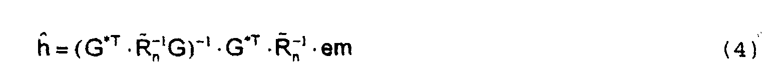
![]()
![]()
Zusammenhänge zwischen der Richtungsschätzung bzw. der Bestimmung der richtungsselektiven Kanalimpulsantworten und der Datendetektion werden wie folgt ausgenutzt. Die K Teilnehmersignale bestehen aus datentragenden Abschnitten und Trainingssequenzen, wobei aus den von den Trainingssequenzen der K Teilnehmersignale herrührenden Empfangssignalen die richtungsselektiven Kanalimpulsantworten bestimmt werden und die Daten aus den von den datentragenden Abschnitten herrührenden Empfangssignalen detektiert werden.Relationships between the directional estimate or the determination the directionally selective channel impulse responses and the Data detection is used as follows. The K subscriber signals consist of data-carrying sections and training sequences, from the training sequences of the K subscriber signals originating reception signals the directionally selective Channel impulse responses are determined and the Data from those originating from the data-bearing sections Receive signals are detected.
Auch können zur Aufwandsverringerung die Einfallsrichtungen DOA und/oder die richtungsselektiven Kanalimpulsantworten h mit einem Nachführverfahren nach eine Periode, die länger als eine funkblockbezogene Rahmenstruktur ist, erneut bestimmt werden.The directions of incidence can also be used to reduce expenditure DOA and / or the directionally selective channel impulse responses h with a follow-up procedure after a period longer than a frame structure related to the radio block is redetermined become.
FIG 4 zeigt einen richtungsselektiven Kanalschätzer JDCE, der Strahlformer BF enthält, die für die Ka Empfangssignale em(ka) jeweils eine Gewichtung durch strahlformerindividuelle Wichtungsfaktoren w1 bis w4 bzw. w5 bis w8 und ein Aufsummieren der Signalkomponenten in einer Summiereinrichtung S zu einem Signal, für das das Signal-Rausch-Verhältnis maximiert wird, vornehmen, wobei dieses Signal anschließend einem dekorrelierenden signalangepaßten Filter DMF zugeführt wird. In einer Einrichtung IC zur Interferenzauslöschung werden die Eigen- SI und Kreuzinterferenzen CI ausgeglichen und richtungsselektive Kanalimpulsantworten h gewonnen.4 shows a directionally selective channel estimator JDCE, which contains beamformers BF, each of which is weighted for the Ka receive signals em (ka) by weighting factors w1 to w4 or w5 to w8, which are individual to the beamformer, and a summation of the signal components in a summing device S to form a signal, for the signal-to-noise ratio is maximized, which signal is then fed to a decorrelating signal-matched filter DMF. In a device IC for interference cancellation, the intrinsic SI and cross interferences CI are compensated and directionally selective channel impulse responses h are obtained.
In den Strahlformern BF werden zusätzlich die Informationen über die Einfallsrichtungen DOA der Teilwellen und die Richtungen und relativen Leistungen der störenden Teilwellen verarbeitet. Diese Richtungen beeinflussen die Wichtungsfaktoren w1 bis w4 bzw. w5 bis w8 für jeden Strahlformer BF individuell. Die Strahlformer BF und die dekorrelierenden signalangepaßten Filter DMF wirken wie ein räumlich auflösendes dekorrelierendes signalangepaßtes Filter, die jeweils auf eine Teilwelle - somit K*Kd - angewandt werden.The information is also shown in the beam formers BF about the directions of incidence DOA of the partial waves and the directions and relative powers of the disturbing partial waves processed. These directions influence the weighting factors w1 to w4 or w5 to w8 for each beamformer BF individually. The BF beamformers and the decorrelating ones matched filter DMF act like a spatially resolving decorrelating signal-adapted filter, the each applied to a partial wave - thus K * Kd.
In FIG 5 wird die Detektionseinrichtung JDD gezeigt. Diese Detektionseinrichtung JDD verarbeitet die datentragenden Abschnitte der Empfangssignale e, wobei entsprechend der geschilderten Vorgehensweise beim richtungsselektiven Kanalschätzer JDCE ein räumlich auflösendes dekorrelierendes signalangepaßtes Filter die K*Kd Teilwellen der Empfangssignale e zum Maximieren des Signal-Rausch-Verhältnisses überlagert. Diese Maximierung des Signal-Rausch-Verhältnisses wird für jede Einfallsrichtung DOA eines jeden Teilnehmersignals durchgeführt, wobei die Kd Signalkomponenten der einzelnen Teilwellen eines Teilnehmersignals nach dem Maximum-Ratio-Combining-Verfahren in Summiereinrichtungen Sl bis SK überlagert werden.5 shows the detection device JDD. This Detection device JDD processes the data carriers Sections of the received signals e, corresponding to the described procedure for the directionally selective channel estimator JDCE is a spatially dissolving decoration matched filter the K * Kd partial waves of the received signals e to maximize the signal-to-noise ratio superimposed. This maximizing the signal-to-noise ratio is DOA of each subscriber signal for each direction of incidence performed, the Kd signal components of each Partial waves of a subscriber signal using the maximum ratio combining method in summing devices Sl to SK be overlaid.
Die Teilnehmersignale werden anschließend einer Einrichtung IC zur Interferenzauslöschung zugeführt, die die Intersymbol-ISI und Mehrfachzugriff- (Multiple Access) Interferenzen MAI ausgleicht. Dabei werden auch die Informationen über die Teilnehmerkodes c, die Einfallsrichtungen DOA, die richtungsselektiven Kanalimpulsantworten h und ggf. a-priori-Wissen über die Störer in Form von Rn verarbeitet. An einem Ausgang der Einrichtung IC zur Interferenzauslöschung liegen die detektierten Daten d der Teilnehmersignale separiert vor. Bei der Interferenzauslöschung kommt ein sogenanntes JD (Joint Detection) Verfahren zum Einsatz.The subscriber signals are then fed to a device IC for interference cancellation, which compensates for the intersymbol ISI and multiple access (MAI) interferences. The information about the subscriber codes c, the directions of incidence DOA, the directionally selective channel impulse responses h and possibly prior knowledge about the interferers are also processed in the form of R n . The detected data d of the subscriber signals are present separately at an output of the device IC for interference cancellation. A so-called JD (Joint Detection) procedure is used for interference cancellation.
Durch die erfindungsgemäße Empfangseinrichtung wird die zeitliche Dispersion und Varianz der Empfangssignale verringert. Weiterhin können durch die räumliche Auflösung eine größere Anzahl von Mobilstationen MS in einem Funkbereich einer Basisstation BS versorgt werden bzw. der Funkbereich kann durch die Richtwirkung derart gestaltet werden, daß auch die Sendeleistungen der Mobilstationen MS deutlich verringert werden.The temporal Dispersion and variance of the received signals reduced. Furthermore, the spatial resolution allows a larger one Number of mobile stations MS in a radio area Base station BS can be supplied or the radio area can be designed by the directivity in such a way that the Transmission power of the mobile stations MS significantly reduced become.
Claims (10)
- Method for channel assessment from received signals transmitted via a radio channel, in the case of which methodreceiving sensors of the receiving device receive Ka received signals which are composed of at least one subscriber signal marked by a transmitter-specific fine structure, a kth transmitter signal, k=1..K, being transmitted by Kd component waves differing in their direction of arrival (DOA) at the reception location,at least one direction of arrival (DOA) of a component wave of a subscriber signal being available in the receiving device, anddirectionally selective channel pulse responses (h) are determined from the Ka received signals and the direction of arrival (DOA).
- Method according to Claim 1, in which the directionally selective channel pulse responses (h) are determined from training sequences (tseq1, tseq2, ... tseqK), forming the transmitter-specific fine structures, of the subscriber signals.
- Method according to Claim 1 or 2, in which subscriber signals from a plurality of transmitters (MS) or reflectors (P1, P2) arrive in a fashion superimposed on the received signals at the receiving device, these signals being transmitted simultaneously in one frequency channel.
- Method according to one of the preceding claims, in which the directions of arrival (DOA) of the component waves and/or of interfering signals are present as a-priori knowledge in the receiving device.
- Method according to one of the Claims 1 to 3, in which the directions of arrival (DOA) of the component waves and/or interfering signals are determined from the received signals.
- Method according to Claim 5, in which additional information about at least one direction of arrival (DOA) and/or a correlation matrix of interfering signals are/is taken into account for determining the directions of arrival (DOA) of the component wave.
- Method according to Claim 5, in which non-directionally selective channel pulse responses (g) are determined from the received signals, and the direction of arrival (DOA) of at least one component wave is determined from the not directionally selective channel pulse responses (g).
- Method according to one of the preceding claims, in which the subscriber signals can be separated by individual training sequences (tseq1, tseq2, ... tseqK) in order to assign the directionally selective channel pulse responses (h) to transmitters (MS) or reflectors (P1, P2).
- Method according to one of the preceding claims, in which the subscriber signals can be separated by despreading with individual subscriber codes (tc1, tc2, .. tcK) in order to assign the directionally selective channel pulse responses (h) to transmitters (MS).
- Method according to one of Claims 4 or 5, in which averaging of the specific values is performed over a time interval in order to determine the directions of arrival (DOA) of the component waves.
Applications Claiming Priority (3)
| Application Number | Priority Date | Filing Date | Title |
|---|---|---|---|
| DE19712501 | 1997-03-25 | ||
| DE19712501 | 1997-03-25 | ||
| PCT/DE1998/000877 WO1998043459A2 (en) | 1997-03-25 | 1998-03-25 | Method for channel evaluation using receive signals transmitted via a radio channel |
Publications (2)
| Publication Number | Publication Date |
|---|---|
| EP1013003A2 EP1013003A2 (en) | 2000-06-28 |
| EP1013003B1 true EP1013003B1 (en) | 2003-05-14 |
Family
ID=7824564
Family Applications (1)
| Application Number | Title | Priority Date | Filing Date |
|---|---|---|---|
| EP98928071A Expired - Lifetime EP1013003B1 (en) | 1997-03-25 | 1998-03-25 | Method for channel evaluation using receive signals transmitted via a radio channel |
Country Status (7)
| Country | Link |
|---|---|
| US (1) | US6519477B1 (en) |
| EP (1) | EP1013003B1 (en) |
| JP (1) | JP3935969B2 (en) |
| CN (1) | CN1113485C (en) |
| DE (1) | DE59808380D1 (en) |
| ES (1) | ES2200348T3 (en) |
| WO (1) | WO1998043459A2 (en) |
Families Citing this family (17)
| Publication number | Priority date | Publication date | Assignee | Title |
|---|---|---|---|---|
| DE19825536B4 (en) * | 1998-06-08 | 2005-05-19 | IQ wireless GmbH, Entwicklungsgesellschaft für Systeme und Technologien der Telekommunikation | Method and apparatus for a full-duplex radio transmission system with CDMA access |
| FI982857A7 (en) * | 1998-12-31 | 2000-07-01 | Nokia Corp | Reception method and receiver |
| US6816541B1 (en) * | 1999-05-24 | 2004-11-09 | Texas Instruments Incorporated | Spread spectrum interference cancellation |
| CN1108071C (en) | 2000-04-11 | 2003-05-07 | 信息产业部电信科学技术研究院 | Signal processing method for terminal in CDMA mobile communication system |
| US6775261B1 (en) * | 2000-06-05 | 2004-08-10 | Lsi Logic Corporation | Frequency division multiple access system searching |
| US7720472B1 (en) * | 2000-09-14 | 2010-05-18 | The Directv Group, Inc. | Stratospheric-based communication system having interference cancellation |
| US6907270B1 (en) | 2000-10-23 | 2005-06-14 | Qualcomm Inc. | Method and apparatus for reduced rank channel estimation in a communications system |
| US8396513B2 (en) * | 2001-01-19 | 2013-03-12 | The Directv Group, Inc. | Communication system for mobile users using adaptive antenna |
| US7809403B2 (en) | 2001-01-19 | 2010-10-05 | The Directv Group, Inc. | Stratospheric platforms communication system using adaptive antennas |
| US7187949B2 (en) * | 2001-01-19 | 2007-03-06 | The Directv Group, Inc. | Multiple basestation communication system having adaptive antennas |
| US7558350B2 (en) * | 2003-03-04 | 2009-07-07 | Nec Corporation | Adaptive antenna reception device having excellent initial directional beam reception quality |
| US7313168B2 (en) | 2003-03-06 | 2007-12-25 | Nokia Corporation | Method and apparatus for receiving a CDMA signal |
| US7333575B2 (en) * | 2003-03-06 | 2008-02-19 | Nokia Corporation | Method and apparatus for receiving a CDMA signal |
| CN100431386C (en) * | 2005-05-12 | 2008-11-05 | 上海原动力通信科技有限公司 | Method for Estimating Direction of Arrival of Terminals in Multiple Cells on the Same Frequency |
| WO2008103089A1 (en) * | 2007-02-22 | 2008-08-28 | Telefonaktiebolaget Lm Ericsson (Publ) | A method and a device for reduced interference in a cellular access system |
| US10177947B2 (en) | 2015-07-24 | 2019-01-08 | Brian G. Agee | Interference-excising diversity receiver adaptation using frame synchronous signal features and attributes |
| US11381281B2 (en) * | 2020-02-04 | 2022-07-05 | Powermat Technologies Ltd. | Fast data transmission for wireless power transfer systems |
Family Cites Families (11)
| Publication number | Priority date | Publication date | Assignee | Title |
|---|---|---|---|---|
| US5299148A (en) * | 1988-10-28 | 1994-03-29 | The Regents Of The University Of California | Self-coherence restoring signal extraction and estimation of signal direction of arrival |
| US5255210A (en) * | 1988-10-28 | 1993-10-19 | The Regents Of The University Of California | Self-coherence restoring signal extraction apparatus and method |
| DE4201439A1 (en) * | 1992-01-21 | 1993-07-22 | Daimler Benz Ag | High-rate data transmission procedure via digital radio channel - providing multipath propagation compensation by decision feedback equaliser of correctly phased and weighted antenna signal combination |
| TW351886B (en) * | 1993-09-27 | 1999-02-01 | Ericsson Telefon Ab L M | Using two classes of channels with different capacity |
| JP3022194B2 (en) * | 1994-09-02 | 2000-03-15 | 三菱電機株式会社 | Diversity receiver |
| DE19511752A1 (en) | 1995-03-30 | 1996-10-10 | Siemens Ag | Process for high-resolution evaluation of signals for one- or two-dimensional direction or frequency estimation |
| DE19535441A1 (en) * | 1995-09-23 | 1997-03-27 | Bosch Gmbh Robert | Antenna of a central station of a point-to-multipoint radio relay system |
| US5887262A (en) * | 1996-04-19 | 1999-03-23 | Nokia Mobile Phones Limited | Smart antenna backwards compatibility in digital cellular systems |
| US5856804A (en) * | 1996-10-30 | 1999-01-05 | Motorola, Inc. | Method and intelligent digital beam forming system with improved signal quality communications |
| FI105063B (en) * | 1997-05-16 | 2000-05-31 | Nokia Networks Oy | Procedure for determining the direction of transmission and radio system |
| FI980616L (en) * | 1997-11-05 | 1999-05-06 | Nokia Telecommunications Oy | Method for improving radio connection quality in a cellular radio network |
-
1998
- 1998-03-25 WO PCT/DE1998/000877 patent/WO1998043459A2/en not_active Ceased
- 1998-03-25 JP JP54469798A patent/JP3935969B2/en not_active Expired - Fee Related
- 1998-03-25 ES ES98928071T patent/ES2200348T3/en not_active Expired - Lifetime
- 1998-03-25 EP EP98928071A patent/EP1013003B1/en not_active Expired - Lifetime
- 1998-03-25 DE DE59808380T patent/DE59808380D1/en not_active Expired - Lifetime
- 1998-03-25 CN CN98803717A patent/CN1113485C/en not_active Expired - Fee Related
-
1999
- 1999-09-27 US US09/407,257 patent/US6519477B1/en not_active Expired - Lifetime
Also Published As
| Publication number | Publication date |
|---|---|
| DE59808380D1 (en) | 2003-06-18 |
| WO1998043459A2 (en) | 1998-10-01 |
| EP1013003A2 (en) | 2000-06-28 |
| US6519477B1 (en) | 2003-02-11 |
| JP3935969B2 (en) | 2007-06-27 |
| ES2200348T3 (en) | 2004-03-01 |
| CN1251704A (en) | 2000-04-26 |
| CN1113485C (en) | 2003-07-02 |
| WO1998043459A3 (en) | 1999-01-21 |
| JP2001518261A (en) | 2001-10-09 |
Similar Documents
| Publication | Publication Date | Title |
|---|---|---|
| EP1013003B1 (en) | Method for channel evaluation using receive signals transmitted via a radio channel | |
| DE69521050T2 (en) | METHOD AND DEVICE FOR INTERFERENCE SUPPRESSION IN A DIGITAL CELLULAR MULTIPLE-ANTENNA COMMUNICATION SYSTEM | |
| DE69604595T2 (en) | METHOD AND ARRANGEMENT FOR SPATIAL MULTIPLEXING / DEMULTIPLEXING OF RADIO SIGNALS IN AN SDMA MOBILE RADIO SYSTEM | |
| DE69434616T2 (en) | Multipath reception using matrix calculations and adaptive beamforming | |
| DE69329893T2 (en) | Method and device for compensating for multipath fading and single-wave interference in a radio signal | |
| DE69924176T2 (en) | Common maximum likelihood follower with dynamic channel description | |
| DE69630616T2 (en) | ANGLE DIVERSITY METHOD AND BASE STATION DEVICE | |
| DE60110039T2 (en) | LINEAR SIGNAL SEPARATION THROUGH POLARIZATION DIVERSITY | |
| EP1166393B1 (en) | Beamforming method and device | |
| DE69606433T2 (en) | METHOD AND ARRANGEMENT FOR EQUALIZING MULTIPLE ANTENNA SIGNALS FOR MULTIPLE ELEMENT RECEPTION IN THE PRESENCE OF INTERFERENCE AND MULTIPLEWAY SPREADS | |
| DE69803454T2 (en) | RADIO BEARING METHOD AND INTERACTING TRANSMISSION DEVICE | |
| DE69936682T2 (en) | Base station and radio transmission method with receiver diversity | |
| DE69526603T2 (en) | Multi-user interference suppression for cellular mobile radio systems | |
| DE102011004257B4 (en) | Device and method for antenna diversity reception | |
| EP0970388B1 (en) | Method for evaluating direction | |
| EP0866568B1 (en) | Method and reception device for the detection of data | |
| EP0800285A2 (en) | Method for adjusting the parameters of a receiving apparatus, as well as corresponding receiving apparatus and radio station | |
| DE102011004259A1 (en) | Device and method for antenna diversity reception | |
| DE19604772C2 (en) | Method for parameterizing a receiving device, and corresponding receiving device and radio station | |
| DE10350362B4 (en) | Method for predicting a channel coefficient | |
| EP1004172B1 (en) | Channel estimation method and device | |
| DE4212300C2 (en) | Method and device for the simultaneous estimation of channels in digital message transmission in multiple access systems | |
| EP0900484B1 (en) | Process and device for the increase of subscriber capacity in a cellular mobile radio network | |
| DE69807522T2 (en) | DEVICE AND METHOD FOR DETERMINING THE SIGNAL DIRECTION FROM AN ESTIMATED SIGNAL MEDIUM RESPONSE FOR A RADIATION COMPONENT OF A RADIO SIGNAL | |
| DE19858951C2 (en) | Method and arrangement for generating predetermined directional characteristics |
Legal Events
| Date | Code | Title | Description |
|---|---|---|---|
| PUAI | Public reference made under article 153(3) epc to a published international application that has entered the european phase |
Free format text: ORIGINAL CODE: 0009012 |
|
| 17P | Request for examination filed |
Effective date: 19990917 |
|
| AK | Designated contracting states |
Kind code of ref document: A2 Designated state(s): DE ES FI IT NL |
|
| GRAH | Despatch of communication of intention to grant a patent |
Free format text: ORIGINAL CODE: EPIDOS IGRA |
|
| GRAH | Despatch of communication of intention to grant a patent |
Free format text: ORIGINAL CODE: EPIDOS IGRA |
|
| GRAA | (expected) grant |
Free format text: ORIGINAL CODE: 0009210 |
|
| AK | Designated contracting states |
Designated state(s): DE ES FI IT NL |
|
| REF | Corresponds to: |
Ref document number: 59808380 Country of ref document: DE Date of ref document: 20030618 Kind code of ref document: P |
|
| REG | Reference to a national code |
Ref country code: ES Ref legal event code: FG2A Ref document number: 2200348 Country of ref document: ES Kind code of ref document: T3 |
|
| PLBE | No opposition filed within time limit |
Free format text: ORIGINAL CODE: 0009261 |
|
| STAA | Information on the status of an ep patent application or granted ep patent |
Free format text: STATUS: NO OPPOSITION FILED WITHIN TIME LIMIT |
|
| 26N | No opposition filed |
Effective date: 20040217 |
|
| NLS | Nl: assignments of ep-patents |
Owner name: NOKIA SIEMENS NETWORKS GMBH & CO. KG Effective date: 20080115 |
|
| PGFP | Annual fee paid to national office [announced via postgrant information from national office to epo] |
Ref country code: ES Payment date: 20090324 Year of fee payment: 12 |
|
| PGFP | Annual fee paid to national office [announced via postgrant information from national office to epo] |
Ref country code: NL Payment date: 20090317 Year of fee payment: 12 Ref country code: FI Payment date: 20090313 Year of fee payment: 12 |
|
| REG | Reference to a national code |
Ref country code: NL Ref legal event code: V1 Effective date: 20101001 |
|
| PG25 | Lapsed in a contracting state [announced via postgrant information from national office to epo] |
Ref country code: FI Free format text: LAPSE BECAUSE OF NON-PAYMENT OF DUE FEES Effective date: 20100325 |
|
| PG25 | Lapsed in a contracting state [announced via postgrant information from national office to epo] |
Ref country code: NL Free format text: LAPSE BECAUSE OF NON-PAYMENT OF DUE FEES Effective date: 20101001 |
|
| REG | Reference to a national code |
Ref country code: ES Ref legal event code: FD2A Effective date: 20111118 |
|
| PG25 | Lapsed in a contracting state [announced via postgrant information from national office to epo] |
Ref country code: ES Free format text: LAPSE BECAUSE OF NON-PAYMENT OF DUE FEES Effective date: 20100326 |
|
| REG | Reference to a national code |
Ref country code: DE Ref legal event code: R081 Ref document number: 59808380 Country of ref document: DE Owner name: NOKIA SOLUTIONS AND NETWORKS GMBH & CO. KG, DE Free format text: FORMER OWNER: NOKIA SIEMENS NETWORKS GMBH & CO. KG, 81541 MUENCHEN, DE Effective date: 20140731 |
|
| PGFP | Annual fee paid to national office [announced via postgrant information from national office to epo] |
Ref country code: DE Payment date: 20150320 Year of fee payment: 18 |
|
| PGFP | Annual fee paid to national office [announced via postgrant information from national office to epo] |
Ref country code: IT Payment date: 20150330 Year of fee payment: 18 |
|
| REG | Reference to a national code |
Ref country code: DE Ref legal event code: R119 Ref document number: 59808380 Country of ref document: DE |
|
| PG25 | Lapsed in a contracting state [announced via postgrant information from national office to epo] |
Ref country code: DE Free format text: LAPSE BECAUSE OF NON-PAYMENT OF DUE FEES Effective date: 20161001 |
|
| PG25 | Lapsed in a contracting state [announced via postgrant information from national office to epo] |
Ref country code: IT Free format text: LAPSE BECAUSE OF NON-PAYMENT OF DUE FEES Effective date: 20160325 |