EP1012668B1 - Dye transfer apparatus and method for processing color motion picture film - Google Patents
Dye transfer apparatus and method for processing color motion picture film Download PDFInfo
- Publication number
- EP1012668B1 EP1012668B1 EP98948104A EP98948104A EP1012668B1 EP 1012668 B1 EP1012668 B1 EP 1012668B1 EP 98948104 A EP98948104 A EP 98948104A EP 98948104 A EP98948104 A EP 98948104A EP 1012668 B1 EP1012668 B1 EP 1012668B1
- Authority
- EP
- European Patent Office
- Prior art keywords
- film
- sandwich
- rollers
- matrix
- path
- Prior art date
- Legal status (The legal status is an assumption and is not a legal conclusion. Google has not performed a legal analysis and makes no representation as to the accuracy of the status listed.)
- Expired - Lifetime
Links
- 238000012546 transfer Methods 0.000 title claims abstract description 147
- 238000000034 method Methods 0.000 title claims abstract description 27
- 238000012545 processing Methods 0.000 title claims description 8
- 239000011159 matrix material Substances 0.000 claims abstract description 81
- 230000007246 mechanism Effects 0.000 claims description 17
- XLYOFNOQVPJJNP-UHFFFAOYSA-N water Substances O XLYOFNOQVPJJNP-UHFFFAOYSA-N 0.000 claims description 16
- 230000001360 synchronised effect Effects 0.000 claims description 4
- 238000010438 heat treatment Methods 0.000 claims 1
- 235000019589 hardness Nutrition 0.000 description 8
- 230000001276 controlling effect Effects 0.000 description 5
- 238000009826 distribution Methods 0.000 description 5
- 239000000463 material Substances 0.000 description 5
- 230000008569 process Effects 0.000 description 5
- 238000004519 manufacturing process Methods 0.000 description 4
- 239000007921 spray Substances 0.000 description 4
- 230000002411 adverse Effects 0.000 description 3
- 230000008859 change Effects 0.000 description 3
- 239000010935 stainless steel Substances 0.000 description 3
- 229910001220 stainless steel Inorganic materials 0.000 description 3
- 238000004891 communication Methods 0.000 description 2
- 238000010276 construction Methods 0.000 description 2
- 230000001965 increasing effect Effects 0.000 description 2
- 238000012423 maintenance Methods 0.000 description 2
- 230000002093 peripheral effect Effects 0.000 description 2
- 229920006267 polyester film Polymers 0.000 description 2
- 238000002360 preparation method Methods 0.000 description 2
- 230000001737 promoting effect Effects 0.000 description 2
- 230000004044 response Effects 0.000 description 2
- 238000005507 spraying Methods 0.000 description 2
- QTBSBXVTEAMEQO-UHFFFAOYSA-M Acetate Chemical compound CC([O-])=O QTBSBXVTEAMEQO-UHFFFAOYSA-M 0.000 description 1
- 229910001316 Ag alloy Inorganic materials 0.000 description 1
- 235000001674 Agaricus brunnescens Nutrition 0.000 description 1
- 229910001369 Brass Inorganic materials 0.000 description 1
- OYPRJOBELJOOCE-UHFFFAOYSA-N Calcium Chemical compound [Ca] OYPRJOBELJOOCE-UHFFFAOYSA-N 0.000 description 1
- 108010010803 Gelatin Proteins 0.000 description 1
- 229910002651 NO3 Inorganic materials 0.000 description 1
- NHNBFGGVMKEFGY-UHFFFAOYSA-N Nitrate Chemical compound [O-][N+]([O-])=O NHNBFGGVMKEFGY-UHFFFAOYSA-N 0.000 description 1
- BQCADISMDOOEFD-UHFFFAOYSA-N Silver Chemical compound [Ag] BQCADISMDOOEFD-UHFFFAOYSA-N 0.000 description 1
- 230000002745 absorbent Effects 0.000 description 1
- 239000002250 absorbent Substances 0.000 description 1
- 239000000654 additive Substances 0.000 description 1
- 239000010951 brass Substances 0.000 description 1
- 229910052791 calcium Inorganic materials 0.000 description 1
- 239000011575 calcium Substances 0.000 description 1
- 238000011161 development Methods 0.000 description 1
- 230000002708 enhancing effect Effects 0.000 description 1
- 229920000159 gelatin Polymers 0.000 description 1
- 239000008273 gelatin Substances 0.000 description 1
- 235000019322 gelatine Nutrition 0.000 description 1
- 235000011852 gelatine desserts Nutrition 0.000 description 1
- 238000005213 imbibition Methods 0.000 description 1
- 238000005259 measurement Methods 0.000 description 1
- 230000001105 regulatory effect Effects 0.000 description 1
- 230000008439 repair process Effects 0.000 description 1
- 238000000926 separation method Methods 0.000 description 1
- 229910052709 silver Inorganic materials 0.000 description 1
- 239000004332 silver Substances 0.000 description 1
- 238000002791 soaking Methods 0.000 description 1
- 239000000126 substance Substances 0.000 description 1
- 238000010023 transfer printing Methods 0.000 description 1
Images




Classifications
-
- B—PERFORMING OPERATIONS; TRANSPORTING
- B41—PRINTING; LINING MACHINES; TYPEWRITERS; STAMPS
- B41M—PRINTING, DUPLICATING, MARKING, OR COPYING PROCESSES; COLOUR PRINTING
- B41M5/00—Duplicating or marking methods; Sheet materials for use therein
- B41M5/26—Thermography ; Marking by high energetic means, e.g. laser otherwise than by burning, and characterised by the material used
- B41M5/382—Contact thermal transfer or sublimation processes
- B41M5/38207—Contact thermal transfer or sublimation processes characterised by aspects not provided for in groups B41M5/385 - B41M5/395
- B41M5/38221—Apparatus features
-
- G—PHYSICS
- G03—PHOTOGRAPHY; CINEMATOGRAPHY; ANALOGOUS TECHNIQUES USING WAVES OTHER THAN OPTICAL WAVES; ELECTROGRAPHY; HOLOGRAPHY
- G03B—APPARATUS OR ARRANGEMENTS FOR TAKING PHOTOGRAPHS OR FOR PROJECTING OR VIEWING THEM; APPARATUS OR ARRANGEMENTS EMPLOYING ANALOGOUS TECHNIQUES USING WAVES OTHER THAN OPTICAL WAVES; ACCESSORIES THEREFOR
- G03B27/00—Photographic printing apparatus
- G03B27/02—Exposure apparatus for contact printing
- G03B27/04—Copying apparatus without a relative movement between the original and the light source during exposure, e.g. printing frame or printing box
- G03B27/08—Copying apparatus without a relative movement between the original and the light source during exposure, e.g. printing frame or printing box for automatic copying of several originals one after the other, e.g. for copying cinematograph film
-
- G—PHYSICS
- G03—PHOTOGRAPHY; CINEMATOGRAPHY; ANALOGOUS TECHNIQUES USING WAVES OTHER THAN OPTICAL WAVES; ELECTROGRAPHY; HOLOGRAPHY
- G03C—PHOTOSENSITIVE MATERIALS FOR PHOTOGRAPHIC PURPOSES; PHOTOGRAPHIC PROCESSES, e.g. CINE, X-RAY, COLOUR, STEREO-PHOTOGRAPHIC PROCESSES; AUXILIARY PROCESSES IN PHOTOGRAPHY
- G03C7/00—Multicolour photographic processes or agents therefor; Regeneration of such processing agents; Photosensitive materials for multicolour processes
- G03C7/22—Subtractive cinematographic processes; Materials therefor; Preparing or processing such materials
- G03C7/25—Dye-imbibition processes; Materials therefor; Preparing or processing such materials
Definitions
- the present invention relates generally to film processing, and more particularly to an improved system and method for producing printed copies of motion picture films by dye transfer.
- matrix and receiver films were placed in intimate contact with each other via a multi-stage seating mechanism generally known as a roll tank. While being placed into intimate contact with each other, the two films were also seated onto a stainless steel ribbon, known as a pin belt
- the pin belt typically traveled in an orbital path extending around and between two or more drums or wheels.
- the perforations or sprocket holes of the sandwiched films were placed over silver alloy pins raised above the flat stainless steel ribbon. Both films remained firmly seated on the pin belt for the duration of time needed for complete dye transfer from matrix to receiver, generally about thirty five seconds.
- U.S. Patent No. 2,457,319 discloses a conventional pin belt dye transfer apparatus.
- U.S. Patent No. 3,750,567 discloses a dye transfer apparatus including rotatable plate cylinders upon which matrix films are wound, and a series of rollers for successively contacting the matrix films with a receiver film to complete dye transfer.
- Photographic film processing does not provide the precise color control of tone scale and color reproduction available using dye transfer processing, which may result in inferior color rendition in photographic film prints. Further, photographic film has a greater tendency to fade over time, resulting in a less durable print.
- the present invention is directed to a system for producing printed copies of films by dye transfer. More particularly, the present invention is directed to an apparatus and method for maintaining sandwiched films, comprising a matrix film superimposed onto a receiver film, in precise registration during dye transfer, the predominance of which is accomplished without a pin belt.
- a dye transfer apparatus in accordance with the present invention includes a roll tank having a first plurality of rollers in a predetermined orientation.
- the first plurality of rollers is adapted to superimpose a blank or receiver film onto a dye-imbibed matrix film in a predetermined registration, i.e. to place the receiver and matrix films in intimate contact, thereby creating a two-film "sandwich" for dye transfer.
- the roll tank communicates with a pin belt, which includes a plurality of pins or teeth on a ribbon traveling in an orbital path.
- the pins engage sprocket holes in the two-film sandwich delivered within the roll tank, thereby directing the two-film sandwich along a portion of the orbital path.
- the pins also have a predetermined spacing therebetween for maintaining the two-film sandwich in precise registration as they travel along the orbital path.
- a first stripping roller is provided in communication with the pin belt, which strips the two-film sandwich from the pin belt, while maintaining the films in precise registration and without adversely affecting the adhesion between the films,
- a transfer cabinet then receives the two-film sandwich from the first stripping roller to complete dye transfer.
- the transfer cabinet includes a second plurality of rollers having a predetermined relationship to one another, and an elevator mechanism for adjusting the predetermined relationship.
- the rollers in the transfer cabinet have relatively large diameters compared to the other rollers in the apparatus, thereby defining substantially rectilinear paths along their perimeters.
- the rollers define a film path along which the two-film sandwich travels through the transfer cabinet, the two-film sandwich traveling systematically around a portion of the perimeters of the rollers and between the rollers in a predetermined sequence.
- the rollers also preferably have substantially uniform, toothless perimeters, thereby allowing the two-film sandwich to travel along the perimeters thereof without requiring sprockets or teeth to engage the two-film sandwich, while maintaining the films in precise registration and without adversely affecting the adhesion between the films.
- the elevator mechanism includes one or more servo-motors for precisely adjusting the position of one or more corresponding rollers within the transfer cabinet, thereby providing a predetermined tension on the two-film sandwich traveling along the film path.
- the elevator mechanism may be adjusted manually, or may include one or more sensors for measuring the actual tension of the two-film sandwich as it travels along the film path.
- the transfer cabinet also includes a pair of synchronized servo-motors for adjusting the distribution of tension of the two film sandwich, thereby providing additional tension adjustment, and thereby further maintaining the two-film sandwich in precise registration and without adversely affecting the adhesion between the films.
- the transfer cabinet also provides predetermined atmospheric conditions, such as a predetermined temperature and humidity, to promote complete dye transfer from the dye imbibed matrix to the receiver film as the two-film sandwich travels through the cabinet in a predetermined time.
- predetermined atmospheric conditions such as a predetermined temperature and humidity
- a second stripping roller including a third plurality of rollers in a predetermined orientation, is provided in communication with the film path of the transfer cabinet.
- the third plurality of rollers separate the matrix film from the receiver film after complete dye transfer has occurred within the transfer cabinet.
- the separated receiver film may then be processed using other apparatus and methods to provide a finished print.
- the receiver film may be directed through a subsequent system similar to that just described to transfer an additional color to the receiver film.
- the matrix film may be directed through dying equipment, or a spray dye tank, and followed by a washback system enclosure, in preparation for dye transfer to a subsequent receiver film.
- a dye transfer printing system in accordance with the present invention reduces the length of pin belt necessary for an individual dye transfer path, and allows the system to operate at higher speeds than traditional pin belt systems to produce film prints in greater volume in a commercially feasible manner.
- a roll tank in accordance with the present invention may include rollers having a predetermined hardness and which apply a predetermined pressure to the two-film sandwich to promote adhesion and/or dye transfer at substantially higher speeds than previous systems.
- a pin belt in accordance with the present invention may have an orbital path or peripheral length less than 73 meters (200 feet), and preferably 8 meters (22 feet).
- the pin belt includes specially designed and/or arranged pins adapted to facilitate seating and stripping of the films from the pin belt at relatively high speeds without risk of damaging the films.
- the pin belt may be operated at speeds of 292 meters per minute (800 feet per minute) or more, and preferably between 365 and 437 meters per minute (1,000 and 1,200 feet per minute), without risk of damaging and/or misaligning the two-film sandwich during seating and subsequent stripping. These parameters result in the two-film sandwich being on the pin belt for not more than about 1 or 2 seconds, that is, less than 10% of the about 45-50 seconds generally needed for complete dye transfer.
- a dye transfer apparatus in accordance with the present invention completes dye transfer without a pin registration device such as the pin belt, and preferably while the two-film sandwich is directed along a pinless substantially rectilinear path, such as within the transfer cabinet.
- the film path preferably has a length that is sufficiently long such that the two-film sandwich travel through the transfer cabinet in 45 seconds or more, preferably in 45-50 seconds, thereby allowing complete dye transfer to occur therein.
- the substantially rectilinear path defined by the relatively large diameter rollers and the natural adhesion of the films promoted by the tension adjustment provided by the elevator mechanism allow the transfer cabinet to maintain the two-film sandwich in precise registration without the need for pins or sprockets, thereby allowing the films to travel along the film path at higher speeds than previously available.
- a principal object of the present invention is to provide a dye transfer apparatus that reduces the length of pin belt needed to maintain a matrix film and a receiver film in precise registration during dye transfer.
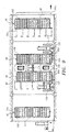
- FIG. 1 shows a schematic plan of a dye transfer system 10 in accordance with the present invention.
- the system 10 is used to print a copy of a professional motion picture using a three color dye transfer process.
- a blank or receiver film 12 is provided into which dye is transferred to create the copied print (called an imbibition dye transfer print or an "IB print"), and a matrix film 14 is provided to transfer a colored dye into the blank film 12.
- IB print imbibition dye transfer print
- a matrix film 14 is provided to transfer a colored dye into the blank film 12.
- the materials and construction of the films for example the polyester film base used, as well as their chemical properties, are known and will not be addressed herein.
- the system 10 includes a continuous path or loop for the matrix film 14 and a continuous path for the blank film 12.
- the matrix film path 14 includes equipment for applying dye to the matrix film, namely a dye tank 30, a washback system enclosure 32, and includes a dye transfer apparatus 40 for completing dye transfer to the blank film 12.
- the apparatus 40 includes a roll tank 42, a pin belt apparatus 44, a first stripping roller 46, a transfer path cabinet 48, and a second stripping roller 50.
- the roll tank 42 includes a wet section 52 and a dry section 54.
- Each section 52, 54 is preferably a enclosed separate chamber within the roll tank 42 connected by openings through which the blank film 12, the matrix film 14 and the pin belt 70 (all shown in phantom) may travel.
- the roll tank 42 also includes a plurality of rollers 56-64, preferably having smooth perimeters, rotatably fixed in a predetermined relationship within the roll tank 42.
- the wet section 52 includes a roller 56 which receives the dye imbibed matrix film 14 and guides it onto the pin belt 70, Roller 58 receives the blank film 14 and directs it towards a first pair of rollers 60.
- the first pair of rollers 60 cooperatively direct the blank film 12 onto the pin belt 70 and superimpose the blank film 12 onto the matrix film 14 in a predetermined registration to create a two-film sandwich 16 (not shown in FIG. 3),
- the pre-wet blank film 12 may be seated first on the pin belt 70, followed by the matrix film 14.
- the second pair of rollers 62 apply a predetermined pressure to further seat the films 12, 14.
- the wet section 52 preferably includes conditions that facilitate initial seating and adhesion of the films 12, 14. For example, water may be injected or sprayed between the films 12, 14 as they are being seated onto the pin belt 70. Alternatively, the wet section 52 may be filled with water into which the films 12, 14 may be totally immersed. The water allows the films 12, 14 to move into registration with one another, and the subsequent removal of that water under pressure removes entrained air and promotes the natural adhesion of the two-film sandwich 16, i.e., the tendency of wet films to adhere to one another, to help reduce misalignment and maintain the films 12, 14 in precise registration.
- water may be injected or sprayed between the films 12, 14 as they are being seated onto the pin belt 70.
- the wet section 52 may be filled with water into which the films 12, 14 may be totally immersed. The water allows the films 12, 14 to move into registration with one another, and the subsequent removal of that water under pressure removes entrained air and promotes the natural adhesion of the two-film sandwich 16,
- temperature-controlled water i.e. water that is heated to a predetermined temperature is injected between the films 12, 14 as they are being placed in intimate contact with one another.
- water at temperatures of between 38-43 degrees Celsius (100-110 degrees Fahrenheit), and preferebly 41 degrees Celsius (105 degrees Fahrenheit) may be appropriate for this purpose.
- one or more additives may be provided in the water to promote adhesion and/or facilitate dye transfer.
- the dry section 54 includes two pairs of rollers 64a, 64b which also apply a predetermined pressure to the two-film sandwich 16 and remove excess water from between the films 12, 14 for optimum dye transfer.
- the location of the rollers 56-64 within the roll tank 42 and in relation to each other may be manually and/or automatically adjustable to maintain the predetermined registration and the predetermined pressure.
- the relative positions of the pairs of rollers 60-64 are pneumatically controlled to apply the predetermined pressure to the two-film sandwich 16, typically between 82 kPa (12 psi) and 205 kPa (30 psi).
- the wet section rollers 60, 62 may apply pressures of between 123-171 kPa (18-25 psi) to the films 16, with 171 kPa (25 psi) presently being most preferred.
- the dry section rollers 64a, 64b may apply pressures of between 68-171 kPa (10-25 psi), with 171 kPa (25 psi) being preferred for the first pair of rollers 64a, and 103 kPa (15 psi) being preferred for the second pair of rollers 64b.
- the rollers 60-64 also preferably have predetermined hardnesses to enhance point-to-point contact and to drive out the excess water and entrained air to further promote optimum adhesion and/or dye transfer.
- the rollers 60-64 have a rigid inner run (e.g. rim 162 on roller 62), which may be furnished from brass or other conventional material, and an annular tire (e.g. tire 163 on roller 62) furnished from rubber or similar material having a predetermined hardness.
- a rigid inner run e.g. rim 162 on roller 62
- an annular tire e.g. tire 163 on roller 62
- hardnesses of between 65A and 85A have been found to be useful for the present invention.
- the upper rollers 60, 62, 64a and 64b have hardnesses of 75A, 65A, 85A and 75A respectively, while the lower rollers 60, 62, 64a, and 64b all preferably have a hardness of 75A.
- the predetermined hardnesses and pressures of the pairs of rollers 60-64 provide improved conditions for maintaining the films 12, 14 in precise registration during the high speeds of the present dye transfer system.
- the pin belt apparatus 44 which includes the pin belt 70 and a pair of wheels 74, 76 supported by a conventional frame structure 75,
- the pin belt 70 is an endless ribbon traveling in an orbital path 72 (shown in phantom) around and between the two wheels 74, 76.
- the pin belt 70 is preferably produced from stainless steel using known methods and constructions, and has a periphery defined by said orbital path 72, preferably less than about 73 meters (200 feet), and more preferably between 7 and 8 meters (18 and 22 feet) in length.
- the wheel 74 is adjustably mounted to the frame 75 and may freely rotate, while the wheel 76 is motor-driven, thereby allowing the pin belt to engage the wheels and travel along the orbital path 72.
- a weighted rack and pinion apparatus 78 allows the location of wheel 74 to be adjusted and locked, thereby regulating the distance between the wheels 74, 76 and applying a predetermined tension to the pin belt 70 proportional to the weight 79.
- the servo-motor 84 drives the wheel 76, thereby controlling the speed of the pin belt 70 and applying further desired tension to the two-film sandwich 16 traveling along the orbital path 72.
- the pin belt 70 includes a plurality of pins or teeth 71 permanently attached to or integrally formed on the outer surface of the pin belt 70, preferably being force fit through pre-punched openings spaced along the pin belt ribbon.
- the pins are spun from coin silver to a predetermined shape adapted to facilitate the pin belt 70 detachably receiving and engaging perforations or sprocket holes 13 in the two-film sandwich 16.
- the pins 71 also have a predetermined spacing therebetween for maintaining the two-film sandwich 16 in precise registration as they travel along the orbital path 72 (e.g. about 4.757 mm (0.187275 inches)).
- the pin belt 70 has a pairs of pins 71a, 71b spaced along the length of the pin belt 70, the pins within each pair being spaced apart across a width, e.g. 28.17 mm (1.109 inches), of the pin belt 70, thereby corresponding to the two sets of sprocket holes provided on conventional film strips.
- one set of pins 71a is "full-fitting," that is, has a shape and size similar to the corresponding holes 13 in the films 16, while the other set of pins 71b has a smaller size, e.g.
- FIGS. 11A-11C a portion of a preferred embodiment of a pin belt 70 (shown in phantom in FIG. 11A) is shown having a full-fitting pin 71a adjacent a smaller pin 71b.
- the pin 71a has a rectangular shape corresponding to the shape of the sprocket holes 13 of the two-film sandwich film 16, preferably having rounded edges.
- the pin 71a has a domed or mushroom cross-section for facilitating the seating and stripping of the films 16 on and from the pin belt 70 under high speed conditions.
- the smaller pin 71b also has a rectangular shape and a domed cross-section, although smaller in width and length than the full-fitting pin 71a.
- the pins 71a, 71b are fastened to the pin belt 70 such that the front surfaces 170a, 171a are parallel and adjacent to one another.
- the front surfaces 170a, 171a both engage the leading edge 113a of the sprocket holes 13 on the two-film sandwich 16 to maintain the films in precise registration as they are directed along the orbital path (not shown) in the direction indicated by arrow 180.
- the rear surface 170c of the full-fitting pin 71a engages the trailing edge 113c of the sprocket hole 13, while the rear surface 171c of the smaller pin 71b does not.
- the side surfaces 171b of the smaller pin 71b do not engage the side edges 113b of the sprocket 13.
- the full-fitting pin 71a may have a height 173 of 15.9 mm (0.625 inch), a width 170a of 2.79 mm (0.110 inch), and a length 170b of 1.98 mm (0.078 inch) (corresponding to the width and length of the sprocket hole 13).
- the smaller pin 71b may have a height 173 of 15.9 mm (0.625 inch), a width 171a of 2.54 mm (0.100 inch), and a length less than 1.85 mm (0.073 inch).
- the first stripping roller 46 Attached to the pin belt machine 44 is the first stripping roller 46 which generally includes one or more rollers for stripping or guiding the two-film sandwich 16 from the pin belt 70.
- the first stripping roller 46 includes a smooth perimeter roller 80 which facilitate removing the two-film sandwich 16 from the pins of the pin belt 70.
- the roll tank 42 and the first stripping roller 46 are generally attached to or integrally formed on the pin belt apparatus 44.
- the roll tank 42 is mounted on a central, upper portion of the pin belt apparatus 44, whereby the blank and matrix films 12, 14 are directed onto a flat segment of the pin belt 70.
- the first stripping roller 46 be mounted adjacent a flat segment of the pin belt 70 to facilitate removal of the two-film sandwich 16 therefrom.
- the two-film sandwich 16 preferably travels along only a portion of the orbital path 72 between the roll tank 42 and the first stripping roller 46.
- each component may be provided separately or may be mounted in alternative configurations to that shown without affecting the operation of the apparatus 40.
- the transfer cabinet 48 which includes an arrangement of elevator-controlled rollers 86-92 mounted within a enclosed cabinet 49.
- the cabinet 49 includes openings (not shown) into and out of the cabinet 49 to a continuous film path 94 along which the two-film sandwich 16 may be directed, for example, from the pin belt apparatus 44 into the transfer cabinet 48, and from the transfer cabinet 48 to the second stripping roller 50.
- the rollers 86-92 are rotatably mounted in a predetermined relationship to one another to provide the continuous film path 94 along which the two-film sandwich 16 may travel.
- the film path 94 defined by the rollers 86-92 should provide sufficient length and time for complete dye transfer to occur within the transfer cabinet 48.
- the rollers 86, 88, 92 are mounted in banks, sharing common axles 96, 98 and support frames 100. Rollers 90 are mounted independently in banks using support frames 102. In addition, the banks are slightly offset from one another, such that the arrangement of rollers 86-92 defines one or more helical paths defining the overall film path 94. Preferably, the arrangement of the rollers 86-92 defines a film path 94 having a length higher than 75 m (205 feet), preferably between 219 and 365 meters (600 and 1,000 feet), and most preferably between 273 and 328 meters (750 and 900 feet).
- the two-film sandwich 16 remains in the transfer cabinet 48 for between about 45-50 seconds, and preferably not more than 45 seconds, while traveling at drive speeds greater than 120 meters per minute (330 feet per minute), preferably between 292-437 meters per minute (800-1,200 feet per minute), and most preferably between 365-437 meters per minute (1,000-1,200 feet per minute), or more.
- the transfer cabinet 48 preferably includes two similar sets of rollers 86-92, in substantially opposite-hand arrangements 104, 106.
- the banks of rollers 86, 88, 92 have 18 rollers each mounted on common axles 96, 98 and frames 100, while banks of rollers 90 have 18 rollers mounted on frames 102.
- the film path 94 of the transfer cabinet 48 is defined by a series of substantially straight paths extending between the rollers 86-92 which begins at a point 94a where the two-film sandwich 16 enters the transfer cabinet 48.
- a first roller 86a diverts the film path 94 vertically along path 94b to a second roller 90.
- the film path 94 then follows the additional rollers 90, 92 along paths 94c, 94d, and 94e at which point, because of the offset of the banks, the path 94 loops helically back to roller 86b adjacent to roller 86a.
- the path 94 then extends helically along the banks of rollers 86, 90, and 92 until roller 90a. At that point, the path 94 extends along path 94f to roller 90b in the second arrangement 106.
- the film path 94 then follows paths 94g, 94h, and 94i helically through the second arrangement 106 of rollers 88-92, until roller 88a, whereupon path 94j leads out of the transfer cabinet 48.
- the rollers 86-92 preferably have diameters that are larger than the diameters of the rollers used elsewhere in the apparatus 40 and those used in previous dye transfer systems, for example larger than 100 mm (4 inches) and preferably between 229 mm and 456 mm (9 inches and 18 inches).
- the larger diameters result in the perimeters of the rollers 86-92 defining substantially rectilinear paths, that is, the perimeters are sufficiently large compared to the thickness of the two-film sandwich 16 that the rollers 86-92 behave similarly to a substantially straight path rather than a tightly curved path.
- the two-film sandwich 16 although traveling helically along the film path 94 through the arrangement of rollers 86-92, follows a substantially rectilinear path. Rollers having diameters of about 301 mm (11-7/8 inches) are presently most preferred for providing a desired substantially rectilinear path.
- the rollers 86-92 arc toothless and have substantially uniform perimeters, that is, they have no sprockets for engaging the holes in the two-film sandwich 16.
- the blank and matrix films 12, 14 may have a tendency to shift or slide in relation to one another, thereby compromising the registration needed for proper dye transfer.
- small diameter rollers usually have sprockets to engage the two-film sandwich 16 and maintain the films 12, 14 in precise registration.
- the films 12, 14 do not tend to slide in relation to one another because of the substantially rectilinear paths defined by the relatively large diameters of the rollers 86-92.
- the rollers 86-92 do not need sprockets, pins or teeth which may risk damaging the two-film sandwich 16.
- the transfer cabinet 48 generally also includes an elevator mechanism for adjusting the predetermined relationship of the rollers 86-92 to provide a desired or predetermined tension on the two-film sandwich 14 traveling along the film path 94.
- the elevator mechanism includes a tension drive motor 112 for controlling the vertical position of the rollers 90.
- the tension drive motor 112 has a roller chain 114 attached thereto which also communicates with a carriage or beam 116.
- the carriage 116 is a rigid frame assembly that is slidably attached to rails 118, thereby allowing the carriage 116 to be precisely adjusted vertically within the cabinet 49, as the motor 112 drives the chain 114 (e.g. between an upper position during operation and a lower position for service and maintenance, both of which are shown).
- the rollers 90 are mounted on frames 102 which are attached to the carriage 116 as shown, thus allowing the distance (represented by paths 94b, 94d, 94g, and 94i) between the upper rollers 90 and the lower rollers 86, 88, and 92 to be adjusted, and thereby adjusting the tension of the two-film sandwich 16 traveling along the film path 94.
- the carriage 116 is manually controlled, thereby allowing an operator to adjust the tension and/or to lower the carriage 116 for maintenance.
- one or more banks or individual rollers may be adjustable within the transfer cabinet 48 to provide suitable tension adjustment.
- the elevator mechanism may include one or more interacting sensors and servo-motors (not shown) which measure actual tension experienced by the two-film sandwich 16 traveling along the film path 94, and precisely move one or more rollers in relation to the others in response to the actual tension measurements.
- the sensors and servo-motors may be used to adjust the actual tension towards the predetermined tension, thereby further maintaining the films 12, 14 in precise registration.
- the transfer cabinet 48 includes a pair of synchronized drive motors 108, 110.
- the motors 108, 110 drive the axles 98 of the bank of rollers 86, 88, thereby controlling the distribution of tension of the two-film sandwich 16 traveling along the film path 94.
- the axles 98 and motors 108, 110 comprise a tangentially driven system, as will be familiar to those skilled in the art.
- the motor 108 draws the two-film sandwich 16 from the pin belt 70 into the transfer cabinet 48
- the motor 110 draws the two-film sandwich 16 through the film path 94.
- the speed of the motors 108, 110 may be adjusted relative to one another to provide further tension control of the two-film sandwich 16 traveling along the film path 94.
- the motor 112 applies a relatively high tension to the two-film sandwich 16 as it travels along the film path 94, as compared to when the two-film sandwich 16 travels along the orbital path 72 on the pin belt 70, thereby enhancing the films 12, 14 remaining in precise register within the transfer cabinet 48.
- the motor 112 may apply a tension of about 7-8 pounds to the two-film sandwich 16, while the two-film sandwich 16 may only be subjected to about 2-3 pounds of tension while on the pin belt 70.
- the transfer cabinet 48 is preferably maintained at predetermined atmospheric conditions for optimizing complete dye transfer in a predetermined time.
- the chamber within the transfer cabinet 48 may be heated to temperature of between 43 and 49 degrees Celsius (110 and 120 degrees Fahrenheit), preferably 44 degrees Celsius (112 degrees Fahrenheit), thereby providing conditions for complete dye transfer to occur in 45-50 seconds.
- the temperature within the transfer cabinet 48 may be reduced, possibly as low as ambient temperatures, but this may increase the time needed for complete dye transfer (i.e. the time that the two-film sandwich 16 must remain within the transfer cabinet 48), and consequently increase the required length of the film path 94. Increasing the temperature may shorten the transfer time, but may also risk damage to the films as they are separated from each other.
- the transfer cabinet 48 is also preferably maintained at a relative humidity of between 45% and 50%. Such humidity may facilitate transporting of the two-film sandwich 16 over the surface of the rollers, by reducing friction. Substantially lower humidity conditions, for example 10 percent or less may cause the films to curl or otherwise damage the films.
- the second stripping roller 50 which includes a plurality of rollers arranged in a predetermined orientation.
- cooperating sprocket 120 and roller 124 are adapted to "strip" or separate the two-film sandwich 16 into the blank film 12 (with the dye transferred thereon) and the matrix film 14.
- the roller 124 may be mounted on an adjustable keeper assembly 122, and the sprocket 120 may be driven by a servo-motor 132 to decouple the tension applied within the transfer cabinet 48 (e.g. to reduce the tension of the two-film sandwich 16 to about 2 pounds) and drive the matrix film 14.
- the roller 126 then directs the matrix film 14 out of the second stripping roller 50 and through the matrix film loop 14, as discussed below,
- the sprocket 128 and roller 130 direct the blank film 12 out of the second stripping roller 50 for subsequent processing, e.g. to the blank dry box 36 (see FIG. 1).
- the sprocket 128 has a motor 134 connected thereto to drive the blank film 12 after separation from the matrix film 14.
- a dye transfer apparatus in accordance with the present invention allows dye transfer to occur at higher drive speeds than previously available using traditional pin belt systems. For example, if a drive speed of 365-437 meters per minute (1,000-1,200 feet per minute) is desired and conditions arc such that the two-film sandwich must remain superimposed in precise register for 45 seconds, a path length of 273-328 meters (750-900 feet) is needed. Thus, a traditional pin belt apparatus operating at such speeds would have to be hundreds of feet long, requiring substantial space.
- a transfer cabinet in a dye transfer apparatus in accordance with the present invention may provide between 273-328 meters (750-900 feet) of film path length in only 6.6 square meters (50 square feet) (e.g. a transfer cabinet having a foot print of 3.6 meters (10 feet) by 1.8 meters (5 feet)).
- the matrix film 14 is provided in a continuous loop that is fed through a series of equipment, including a rinse tank 20, a matrix dry box 22, a first elevator mechanism 24, a matrix change station 26, a second elevator mechanism 28, a dye tank 30, and a washback tank 32, all of which are conventional.
- the matrix film 14 is then directed through a dye transfer apparatus in accordance with the present invention, such as the preferred embodiment described above.
- the rinse tank 20 sprays water onto the surface of the matrix film 12 to remove any residue remaining thereon from a previous dye transfer cycle.
- the matrix dry box 22 then dries the rinsed matrix film 14 as it passes therethrough, typically using forced hot air.
- the matrix film 14 passes through the matrix change station 26 which allows the matrix to be changed-out between cycles and replaced with a new matrix film 14, and/or provides continuity for the matrix film 14 traveling around the loop.
- Elevator mechanisms are provided, which include one or more motor-driven rollers or other driving mechanisms (not shown) for drawing the matrix film 14 through the loop, and a plurality of rollers (not shown) in an adjustable relationship to one another for controlling tension on the matrix film 14.
- a first elevator mechanism 24 draws the matrix film 14 from the dye transfer apparatus 40 through the rinse tank 20 and the matrix dry box 24.
- a second elevator mechanism 28 is also provided which draws the matrix film 14 from the matrix change station 26.
- the matrix film 14 then enters the dye tank 30 which includes a plurality of spray nozzles (not shown) for spraying a particular color dye into the surface of the matrix film 14, soaking the surface of the matrix film 14.
- the matrix film 14 then travels to the washback tank 32 which includes a plurality of nozzles (not shown) for spraying water onto the matrix film 14, thereby removing excess dye from the surface thereof to control the color ratio of the completed print.
- the washback tank 32 which includes a plurality of nozzles (not shown) for spraying water onto the matrix film 14, thereby removing excess dye from the surface thereof to control the color ratio of the completed print.
- the blank or receiver film 12 is directed along a continuous path, including a pre-wet tank 34, the dye transfer apparatus 40, and a blank dry box 36.
- the pre-wet tank 34 sprays water onto the blank film 12 to moisten a gelatin or other absorbent material on the surface thereof for receiving dye.
- the blank and matrix films 12, 14 are then directed into the roll tank 42, where they are superimposed together under a predetermined pressure in a predetermined registration to create the two-film sandwich 16.
- the films 12, 14 are directed onto the pin belt 70, which guides them partially around the orbital path 72 thereof.
- the first stripping roller 46 removes the two-film sandwich 16 from the pin belt 70 and directs it into the transfer cabinet 48.
- the two-film sandwich 16 is then directed along the film path 94 (not shown in FIG. 2) defined by the plurality of rollers 86-92 for sufficient time for dye transfer to be substantially completed.
- the film path 94 (not shown in FIG. 2) defined by the plurality of rollers 86-92 for sufficient time for dye transfer to be substantially completed.
- part of the dye transfer process may occur prior to the transfer cabinet 48, it is preferred that all or most of the process occur in the transfer cabinet, rather than on the pin belt 70.
- the pin belt 70 acts primarily as a seating device, allowing the films 12, 14 to be initially superimposed in precise register thereon.
- the two-film sandwich 16 may then be removed therefrom and directed into an apparatus, such as the transfer cabinet 48, where dye transfer occurs without using a registration device, such as pins, which engage the sprocket holes of the films 12, 14 to keep them in precise registration.
- the transfer cabinet 48 defines a chamber that provides substantially stable atmospheric conditions to promote dye transfer in a predetermined transfer time, for example, the predetermined temperatures and/or humidity discussed above.
- the precise register of the two-film sandwich 16 is enhanced throughout the orbital path 72 and the film path 94 traveled by promoting the adhesion and controlling the tension of the two-film sandwich 16.
- the pins on the pin belt 70 prevent the tensioned two-film sandwich 16 from misaligning during seating on the pin belt 70.
- the tension control of the elevator mechanism protects the adhesion between the two-film sandwich 16 to maintain the films 12, 14 in precise registration throughout the film path 94.
- the predetermined relationship of the rollers 86-92 may be manually and/or automatically adjusted in response to the actual tension experienced by the two-film sandwich 16, for example using the tension motor assembly 112-116, thereby maintaining the tension substantially at a predetermined tension that promotes the sandwiches films 16 remaining in precise registration.
- the drive speeds of the synchronized motors 108, 110 may also be adjusted to further maintain the distribution of the predetermined tension and promote precise register of the two-film sandwich 16.
- the second stripping roller strips the blank film 12 from the matrix film 14.
- the blank dry box 36 dries the blank film 12 after dye transfer in the dye transfer apparatus 40, in preparation for continuing on to another system (not shown), e.g. for transferring an additional color or for removing the finished print.
Landscapes
- Physics & Mathematics (AREA)
- General Physics & Mathematics (AREA)
- Optics & Photonics (AREA)
- Decoration By Transfer Pictures (AREA)
- Silver Salt Photography Or Processing Solution Therefor (AREA)
- Polarising Elements (AREA)
- Advancing Webs (AREA)
- Magnetic Resonance Imaging Apparatus (AREA)
- Absorbent Articles And Supports Therefor (AREA)
- Detergent Compositions (AREA)
Abstract
Description
Claims (29)
- An apparatus for maintaining a two-film sandwich (16) comprising a dye imbibed matrix film (14) superimposed upon a blank film (12) in precise registration during high speed dye transfer processing of a motion picture print, the apparatus comprising:a seating apparatus (42, 70) for superimposing a dye imbibed matrix film (14) upon a blank film (16) for creating a two-film sandwich (16); anda transfer cabinet (48) for receiving the two-film sandwich (16) from the seating apparatus (42, 70) at a predetermined speed, the transfer cabinet (48) including a first plurality of rollers (86-92) having a predetermined relationship to one another defining a film path (94), the film path (94) being adapted to direct the two-film sandwich (16) around a portion of a toothless perimeter of each of and between each of the first plurality of rollers (86-92) in a predetermined sequence for maintaining the two-film sandwich (16) in precise registration throughout the film path (94).
- The apparatus of claim 1, wherein the seating apparatus (42, 70) comprises a pin belt (70) including a plurality of pins (71) traveling in an orbital path (72) at the predetermined speed, the pins (71) being adapted for seating the two-film sandwich (16) thereon in precise registration, and for directing the two-film sandwich (16) along a portion of the orbital path (72) at the predetermined speed.
- The apparatus of claim 2, wherein the orbital path (72) has a length of 8 meters (22 feet) or less.
- The apparatus of claim 1 or 2, wherein the predetermined speed is at least 291 meters per minute (800 feet per minute).
- The apparatus of claim 2, wherein the orbital path (72) has a length such that the two-film sandwich (16) travels the portion of the orbital path (27) in less than 2 seconds.
- The apparatus of claim 2, wherein the portion of the orbital path (72) has a length that is less than 10% of a length of the film path (94),
- The apparatus of claim 1, wherein the transfer cabinet (48) further includes an elevator mechanism for adjusting the predetermined relationship of the first plurality of rollers (86-92), thereby providing a predetermined tension on the two-film (16) sandwich being directed along the film path (94).
- The apparatus of claim 7, wherein the elevator mechanism includes a plurality of synchronized servo-motors (112) for adjusting the predetermined relationship.
- The apparatus of claim 2, wherein the seating apparatus (42, 70) further comprises a roll tank (42) including a second plurality of rollers (56-64) for superimposing the dye imbibed matrix film (14) and the blank film (12) onto the pin belt (70) in precise register for creating the two-film sandwich (16).
- The apparatus of claim 1, further comprising a stripping roller (50). including a third plurality of rollers (124, 130) for receiving the two-film sandwich (16) from the transfer cabinet (48), the third plurality of rollers (124, 130) being adapted to separate the dye imbibed matrix film (14) and the blank film (12) comprising the two-film sandwich (16).
- The apparatus of claim 1, wherein the transfer cabinet (48) includes predetermined atmospheric conditions adapted to enhance dye transfer within the two-film sandwich (16) along the film path (94).
- The apparatus of claim 11, wherein the predetermined atmospheric conditions includes a temperature of between 43 and 49 degrees Celsius (110 and 120 degrees Fahrenheit).
- The apparatus of claim 11, wherein the predetermined atmospheric conditions includes a relative humidity of between 45% and 50%.
- The apparatus of claim 1, wherein the first plurality of rollers (86-92) have diameters larger than 100 mm (4 inches).
- The apparatus of claim 1, wherein each of the first plurality of rollers (86-92) has a diameter of between 228 mm and 456 mm (9 and 18 inches).
- The apparatus of claim 1, further comprising a roller (46) for stripping the two-film sandwich (16) from the seating apparatus (42, 70) before it is received by the transfer cabinet (48).
- The apparatus of claim 2, further comprising a roller (46) for stripping the two-film sandwich from the pins (71) after traveling the portion of the orbital path (72).
- A method of transferring dye from a dye imbibed matrix film (14) to a receiver film (12) for producing a dye transfer print of a motion picture print, the method comprising the steps of:seating a dye imbibed matrix film (14) and a receiver film (12) on a pin belt (70), thereby creating a two-film sandwich (16);driving the pin belt (70) at a predetermined speed along an orbital path (72);engaging sprocket holes on the matrix and receiver films (14, 12) with precisely spaced pins (71) on the pin belt (70), thereby maintaining the two-film sandwich (16) in precise registration;stripping the two-film sandwich (16) from the pin belt (70) prior to completion of dye transfer;completing dye transfer from the matrix film (14) to the receiver film (12) in a transfer cabinet (48); andmaintaining the two-film sandwich (16) in precise registration during the step of completing dye transfer.
- The method of claim 18, comprising the additional step of stripping the receiver film (12) from the matrix film (14) after the step of completing dye transfer.
- The method of claim 18, wherein the step of seating the matrix and receiver films (14, 12) on the pin belt (70) comprises the steps of:introducing the matrix and receiver films (14, 12) into a roll tank (42);seating the matrix film (14) on the pin belt (70);seating the receiver film (12) over the matrix film (14) on the pin belt (70), thereby creating the two-film sandwich (16);injecting water between the matrix and blank films (14, 12); andapplying a predetermined pressure to the two-film sandwich (16).
- The method of claim 18, wherein the two-film sandwich (16) remains on the pin belt (70) for less than 10% of the time to complete dye transfer from the matrix film (14) to the receiver film (12).
- The method of claim 18, wherein the step of driving the pin belt (70) comprises the step of driving the pin belt (70) at a predetermined speed of at least 291 meters per minute (800 feet per minute).
- The method of claim 18, wherein the step of completing dye transfer comprises the steps of:providing a transfer cabinet (48) comprising a plurality of rollers (86-92) having a predetermined relationship to one another, the plurality of rollers (86-92) having predetermined diameters, thereby defining a rectilinear film path (94); anddirecting the two-film sandwich (16) along the film path (94).
- The method of claim 23, wherein the step of directing the two-film sandwich (16) along the film path (94) comprises directing the two-film sandwich (16) around a portion of and between each of the rollers (86-92) in a predetermined sequence.
- The method of claim 18, wherein the step of maintaining the two-film sandwich (16) in precise registration during the step of completing dye transfer comprises the step of adjusting a tension of the films (12, 14) as they travel along the film path (94).
- The method of claim 25, wherein the step of adjusting a tension of the films (12, 14) comprises the step of adjusting the predetermined relationship of the plurality of rollers (86-92).
- The method of claim 18, wherein the step of completing dye transfer includes the step of heating the two-film sandwich (16) to a temperature of between 43 and 49 degrees Celsius (110 and 120 degrees Fahrenheit).
- The method of claim 18, wherein the step of completing dye transfer includes the step of subjecting the two-film sandwich to a relative humidity of between 45% and 50%.
- The method of claim 18, wherein the step of completing dye transfer takes between 45 and 50 seconds.
Applications Claiming Priority (3)
| Application Number | Priority Date | Filing Date | Title |
|---|---|---|---|
| US925867 | 1997-09-09 | ||
| US08/925,867 US6002470A (en) | 1997-09-09 | 1997-09-09 | Dye transfer apparatus and method for processing color motion picture film |
| PCT/US1998/018562 WO1999013380A1 (en) | 1997-09-09 | 1998-09-04 | Dye transfer apparatus and method for processing color motion picture film |
Publications (2)
| Publication Number | Publication Date |
|---|---|
| EP1012668A1 EP1012668A1 (en) | 2000-06-28 |
| EP1012668B1 true EP1012668B1 (en) | 2002-12-04 |
Family
ID=25452370
Family Applications (1)
| Application Number | Title | Priority Date | Filing Date |
|---|---|---|---|
| EP98948104A Expired - Lifetime EP1012668B1 (en) | 1997-09-09 | 1998-09-04 | Dye transfer apparatus and method for processing color motion picture film |
Country Status (9)
| Country | Link |
|---|---|
| US (4) | US6002470A (en) |
| EP (1) | EP1012668B1 (en) |
| JP (1) | JP3253294B2 (en) |
| CN (2) | CN1213340C (en) |
| AT (1) | ATE229191T1 (en) |
| AU (1) | AU736522B2 (en) |
| CA (1) | CA2302733C (en) |
| DE (1) | DE69809941D1 (en) |
| WO (1) | WO1999013380A1 (en) |
Families Citing this family (2)
| Publication number | Priority date | Publication date | Assignee | Title |
|---|---|---|---|---|
| US6478426B1 (en) | 2000-09-21 | 2002-11-12 | Eastman Kodak Company | Rectilinear film transport system |
| TW201524880A (en) * | 2013-12-19 | 2015-07-01 | Horizon Weaving Co Ltd | Plastic film positioning feeder |
Family Cites Families (27)
| Publication number | Priority date | Publication date | Assignee | Title |
|---|---|---|---|---|
| US1579805A (en) * | 1921-08-03 | 1926-04-06 | Technicolor Motion Picture | Film feeding and registering mechanism |
| US1579806A (en) * | 1922-02-04 | 1926-04-06 | Technicolor Motion Picture | Registration of complemental images in cinematography |
| GB300818A (en) * | 1927-12-21 | 1928-11-22 | Technicolor Motion Picture | Improvements in cinematographic apparatus |
| US2044810A (en) * | 1931-08-20 | 1936-06-23 | Technicolor Motion Picture | Film lubricating device |
| US2244133A (en) * | 1937-12-03 | 1941-06-03 | Robert S Taylor | Transmission |
| US2328492A (en) * | 1942-02-07 | 1943-08-31 | Technicolor Motion Picture | Cinematographic registering apparatus |
| US2369176A (en) * | 1942-04-24 | 1945-02-13 | Technicolor Motion Picture | Cinematographic film registration |
| US2437361A (en) * | 1944-02-17 | 1948-03-09 | Technicolor Motion Picture | Film registering apparatus |
| US2448691A (en) * | 1945-06-15 | 1948-09-07 | Technicolor Motion Picture | Cinematographic method and apparatus |
| US2457319A (en) * | 1945-08-31 | 1948-12-28 | Technicolor Motion Picture | Cinematographic dye printing |
| US2484871A (en) * | 1946-06-05 | 1949-10-18 | Technicolor Motion Picture | Device for registration of superimposed films |
| US2561497A (en) * | 1946-06-05 | 1951-07-24 | Technicolor Motion Picture | Cinematographic apparatus |
| US2572001A (en) * | 1949-01-03 | 1951-10-23 | Technicolor Motion Picture | Method and apparatus for transferring picture layers from one film base to another |
| US2648280A (en) * | 1949-07-26 | 1953-08-11 | Technicolor Motion Picture | Method of prewetting in imbibition printing |
| US2767649A (en) * | 1952-02-15 | 1956-10-23 | Technicolor Motion Picture | Method of printing pictures by imbibition |
| US2719805A (en) * | 1952-06-12 | 1955-10-04 | Technicolor Motion Picture | Method and apparatus for transferring a picture-carrying layer from one film to another |
| JPS4936642B1 (en) * | 1970-07-09 | 1974-10-02 | ||
| JPS4936643B1 (en) * | 1970-07-24 | 1974-10-02 | ||
| US4215827A (en) * | 1979-06-25 | 1980-08-05 | Roberts Marvin A | Film loop apparatus |
| US4788572A (en) * | 1985-10-25 | 1988-11-29 | Colorocs Corporation | Belt controls for a print engine for color electrophotography |
| US4977422A (en) * | 1986-06-06 | 1990-12-11 | Visicon, Inc. | Apparatus for transporting flat sheets, especially photosensitive sheet materials |
| DE3851823T2 (en) * | 1987-11-14 | 1995-04-13 | Sony Corp | Developing device for images on paper developer sheets. |
| JPH01158448A (en) * | 1987-12-15 | 1989-06-21 | Brother Ind Ltd | image forming device |
| DE69014860T2 (en) * | 1990-04-17 | 1995-05-18 | Agfa Gevaert Nv | Process for the production of transparent dye images by heat transfer. |
| US5247314A (en) * | 1992-02-10 | 1993-09-21 | Eastman Kodak Company | Multiweb printer system with end of web responsive control |
| FR2713423B1 (en) * | 1993-11-30 | 1996-03-29 | Alcatel Telspace | Differential encoder and decoder for lattice-encoded MDP-8 modulation using the pragmatic approach. |
| US5752122A (en) * | 1995-06-09 | 1998-05-12 | Fuji Photo Film Co., Ltd. | Color photographic processing method and apparatus |
-
1997
- 1997-09-09 US US08/925,867 patent/US6002470A/en not_active Expired - Lifetime
-
1998
- 1998-09-04 DE DE69809941T patent/DE69809941D1/en not_active Expired - Lifetime
- 1998-09-04 EP EP98948104A patent/EP1012668B1/en not_active Expired - Lifetime
- 1998-09-04 CN CN200410005370.0A patent/CN1213340C/en not_active Expired - Fee Related
- 1998-09-04 CA CA002302733A patent/CA2302733C/en not_active Expired - Fee Related
- 1998-09-04 WO PCT/US1998/018562 patent/WO1999013380A1/en not_active Ceased
- 1998-09-04 CN CN98810705.8A patent/CN1196976C/en not_active Expired - Fee Related
- 1998-09-04 AU AU94744/98A patent/AU736522B2/en not_active Ceased
- 1998-09-04 JP JP2000511098A patent/JP3253294B2/en not_active Expired - Fee Related
- 1998-09-04 AT AT98948104T patent/ATE229191T1/en not_active IP Right Cessation
-
1999
- 1999-10-13 US US09/416,923 patent/US6094257A/en not_active Expired - Fee Related
-
2000
- 2000-07-24 US US09/624,359 patent/US6327027B1/en not_active Expired - Fee Related
-
2001
- 2001-06-15 US US09/882,556 patent/US6469776B2/en not_active Expired - Fee Related
Also Published As
| Publication number | Publication date |
|---|---|
| CN1213340C (en) | 2005-08-03 |
| US20020018196A1 (en) | 2002-02-14 |
| HK1025395A1 (en) | 2000-11-10 |
| AU9474498A (en) | 1999-03-29 |
| US6469776B2 (en) | 2002-10-22 |
| US6327027B1 (en) | 2001-12-04 |
| DE69809941D1 (en) | 2003-01-16 |
| WO1999013380A1 (en) | 1999-03-18 |
| CA2302733C (en) | 2004-07-13 |
| CN1278335A (en) | 2000-12-27 |
| CA2302733A1 (en) | 1999-03-18 |
| EP1012668A1 (en) | 2000-06-28 |
| CN1521560A (en) | 2004-08-18 |
| CN1196976C (en) | 2005-04-13 |
| JP2001516073A (en) | 2001-09-25 |
| US6002470A (en) | 1999-12-14 |
| AU736522B2 (en) | 2001-07-26 |
| JP3253294B2 (en) | 2002-02-04 |
| ATE229191T1 (en) | 2002-12-15 |
| US6094257A (en) | 2000-07-25 |
Similar Documents
| Publication | Publication Date | Title |
|---|---|---|
| US4532524A (en) | Thermal ink-transfer printing apparatus | |
| KR20010053476A (en) | Printer having an intermediate transfer film | |
| US5934167A (en) | Photographic material feeder apparatus | |
| US4743324A (en) | Printing plate mounter | |
| US6094257A (en) | Dye transfer apparatus and method for processing color motion picture film | |
| HK1025395B (en) | Dye transfer apparatus and method for processing color motion picture film | |
| JPS6041878A (en) | Polychromic transfer type thermal recording device | |
| MXPA00002434A (en) | Dye transfer apparatus and method for processing color motion picture film | |
| US6380963B1 (en) | Carrier utilization in printing | |
| US2457319A (en) | Cinematographic dye printing | |
| US1596641A (en) | Cinematographic apparatus | |
| US2533424A (en) | Method and apparatus for stripping multilayer film | |
| US1879775A (en) | Production of cinematograph film positives | |
| JPH08234015A (en) | Transfer device | |
| JP2000043302A (en) | Thermal transfer recording device | |
| JPH06313960A (en) | Image forming device | |
| JPH01165463A (en) | Recorder | |
| JPS63138331A (en) | Mask device for photographic printing | |
| JPH04182162A (en) | Sheet transfer mechanism | |
| JPS6034849A (en) | Sticking method of printing seal on film base | |
| JPS63198059A (en) | Image recording method | |
| JPH01106024A (en) | image recording device | |
| JPH0732294A (en) | Paper-feeding control device for rotating drum of image recording device | |
| BE894832A (en) | Process colour offset printing duplicator - has duplicator heads for individual colours supplied by feed chain conveyors | |
| JP2000043304A (en) | Thermal transfer recording device |
Legal Events
| Date | Code | Title | Description |
|---|---|---|---|
| PUAI | Public reference made under article 153(3) epc to a published international application that has entered the european phase |
Free format text: ORIGINAL CODE: 0009012 |
|
| 17P | Request for examination filed |
Effective date: 20000406 |
|
| AK | Designated contracting states |
Kind code of ref document: A1 Designated state(s): AT BE CH CY DE DK ES FI FR GB GR IE IT LI LU MC NL PT SE |
|
| RAX | Requested extension states of the european patent have changed |
Free format text: RO PAYMENT 20000406 |
|
| DAX | Request for extension of the european patent (deleted) | ||
| RAX | Requested extension states of the european patent have changed |
Free format text: RO PAYMENT 20000406 |
|
| GRAG | Despatch of communication of intention to grant |
Free format text: ORIGINAL CODE: EPIDOS AGRA |
|
| 17Q | First examination report despatched |
Effective date: 20011217 |
|
| GRAG | Despatch of communication of intention to grant |
Free format text: ORIGINAL CODE: EPIDOS AGRA |
|
| GRAH | Despatch of communication of intention to grant a patent |
Free format text: ORIGINAL CODE: EPIDOS IGRA |
|
| GRAH | Despatch of communication of intention to grant a patent |
Free format text: ORIGINAL CODE: EPIDOS IGRA |
|
| GRAA | (expected) grant |
Free format text: ORIGINAL CODE: 0009210 |
|
| AK | Designated contracting states |
Kind code of ref document: B1 Designated state(s): AT BE CH CY DE DK ES FI FR GB GR IE IT LI LU MC NL PT SE |
|
| AX | Request for extension of the european patent |
Free format text: RO PAYMENT 20000406 |
|
| PG25 | Lapsed in a contracting state [announced via postgrant information from national office to epo] |
Ref country code: NL Free format text: LAPSE BECAUSE OF FAILURE TO SUBMIT A TRANSLATION OF THE DESCRIPTION OR TO PAY THE FEE WITHIN THE PRESCRIBED TIME-LIMIT Effective date: 20021204 Ref country code: LI Free format text: LAPSE BECAUSE OF FAILURE TO SUBMIT A TRANSLATION OF THE DESCRIPTION OR TO PAY THE FEE WITHIN THE PRESCRIBED TIME-LIMIT Effective date: 20021204 Ref country code: GR Free format text: LAPSE BECAUSE OF FAILURE TO SUBMIT A TRANSLATION OF THE DESCRIPTION OR TO PAY THE FEE WITHIN THE PRESCRIBED TIME-LIMIT Effective date: 20021204 Ref country code: FR Free format text: LAPSE BECAUSE OF FAILURE TO SUBMIT A TRANSLATION OF THE DESCRIPTION OR TO PAY THE FEE WITHIN THE PRESCRIBED TIME-LIMIT Effective date: 20021204 Ref country code: FI Free format text: LAPSE BECAUSE OF FAILURE TO SUBMIT A TRANSLATION OF THE DESCRIPTION OR TO PAY THE FEE WITHIN THE PRESCRIBED TIME-LIMIT Effective date: 20021204 Ref country code: CH Free format text: LAPSE BECAUSE OF FAILURE TO SUBMIT A TRANSLATION OF THE DESCRIPTION OR TO PAY THE FEE WITHIN THE PRESCRIBED TIME-LIMIT Effective date: 20021204 Ref country code: BE Free format text: LAPSE BECAUSE OF FAILURE TO SUBMIT A TRANSLATION OF THE DESCRIPTION OR TO PAY THE FEE WITHIN THE PRESCRIBED TIME-LIMIT Effective date: 20021204 Ref country code: AT Free format text: LAPSE BECAUSE OF FAILURE TO SUBMIT A TRANSLATION OF THE DESCRIPTION OR TO PAY THE FEE WITHIN THE PRESCRIBED TIME-LIMIT Effective date: 20021204 |
|
| REF | Corresponds to: |
Ref document number: 229191 Country of ref document: AT Date of ref document: 20021215 Kind code of ref document: T |
|
| REG | Reference to a national code |
Ref country code: GB Ref legal event code: FG4D |
|
| REG | Reference to a national code |
Ref country code: CH Ref legal event code: EP |
|
| REG | Reference to a national code |
Ref country code: IE Ref legal event code: FG4D |
|
| REF | Corresponds to: |
Ref document number: 69809941 Country of ref document: DE Date of ref document: 20030116 |
|
| PG25 | Lapsed in a contracting state [announced via postgrant information from national office to epo] |
Ref country code: SE Free format text: LAPSE BECAUSE OF FAILURE TO SUBMIT A TRANSLATION OF THE DESCRIPTION OR TO PAY THE FEE WITHIN THE PRESCRIBED TIME-LIMIT Effective date: 20030304 Ref country code: DK Free format text: LAPSE BECAUSE OF FAILURE TO SUBMIT A TRANSLATION OF THE DESCRIPTION OR TO PAY THE FEE WITHIN THE PRESCRIBED TIME-LIMIT Effective date: 20030304 |
|
| PG25 | Lapsed in a contracting state [announced via postgrant information from national office to epo] |
Ref country code: PT Free format text: LAPSE BECAUSE OF FAILURE TO SUBMIT A TRANSLATION OF THE DESCRIPTION OR TO PAY THE FEE WITHIN THE PRESCRIBED TIME-LIMIT Effective date: 20030305 Ref country code: DE Free format text: LAPSE BECAUSE OF FAILURE TO SUBMIT A TRANSLATION OF THE DESCRIPTION OR TO PAY THE FEE WITHIN THE PRESCRIBED TIME-LIMIT Effective date: 20030305 |
|
| NLV1 | Nl: lapsed or annulled due to failure to fulfill the requirements of art. 29p and 29m of the patents act | ||
| REG | Reference to a national code |
Ref country code: CH Ref legal event code: PL |
|
| PG25 | Lapsed in a contracting state [announced via postgrant information from national office to epo] |
Ref country code: ES Free format text: LAPSE BECAUSE OF FAILURE TO SUBMIT A TRANSLATION OF THE DESCRIPTION OR TO PAY THE FEE WITHIN THE PRESCRIBED TIME-LIMIT Effective date: 20030627 |
|
| PG25 | Lapsed in a contracting state [announced via postgrant information from national office to epo] |
Ref country code: LU Free format text: LAPSE BECAUSE OF NON-PAYMENT OF DUE FEES Effective date: 20030904 Ref country code: CY Free format text: LAPSE BECAUSE OF FAILURE TO SUBMIT A TRANSLATION OF THE DESCRIPTION OR TO PAY THE FEE WITHIN THE PRESCRIBED TIME-LIMIT Effective date: 20030904 |
|
| PG25 | Lapsed in a contracting state [announced via postgrant information from national office to epo] |
Ref country code: MC Free format text: LAPSE BECAUSE OF NON-PAYMENT OF DUE FEES Effective date: 20030930 |
|
| PLBE | No opposition filed within time limit |
Free format text: ORIGINAL CODE: 0009261 |
|
| STAA | Information on the status of an ep patent application or granted ep patent |
Free format text: STATUS: NO OPPOSITION FILED WITHIN TIME LIMIT |
|
| EN | Fr: translation not filed | ||
| 26N | No opposition filed |
Effective date: 20030905 |
|
| PGFP | Annual fee paid to national office [announced via postgrant information from national office to epo] |
Ref country code: IE Payment date: 20070913 Year of fee payment: 10 |
|
| PGFP | Annual fee paid to national office [announced via postgrant information from national office to epo] |
Ref country code: GB Payment date: 20070829 Year of fee payment: 10 |
|
| PGFP | Annual fee paid to national office [announced via postgrant information from national office to epo] |
Ref country code: IT Payment date: 20070927 Year of fee payment: 10 |
|
| GBPC | Gb: european patent ceased through non-payment of renewal fee |
Effective date: 20080904 |
|
| REG | Reference to a national code |
Ref country code: IE Ref legal event code: MM4A |
|
| PG25 | Lapsed in a contracting state [announced via postgrant information from national office to epo] |
Ref country code: IE Free format text: LAPSE BECAUSE OF NON-PAYMENT OF DUE FEES Effective date: 20080904 |
|
| PG25 | Lapsed in a contracting state [announced via postgrant information from national office to epo] |
Ref country code: IT Free format text: LAPSE BECAUSE OF NON-PAYMENT OF DUE FEES Effective date: 20080904 |
|
| PG25 | Lapsed in a contracting state [announced via postgrant information from national office to epo] |
Ref country code: GB Free format text: LAPSE BECAUSE OF NON-PAYMENT OF DUE FEES Effective date: 20080904 |