EP1012068B1 - Device for storing a liquid, particularly a dilutable concentrate, co-operable with a spray dispenser - Google Patents
Device for storing a liquid, particularly a dilutable concentrate, co-operable with a spray dispenser Download PDFInfo
- Publication number
- EP1012068B1 EP1012068B1 EP98913707A EP98913707A EP1012068B1 EP 1012068 B1 EP1012068 B1 EP 1012068B1 EP 98913707 A EP98913707 A EP 98913707A EP 98913707 A EP98913707 A EP 98913707A EP 1012068 B1 EP1012068 B1 EP 1012068B1
- Authority
- EP
- European Patent Office
- Prior art keywords
- channel
- top wall
- spray
- liquid
- wall
- Prior art date
- Legal status (The legal status is an assumption and is not a legal conclusion. Google has not performed a legal analysis and makes no representation as to the accuracy of the status listed.)
- Expired - Lifetime
Links
Images


Classifications
-
- B—PERFORMING OPERATIONS; TRANSPORTING
- B05—SPRAYING OR ATOMISING IN GENERAL; APPLYING FLUENT MATERIALS TO SURFACES, IN GENERAL
- B05B—SPRAYING APPARATUS; ATOMISING APPARATUS; NOZZLES
- B05B11/00—Single-unit hand-held apparatus in which flow of contents is produced by the muscular force of the operator at the moment of use
- B05B11/0005—Components or details
- B05B11/0078—Arrangements for separately storing several components
-
- B—PERFORMING OPERATIONS; TRANSPORTING
- B05—SPRAYING OR ATOMISING IN GENERAL; APPLYING FLUENT MATERIALS TO SURFACES, IN GENERAL
- B05B—SPRAYING APPARATUS; ATOMISING APPARATUS; NOZZLES
- B05B11/00—Single-unit hand-held apparatus in which flow of contents is produced by the muscular force of the operator at the moment of use
- B05B11/01—Single-unit hand-held apparatus in which flow of contents is produced by the muscular force of the operator at the moment of use characterised by the means producing the flow
- B05B11/10—Pump arrangements for transferring the contents from the container to a pump chamber by a sucking effect and forcing the contents out through the dispensing nozzle
- B05B11/1042—Components or details
- B05B11/1052—Actuation means
- B05B11/1056—Actuation means comprising rotatable or articulated levers
- B05B11/1057—Triggers, i.e. actuation means consisting of a single lever having one end rotating or pivoting around an axis or a hinge fixedly attached to the container, and another end directly actuated by the user
Definitions
- the present invention relates to a device for storing a liquid, particularly a dilutable concentrate such as a detergent concentrate or the like, which device is co-operable with a spray dispenser bottle and a spray dispenser head which together form a spray dispenser; to a spray dispenser comprising such a device and to a method for introducing a liquid concentrate, for example, into a spray dispenser bottle.
- a dilutable concentrate such as a detergent concentrate or the like
- the US patent 5,529,216 discloses a chemical reservoir mountable in the neck of a spray bottle dispenser for replenishing the active chemical reagent solution to be sprayed from the spray bottle dispenser. Accordingly, once the initial solution has been used up, the consumer need only refill the spray bottle with water, whereafter the chemical concentrate carried within the chemical reservoir is opened mixed with the water to provide a use solution.
- US patent 5,529,216 teaches a reservoir cartridge having a pierceable, metal foil upper wall and pierceable plastic lower wall.
- the concentrate contained herein is released into a spray container bottle, by means of a needle member associated with a spray head, which is pushed through the upper metal foil wall and lower plastic wall of the reservoir cartridge to rupture these, on assembling the spray dispenser, whereby concentrate held therein is released into the spray bottle container through the ruptured lower wall of the cartridge.
- a disadvantage with this cartridge is that on piercing the lower wall, concentrate is not released at a sufficiently acceptable rate to provide quickly a use solution.
- This needle member doubles as a down-tube for the spray head for transmitting liquid from the spray bottle to the spray head.
- EP-A-0 606 672 discloses a system for diluting and dispensing liquid material including a rigid cartridge containing concentrated liquid, which cartridge is placed in the interior of the upper mouth of a bottle containing water. Said cartridge is opened at the bottom side thereof by screwing an atomizer onto a threaded mouth piece of the bottle, so that the concentrated liquid present in the rigid cartridge is released into the water. Further cartridge-like devices for use in recharging a chemical reagent solution in spray dispenser bottles, are known from the US patent 3,655,096 and the German patent document DE 3535986.
- An object of the present invention is to provide a device which substantially overcomes all of these problems.
- a spray dispenser assembly comprising a spray dispenser head, a device as described above, and a spray container, the device being mounted between the spray dispenser head and the spray container.
- a method of introducing a liquid, particularly a concentrate, into a spray container in order to provide a use solution said method being further described in claim 11.
- the inventors have found that a considerable saving in raw materials is made utilizing a device according to the present invention.
- the device acccrding to the present invention is particularly easy to fill in an efficient way with liquid.
- the device itself comprises the release means for releasing liquid from the reservoir area, this liquid release is easily and efficiently carried out and no additional cooperating features need be associated with either a spray head or spray container to open the device.
- An assembly 1 (figure 1) comprises a spray bottle dispenser 2, a device 4, in the form of a cartridge, and a spray head 6 having a down tube 8 connected thereto.
- the cartridge 4 has a lip section 10 protruding outwardly from a top wall 12.
- the top wall 12 is provided with an opening 14.
- the cartridge 4 is inserted into a neck section 16 of the bottle 2 (see figure 2) so that the cartridge 4 is suspended by the lip section 10 (see figure 2).
- the spray head 6 is subsequently screwed onto the neck section 16 of the bottle, the down tube 8 of the spray head 6 extending through a channel (see later) continuous with the top wall opening 14 of the cartridge 4 to terminate in the bottle 2 (see figure 2, figure 3a and 3b).
- the cartridge 4 (see figures 3a and 3b), comprises a side wall 18, integral with the lip section 10 and flexible top wall 12.
- Top wall opening 14 is continuous with a channel 20 extending through the cartridge 4, which channel 20 terminates in a bottom channel opening 22. As shown in figures 1 and 2, this channel 20 can receive a down tube 8 associated with the spray head.
- the side wall 18 and channel 20 define a reservoir area 32, sealed at one end of the device 4 by the flexible top wall 12 and at the other end of the device by a rigid bottom wall 24, extending from the bottom channel opening 22 to the side wall 18.
- the bottom wall 24 comprises a first elongated part 26 arranged adjacent to the channel 20, a transverse piece 28 extending from said elongated part 26 to a downwardly extending sealing part 30 arranged adjacent to the side wall 18.
- the down tube 8 of the spray head 6 is inserted into opening 14 and pushed through the channel 20 (see figures 3A and 3B).
- the now empty concentrate cartridge 4 can be simply removed, and following refilling of the spray bottle 2 with water, replaced with a new, fully charged concentrate cartridge 4.
- An embodiment of the invention as shown in figures 4a and 4b comprises a side wall 50 having an upper lip 52, an upper opening 54 continuous with a channel 56 which terminates in a lower opening 58.
- a top wall section 60 extends between the lip 52 and up and over the channel 56, to terminate at the edge channel opening 54.
- This upper wall section 60 is substantially rigid, having an extended support part 62 arranged adjacent to the channel 56.
- a substantially rigid lower wall 64 extends downwardly from the channel 56 to the outer wall 50.
- the channel 56, the lower wall 64 and the side wall 50 are integral, i.e. they consist of one piece of preferably synthetic material.
- the outer wall 50 and the channel 56 define a concentrate reservoir area 66.
- the lower wall 64 is more securely attached to the channel 56 than the outer wall 50.
- the opening 54 extends in the sealed arrangement of the device (figure 4a) above the upper, outer lip 52.
- the upper neck section of a down tube presses down into the opening 54 whereby the channel 56 and upper wall 60 of the cartridge are pushed down with respect to the side wall 50, whereby in turn the seal between the lower wall 64 and the side wall 50 is broken, whereafter the concentrate within the cartridge is released, through opening 69, i.e. on displacement of the channel 56 with respect to the outer wall 50, since the lower wall 64 is more weakly integrally attached to the outer wall 50 than the channel 56, the lower wall 64 ruptures at its juncture with the outer wall 50, due to the rigidity of the lower wall 64, whereby an opening is created (figure 4b), wherethrough concentrate is released into the dispenser.
- top wall section 70 has a pushing section 72 integral therewith, which extends downwardly adjacent to the side wall 74 from the top of the cartridge to the bottom thereof, in order to contact, at one side, the lower wall 76 where this is sealed with the side wall 74. Accordingly on pushing down of the channel, this moves downwardly relative to the outer wall, whereby the top wall and accordingly the downwardly extending section 72 hereof also move downwardly with respect to the outer wall whereby the bottom wall is pushed open by the top wall pushing section 72. Concentrate 78 is thereby released through opening 79 (see figure 5b).
- the upper wall 80 is substantially T-shaped in cross section and comprises a first shoulder section 82 which rests on the top of the channel 84, said shoulder section 82 is continuous with a flat part 86 extending above a lip section 88 of the cartridge side wall 90 whereby an extended depending pushing section 92 depends from under the flat section 86 through the reservoir 94 adjacent the side wall 90 to contact the lower wall 96.
- On forcing down of the flat section 86 this comes to rest on the lip section 88, whereby the channel 84 and depending section 92 are forced downwards with respect to the side wall 90, thereby forming an exit between the lower wall 96 and the side wall 90 wherethrough the concentrate can be released.
- the pushing section has the form of cylinder, one end of which has been obliquely cut off, one side of this pushing section is longer than the other, this side contacting the lower wall 76 in the 'closed' arrangement of the device (see figure 5A, 6).
- one side of the device consequently has a larger exit through which concentrate is releasable, since the pushing section at this side does not extend into the exit opening.
Abstract
Description
- The present invention relates to a device for storing a liquid, particularly a dilutable concentrate such as a detergent concentrate or the like, which device is co-operable with a spray dispenser bottle and a spray dispenser head which together form a spray dispenser; to a spray dispenser comprising such a device and to a method for introducing a liquid concentrate, for example, into a spray dispenser bottle.
- The use of manually operable spray containers, especially spray bottles, for dispensing reagents such as water, detergent cleaners, de-icers, insecticides and the like, as an alternative to environmentally harmful aerosols, are well known.
- The most spray dispenser bottles currently on the market, are pre-filled with a chemical reagent and sold ready to use.
- Once the contents of these spray dispenser bottles have been used up, these spray dispenser bottles are often thrown away despite the fact that they mostly remain fully functional.
- The US patent 5,529,216 discloses a chemical reservoir mountable in the neck of a spray bottle dispenser for replenishing the active chemical reagent solution to be sprayed from the spray bottle dispenser. Accordingly, once the initial solution has been used up, the consumer need only refill the spray bottle with water, whereafter the chemical concentrate carried within the chemical reservoir is opened mixed with the water to provide a use solution.
- US patent 5,529,216 teaches a reservoir cartridge having a pierceable, metal foil upper wall and pierceable plastic lower wall. The concentrate contained herein, is released into a spray container bottle, by means of a needle member associated with a spray head, which is pushed through the upper metal foil wall and lower plastic wall of the reservoir cartridge to rupture these, on assembling the spray dispenser, whereby concentrate held therein is released into the spray bottle container through the ruptured lower wall of the cartridge. A disadvantage with this cartridge is that on piercing the lower wall, concentrate is not released at a sufficiently acceptable rate to provide quickly a use solution.
- This needle member doubles as a down-tube for the spray head for transmitting liquid from the spray bottle to the spray head.
- EP-A-0 606 672 discloses a system for diluting and dispensing liquid material including a rigid cartridge containing concentrated liquid, which cartridge is placed in the interior of the upper mouth of a bottle containing water. Said cartridge is opened at the bottom side thereof by screwing an atomizer onto a threaded mouth piece of the bottle, so that the concentrated liquid present in the rigid cartridge is released into the water. Further cartridge-like devices for use in recharging a chemical reagent solution in spray dispenser bottles, are known from the US patent 3,655,096 and the German patent document DE 3535986.
- A further system for introducing concentrate into a spray dispenser bottle is known from the German patent document DE 19621774.
- Another system for introducing concentrate into a spray dispenser bottle is known from the Italian patent document no. 1188018.
- Although the devices and systems known from the prior art are functional, they are difficult to make and/or awkward to fill with concentrate, and very often need to be thoroughly cleaned, once filled, in order to be ready for sale.
- Furthermore, these types of cartridges often require relatively speaking, a lot of raw material, making them difficult to manufacture. Accordingly, these cartridges are often both with respect to man hours and raw materials expensive to make and fill, making them economically unattractive.
- Another problem with known devices and systems is that standard spray containers and/or spray dispenser heads very often need to be modified and/or require extra working features, in order to co-operate therewith. Furthermore such known devices and systems often suffer from leakage.
- Under standard spray containers is understood typically containers having a volume of 0.5-1.0 L with a single standard screw neck.
- An object of the present invention is to provide a device which substantially overcomes all of these problems.
- According to a first aspect, there is provided a device for storing a liquid, particularly a dilutable concentrate such as a detergent concentrate or the like, said device being further described in claim 1.
- According to another aspect of the present invention, there is provided a spray dispenser assembly comprising a spray dispenser head, a device as described above, and a spray container, the device being mounted between the spray dispenser head and the spray container.
- According to yet another aspect of the present invention, there is provided a method of introducing a liquid, particularly a concentrate, into a spray container in order to provide a use solution, said method being further described in claim 11.
- The inventors have found that a considerable saving in raw materials is made utilizing a device according to the present invention.
- Furthermore, the device acccrding to the present invention is particularly easy to fill in an efficient way with liquid.
- Since the device itself comprises the release means for releasing liquid from the reservoir area, this liquid release is easily and efficiently carried out and no additional cooperating features need be associated with either a spray head or spray container to open the device.
- Moreover, standard spray bottles require little or no modification in order to co-operate with a device according to the present invention.
- The invention will now be further clarified by way of the following specific description with reference to the accompanying drawings, wherein:
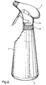
- figure 1 shows a perspective, exploded view of a first preferred embodiment of an assembly according to the present invention;
- figure 2 shows a perspective view of the assembly from figure 1;
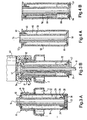
- figure 3a shows a cut away side view of a first preferred embodiment of a device according to the present invention, when sealed;
- figure 3b shows a cut away side view of the device from figure 3a when open; (the embodiment shown in Figures 3a and 3b does not form part of the present invention);
- figure 4a shows a cut away side view of an embodiment of the device according to the present invention when sealed;
- figure 4b shows a cut away side view of the device from figure 4a when open;
- figure 5a shows a cut away side view of a further embodiment of the device according to the present invention when sealed;
- figure 5b shows a cut away side view of the device from figure 5a when open; and
- figure 6 shows a cut away side view of a further embodiment of the device according to the present invention when sealed.
-
- An assembly 1 (figure 1) comprises a
spray bottle dispenser 2, a device 4, in the form of a cartridge, and aspray head 6 having adown tube 8 connected thereto. - The cartridge 4 has a
lip section 10 protruding outwardly from atop wall 12. Thetop wall 12 is provided with anopening 14. - In use, the cartridge 4 is inserted into a
neck section 16 of the bottle 2 (see figure 2) so that the cartridge 4 is suspended by the lip section 10 (see figure 2). - The
spray head 6 is subsequently screwed onto theneck section 16 of the bottle, thedown tube 8 of thespray head 6 extending through a channel (see later) continuous with the top wall opening 14 of the cartridge 4 to terminate in the bottle 2 (see figure 2, figure 3a and 3b). - The cartridge 4 (see figures 3a and 3b), comprises a side wall 18, integral with the
lip section 10 and flexibletop wall 12. -
Top wall opening 14 is continuous with achannel 20 extending through the cartridge 4, whichchannel 20 terminates in a bottom channel opening 22. As shown in figures 1 and 2, thischannel 20 can receive adown tube 8 associated with the spray head. - The side wall 18 and
channel 20 define areservoir area 32, sealed at one end of the device 4 by the flexibletop wall 12 and at the other end of the device by arigid bottom wall 24, extending from the bottom channel opening 22 to the side wall 18. - The
bottom wall 24 comprises a firstelongated part 26 arranged adjacent to thechannel 20, atransverse piece 28 extending from saidelongated part 26 to a downwardly extending sealingpart 30 arranged adjacent to the side wall 18. - On arranging the assembly as shown in figure 1, the
down tube 8 of thespray head 6 is inserted intoopening 14 and pushed through the channel 20 (see figures 3A and 3B). - On securing the
spray head 6 to theneck section 16 of thebottle 2 by means of an interlocking screw thread 19 on the inside of a depending securingpart 34 of thespray head 6, anupper neck section 41 of thedown tube 8 presses down into the raised top wall opening 14 of the cartridge 4, whereby thechannel 20, integrally connected with the flexibletop wall 12, is in turn forced downward, the flexibletop wall 12 being inverted downwards by this action, whereby thechannel 20 pushes therigid bottom wall 24 free of the side wall 18 (see figure 3b) in order to create anexit 42wherethrough concentrate 32 is released to flow into the spray bottle 2 (figure 3b). - Once the
spray bottle 2 has been emptied, instead of now disposing of the spray dispenser assembly, the now empty concentrate cartridge 4 can be simply removed, and following refilling of thespray bottle 2 with water, replaced with a new, fully charged concentrate cartridge 4. - An embodiment of the invention as shown in figures 4a and 4b comprises a
side wall 50 having anupper lip 52, anupper opening 54 continuous with achannel 56 which terminates in alower opening 58. Atop wall section 60 extends between thelip 52 and up and over thechannel 56, to terminate at the edge channel opening 54. Thisupper wall section 60 is substantially rigid, having anextended support part 62 arranged adjacent to thechannel 56. - At the lower end of the
channel 56, a substantially rigidlower wall 64 extends downwardly from thechannel 56 to theouter wall 50. Thechannel 56, thelower wall 64 and theside wall 50 are integral, i.e. they consist of one piece of preferably synthetic material. As with the previous embodiment, theouter wall 50 and thechannel 56 define aconcentrate reservoir area 66. - The
lower wall 64 is more securely attached to thechannel 56 than theouter wall 50. - The
opening 54 extends in the sealed arrangement of the device (figure 4a) above the upper,outer lip 52. - On arranging a spray dispenser assembly, the upper neck section of a down tube presses down into the
opening 54 whereby thechannel 56 andupper wall 60 of the cartridge are pushed down with respect to theside wall 50, whereby in turn the seal between thelower wall 64 and theside wall 50 is broken, whereafter the concentrate within the cartridge is released, through opening 69, i.e. on displacement of thechannel 56 with respect to theouter wall 50, since thelower wall 64 is more weakly integrally attached to theouter wall 50 than thechannel 56, thelower wall 64 ruptures at its juncture with theouter wall 50, due to the rigidity of thelower wall 64, whereby an opening is created (figure 4b), wherethrough concentrate is released into the dispenser. - The further embodiment shown in figures 5a and 5b is similar to the embodiment as shown in figures 4a and figure 4b, except that the
top wall section 70 has a pushingsection 72 integral therewith, which extends downwardly adjacent to the side wall 74 from the top of the cartridge to the bottom thereof, in order to contact, at one side, thelower wall 76 where this is sealed with the side wall 74. Accordingly on pushing down of the channel, this moves downwardly relative to the outer wall, whereby the top wall and accordingly the downwardly extendingsection 72 hereof also move downwardly with respect to the outer wall whereby the bottom wall is pushed open by the topwall pushing section 72.Concentrate 78 is thereby released through opening 79 (see figure 5b). - A further preferred embodiment of the cartridge according to the present invention is shown in figure 6. Here, the
upper wall 80 is substantially T-shaped in cross section and comprises afirst shoulder section 82 which rests on the top of thechannel 84, saidshoulder section 82 is continuous with aflat part 86 extending above alip section 88 of the cartridge side wall 90 whereby an extended depending pushing section 92 depends from under theflat section 86 through thereservoir 94 adjacent the side wall 90 to contact thelower wall 96. On forcing down of theflat section 86, this comes to rest on thelip section 88, whereby thechannel 84 and depending section 92 are forced downwards with respect to the side wall 90, thereby forming an exit between thelower wall 96 and the side wall 90 wherethrough the concentrate can be released. - As shown in figures 5 and 6, the pushing section has the form of cylinder, one end of which has been obliquely cut off, one side of this pushing section is longer than the other, this side contacting the
lower wall 76 in the 'closed' arrangement of the device (see figure 5A, 6). - In the 'open' arrangement of the device (figure 5B), one side of the device consequently has a larger exit through which concentrate is releasable, since the pushing section at this side does not extend into the exit opening.
- The invention is not limited to the above described preferred embodiments, the requested rights are determined by the following claims.
Claims (11)
- Device (4) for storing a liquid, particularly a dilutable concentrate such as a detergent concentrate or the like, said device being co-operable with a spray dispenser bottle (2) and a spray dispenser head (6) which together form a spray dispenser, the device comprising: a top wall (12, 60) and- a bottom wall (64), said top wall and bottom wall being separated by one or more side walls (50), the top and bottom wall each having an opening continuous with a channel (56) running through the device from the top wall opening (54) to the bottom wall opening (58), whereby the top, bottom and sidewalls together with the channel, define at least one reservoir area (66) of the device wherein liquid is storable, said device further comprising exit creating means for creating an exit in said device by relative displacement of parts thereof, whereby liquid is releasable from the reservoir area, characterised in that(a) the bottom wall (64) is substantially rigid and integral with the bottom wall channel opening (58) and the side walls (50) of the device ;(b) the bottom wall (64) is rupturable along a juncture with the side walls (50); and(c) said rupturable juncture is broken by said relative displacement for creating said exit.
- Device according to claim 1, being substantially cylindrical in shape and having such dimensions as to fit within a neck portion (16) of a standard spray dispenser bottle.
- Device according to claims 1 or 2 wherein the channel (56) and the one or more sidewalls (50) are displaceable with respect to one another.
- Device according to claims 1, 2 or 3, wherein the exit creating means comprise the top wall (60), said top wall extending between the top wall opening (54) and the sidewalls (50), to be displaceable between a first position, wherein the liquid is storable in the reservoir area (66) and a second position wherein the liquid is releasable from said reservoir area.
- Device according to any of the previous claims, wherein the top wall (12) is sealably attached with the top wall channel opening (14) and the sidewalls (18) of the device.
- Device according to any of the previous claims, wherein the top wall (12) is integral with the top wall channel opening (14) and the sidewalls (18) and is substantially flexible.
- Device according to any of the previous claims, wherein the top wall further comprises a pushing member (72) which extends from the top wall through the reservoir to contact the bottom wall.
- Device of any of the preceding claims wherein the channel (56) protrudes from the top wall when the bottom wall occupies the closed position.
- Device according to any of the previous claims further comprising a lip section (10, 52) which protrudes outwardly over the side walls from the top wall.
- Assembly (1) comprising a spray dispenser head (6), a device (4) according to any of the preceding claims and a spray container (2).
- Method of introducing a liquid, particularly a concentrate, into a spray container (2) in order to provide a use solution, comprising the steps of:arranging a device (4) according to any of the claims 1-9 in an opening of the spray container,arranging a spray head (6) to fit on the container, whereby on removeably securing the spray head onto the container, the spray head presses down onto the device so that the channel (56) and sidewalls (50) thereof are mutually displaced whereby an exit is created in the bottom wall of the device whereby liquid stored therein flows out of the device and into the container, wherein on mutual displacement of the channel and sidewalls, a rupture forms along a juncture between the integral channel and side walls, which rupture evolves into the exit wherethrough liquid flows into the container.
Priority Applications (1)
| Application Number | Priority Date | Filing Date | Title |
|---|---|---|---|
| EP98913707A EP1012068B1 (en) | 1997-03-27 | 1998-03-10 | Device for storing a liquid, particularly a dilutable concentrate, co-operable with a spray dispenser |
Applications Claiming Priority (4)
| Application Number | Priority Date | Filing Date | Title |
|---|---|---|---|
| EP97200929 | 1997-03-27 | ||
| EP97200929A EP0867381A1 (en) | 1997-03-27 | 1997-03-27 | Device for storing a liquid, particularly a dilutable concentrate, co-operable with a spray dispenser |
| EP98913707A EP1012068B1 (en) | 1997-03-27 | 1998-03-10 | Device for storing a liquid, particularly a dilutable concentrate, co-operable with a spray dispenser |
| PCT/EP1998/001418 WO1998043895A1 (en) | 1997-03-27 | 1998-03-10 | Device for storing a liquid, particularly a dilutable concentrate, co-operable with a spray dispenser |
Publications (2)
| Publication Number | Publication Date |
|---|---|
| EP1012068A1 EP1012068A1 (en) | 2000-06-28 |
| EP1012068B1 true EP1012068B1 (en) | 2002-11-20 |
Family
ID=26070288
Family Applications (2)
| Application Number | Title | Priority Date | Filing Date |
|---|---|---|---|
| EP97200929A Withdrawn EP0867381A1 (en) | 1997-03-27 | 1997-03-27 | Device for storing a liquid, particularly a dilutable concentrate, co-operable with a spray dispenser |
| EP98913707A Expired - Lifetime EP1012068B1 (en) | 1997-03-27 | 1998-03-10 | Device for storing a liquid, particularly a dilutable concentrate, co-operable with a spray dispenser |
Family Applications Before (1)
| Application Number | Title | Priority Date | Filing Date |
|---|---|---|---|
| EP97200929A Withdrawn EP0867381A1 (en) | 1997-03-27 | 1997-03-27 | Device for storing a liquid, particularly a dilutable concentrate, co-operable with a spray dispenser |
Country Status (3)
| Country | Link |
|---|---|
| EP (2) | EP0867381A1 (en) |
| BR (1) | BR9808982A (en) |
| WO (1) | WO1998043895A1 (en) |
Cited By (1)
| Publication number | Priority date | Publication date | Assignee | Title |
|---|---|---|---|---|
| US7331486B2 (en) | 2004-04-06 | 2008-02-19 | Colgate-Palmolive Company | Pump dispenser and cartridge |
Families Citing this family (1)
| Publication number | Priority date | Publication date | Assignee | Title |
|---|---|---|---|---|
| EP2213379A1 (en) | 2009-02-03 | 2010-08-04 | Productos flower S.A. | Closure for containers |
Family Cites Families (6)
| Publication number | Priority date | Publication date | Assignee | Title |
|---|---|---|---|---|
| US3966089A (en) * | 1975-04-25 | 1976-06-29 | Colgate-Palmolive Company | Diluting and dispensing container |
| EP0039693A1 (en) * | 1979-11-16 | 1981-11-18 | Polyfill, Aktiengesellschaft Für Dichtungstechniken | Device for containing products in at least two separate containers and intended to form a mixture or a compound |
| IT1188018B (en) | 1985-08-22 | 1987-12-30 | Jungen Otto | CARTRIDGE CONTAINER FOR CONCENTRATED LIQUIDS OR SIMILAR TO BE IN SOLUTION WITHIN A SPECIAL CONTAINER AT THE TIME OF USE |
| IT207355Z2 (en) | 1986-01-15 | 1988-01-04 | Jurgen Otto | CARTRIDGE CONTAINER INCLUDING TWO OR MORE HERMETICALLY SEPARATE ROOMS CONTAINING SUBSTANCES TO BE SOLUTED ONLY AT THE TIME OF USE. |
| FR2638718B1 (en) * | 1988-11-09 | 1991-02-15 | Oreal | DISPENSING HEAD FOR AN ADDITIVE, INTENDED TO BE MOUNTED ON A CONTAINER, AND CONTAINER PROVIDED WITH SUCH A DISPENSING HEAD |
| IT1259853B (en) * | 1992-12-09 | 1996-03-28 | Bernardino Parise | CONTAINER FOR CONCENTRATED SUBSTANCES IN POWDER OR LIQUID TO BE PUT IN SOLUTION WITHIN A WRAPPER AT THE TIME OF USE |
-
1997
- 1997-03-27 EP EP97200929A patent/EP0867381A1/en not_active Withdrawn
-
1998
- 1998-03-10 EP EP98913707A patent/EP1012068B1/en not_active Expired - Lifetime
- 1998-03-10 WO PCT/EP1998/001418 patent/WO1998043895A1/en active IP Right Grant
- 1998-03-10 BR BR9808982-0A patent/BR9808982A/en not_active Application Discontinuation
Cited By (1)
| Publication number | Priority date | Publication date | Assignee | Title |
|---|---|---|---|---|
| US7331486B2 (en) | 2004-04-06 | 2008-02-19 | Colgate-Palmolive Company | Pump dispenser and cartridge |
Also Published As
| Publication number | Publication date |
|---|---|
| EP0867381A1 (en) | 1998-09-30 |
| BR9808982A (en) | 2000-08-01 |
| WO1998043895A1 (en) | 1998-10-08 |
| EP1012068A1 (en) | 2000-06-28 |
Similar Documents
| Publication | Publication Date | Title |
|---|---|---|
| US6182865B1 (en) | Device for storing a liquid co-operable with a spray dispenser, and spray dispenser comprising said device | |
| CA2560340C (en) | Pump dispenser and sealed cartridge inserted into container and broken by dip tube | |
| US7926682B2 (en) | Apparatus for reconstituting and applying liquids and method of using same | |
| US5328055A (en) | Refillable liquid dispenser with diamond-shaped inner pliant bladder | |
| US8261943B2 (en) | Spray bottle with refill cartridge | |
| WO2001019205A8 (en) | Dispensing pack and machine | |
| US5967379A (en) | Liquid dispenser having a container with a dispensing device | |
| EP0561322B1 (en) | Dropper bottle for two products to be mixed prior to use | |
| EP0156057A2 (en) | Solid cast detergent dispenser with insert for holding noncompatible chemicals | |
| CA2309277C (en) | Concentrate dosing device for refillable spray dispensers | |
| EP1012068B1 (en) | Device for storing a liquid, particularly a dilutable concentrate, co-operable with a spray dispenser | |
| US6360918B1 (en) | Bottle | |
| US5769107A (en) | Valve system, particularly for use with termiticide systems | |
| US5265775A (en) | Aerosol spray container | |
| US4331269A (en) | Nozzle adapter for tilt actuated nozzle down valves | |
| GB2369609A (en) | A Dispensing Container with a Secondary Chamber for Addition of Concentrate | |
| HUT73298A (en) | Refillable package | |
| EP0081022A1 (en) | Aerosol dispensers | |
| GB2610268A (en) | Fragrance refill | |
| JPH0577055U (en) | Cap with storage | |
| CA1313646C (en) | Dispenser pouch for beverage syrups and concentrates | |
| JPH0594150U (en) | A container with a dispenser that allows the contents to be refilled freely |
Legal Events
| Date | Code | Title | Description |
|---|---|---|---|
| PUAI | Public reference made under article 153(3) epc to a published international application that has entered the european phase |
Free format text: ORIGINAL CODE: 0009012 |
|
| 17P | Request for examination filed |
Effective date: 19990826 |
|
| AK | Designated contracting states |
Kind code of ref document: A1 Designated state(s): CH DE ES FR GB IT LI NL SE |
|
| GRAG | Despatch of communication of intention to grant |
Free format text: ORIGINAL CODE: EPIDOS AGRA |
|
| 17Q | First examination report despatched |
Effective date: 20011228 |
|
| GRAG | Despatch of communication of intention to grant |
Free format text: ORIGINAL CODE: EPIDOS AGRA |
|
| GRAH | Despatch of communication of intention to grant a patent |
Free format text: ORIGINAL CODE: EPIDOS IGRA |
|
| GRAH | Despatch of communication of intention to grant a patent |
Free format text: ORIGINAL CODE: EPIDOS IGRA |
|
| GRAA | (expected) grant |
Free format text: ORIGINAL CODE: 0009210 |
|
| RAP1 | Party data changed (applicant data changed or rights of an application transferred) |
Owner name: JOHNSONDIVERSEY, INC. |
|
| AK | Designated contracting states |
Kind code of ref document: B1 Designated state(s): CH DE ES FR GB IT LI NL SE |
|
| REG | Reference to a national code |
Ref country code: GB Ref legal event code: FG4D |
|
| REG | Reference to a national code |
Ref country code: CH Ref legal event code: EP |
|
| REG | Reference to a national code |
Ref country code: CH Ref legal event code: NV Representative=s name: E. BLUM & CO. PATENTANWAELTE |
|
| REF | Corresponds to: |
Ref document number: 69809570 Country of ref document: DE Date of ref document: 20030102 |
|
| ET | Fr: translation filed | ||
| REG | Reference to a national code |
Ref country code: ES Ref legal event code: FG2A Ref document number: 2186146 Country of ref document: ES Kind code of ref document: T3 |
|
| PLBE | No opposition filed within time limit |
Free format text: ORIGINAL CODE: 0009261 |
|
| STAA | Information on the status of an ep patent application or granted ep patent |
Free format text: STATUS: NO OPPOSITION FILED WITHIN TIME LIMIT |
|
| 26N | No opposition filed |
Effective date: 20030821 |
|
| REG | Reference to a national code |
Ref country code: CH Ref legal event code: PFA Owner name: JOHNSONDIVERSEY, INC. Free format text: JOHNSONDIVERSEY, INC.#8310 16TH STREET#STURTEVANT, WISCONSIN 53177-0902 (US) -TRANSFER TO- JOHNSONDIVERSEY, INC.#8310 16TH STREET#STURTEVANT, WISCONSIN 53177-0902 (US) |
|
| REG | Reference to a national code |
Ref country code: CH Ref legal event code: PFA Owner name: DIVERSEY, INC. Free format text: JOHNSONDIVERSEY, INC.#8310 16TH STREET#STURTEVANT, WISCONSIN 53177-0902 (US) -TRANSFER TO- DIVERSEY, INC.#8310 16TH STREET - M/S 509#STURTEVANT, WI 53177-0902 (US) |
|
| REG | Reference to a national code |
Ref country code: NL Ref legal event code: TD Effective date: 20101028 |
|
| REG | Reference to a national code |
Ref country code: FR Ref legal event code: CD |
|
| REG | Reference to a national code |
Ref country code: ES Ref legal event code: PC2A Owner name: DIVERSEY, INC. Effective date: 20110429 |
|
| REG | Reference to a national code |
Ref country code: NL Ref legal event code: PLEX Effective date: 20120724 |
|
| PGFP | Annual fee paid to national office [announced via postgrant information from national office to epo] |
Ref country code: CH Payment date: 20140327 Year of fee payment: 17 Ref country code: SE Payment date: 20140327 Year of fee payment: 17 |
|
| PGFP | Annual fee paid to national office [announced via postgrant information from national office to epo] |
Ref country code: ES Payment date: 20140326 Year of fee payment: 17 Ref country code: IT Payment date: 20140324 Year of fee payment: 17 |
|
| REG | Reference to a national code |
Ref country code: CH Ref legal event code: PL |
|
| PG25 | Lapsed in a contracting state [announced via postgrant information from national office to epo] |
Ref country code: SE Free format text: LAPSE BECAUSE OF NON-PAYMENT OF DUE FEES Effective date: 20150311 |
|
| REG | Reference to a national code |
Ref country code: SE Ref legal event code: EUG |
|
| PG25 | Lapsed in a contracting state [announced via postgrant information from national office to epo] |
Ref country code: IT Free format text: LAPSE BECAUSE OF NON-PAYMENT OF DUE FEES Effective date: 20150310 |
|
| PG25 | Lapsed in a contracting state [announced via postgrant information from national office to epo] |
Ref country code: CH Free format text: LAPSE BECAUSE OF NON-PAYMENT OF DUE FEES Effective date: 20150331 Ref country code: LI Free format text: LAPSE BECAUSE OF NON-PAYMENT OF DUE FEES Effective date: 20150331 |
|
| REG | Reference to a national code |
Ref country code: FR Ref legal event code: PLFP Year of fee payment: 19 |
|
| REG | Reference to a national code |
Ref country code: ES Ref legal event code: FD2A Effective date: 20160428 |
|
| PG25 | Lapsed in a contracting state [announced via postgrant information from national office to epo] |
Ref country code: ES Free format text: LAPSE BECAUSE OF NON-PAYMENT OF DUE FEES Effective date: 20150311 |
|
| REG | Reference to a national code |
Ref country code: FR Ref legal event code: PLFP Year of fee payment: 20 |
|
| PGFP | Annual fee paid to national office [announced via postgrant information from national office to epo] |
Ref country code: FR Payment date: 20170327 Year of fee payment: 20 Ref country code: NL Payment date: 20170326 Year of fee payment: 20 |
|
| PGFP | Annual fee paid to national office [announced via postgrant information from national office to epo] |
Ref country code: GB Payment date: 20170327 Year of fee payment: 20 |
|
| PGFP | Annual fee paid to national office [announced via postgrant information from national office to epo] |
Ref country code: DE Payment date: 20170329 Year of fee payment: 20 |
|
| REG | Reference to a national code |
Ref country code: DE Ref legal event code: R071 Ref document number: 69809570 Country of ref document: DE |
|
| REG | Reference to a national code |
Ref country code: NL Ref legal event code: MK Effective date: 20180309 |
|
| REG | Reference to a national code |
Ref country code: GB Ref legal event code: PE20 Expiry date: 20180309 |
|
| PG25 | Lapsed in a contracting state [announced via postgrant information from national office to epo] |
Ref country code: GB Free format text: LAPSE BECAUSE OF EXPIRATION OF PROTECTION Effective date: 20180309 |