EP1011544B1 - Metacarpal-phalangeal joint replacement - Google Patents
Metacarpal-phalangeal joint replacement Download PDFInfo
- Publication number
- EP1011544B1 EP1011544B1 EP97948149A EP97948149A EP1011544B1 EP 1011544 B1 EP1011544 B1 EP 1011544B1 EP 97948149 A EP97948149 A EP 97948149A EP 97948149 A EP97948149 A EP 97948149A EP 1011544 B1 EP1011544 B1 EP 1011544B1
- Authority
- EP
- European Patent Office
- Prior art keywords
- phalangeal
- head
- metacarpal
- articular
- dorsal
- Prior art date
- Legal status (The legal status is an assumption and is not a legal conclusion. Google has not performed a legal analysis and makes no representation as to the accuracy of the status listed.)
- Expired - Lifetime
Links
Images

Classifications
-
- A—HUMAN NECESSITIES
- A61—MEDICAL OR VETERINARY SCIENCE; HYGIENE
- A61F—FILTERS IMPLANTABLE INTO BLOOD VESSELS; PROSTHESES; DEVICES PROVIDING PATENCY TO, OR PREVENTING COLLAPSING OF, TUBULAR STRUCTURES OF THE BODY, e.g. STENTS; ORTHOPAEDIC, NURSING OR CONTRACEPTIVE DEVICES; FOMENTATION; TREATMENT OR PROTECTION OF EYES OR EARS; BANDAGES, DRESSINGS OR ABSORBENT PADS; FIRST-AID KITS
- A61F2/00—Filters implantable into blood vessels; Prostheses, i.e. artificial substitutes or replacements for parts of the body; Appliances for connecting them with the body; Devices providing patency to, or preventing collapsing of, tubular structures of the body, e.g. stents
- A61F2/02—Prostheses implantable into the body
- A61F2/30—Joints
- A61F2/42—Joints for wrists or ankles; for hands, e.g. fingers; for feet, e.g. toes
- A61F2/4241—Joints for wrists or ankles; for hands, e.g. fingers; for feet, e.g. toes for hands, e.g. fingers
-
- A—HUMAN NECESSITIES
- A61—MEDICAL OR VETERINARY SCIENCE; HYGIENE
- A61F—FILTERS IMPLANTABLE INTO BLOOD VESSELS; PROSTHESES; DEVICES PROVIDING PATENCY TO, OR PREVENTING COLLAPSING OF, TUBULAR STRUCTURES OF THE BODY, e.g. STENTS; ORTHOPAEDIC, NURSING OR CONTRACEPTIVE DEVICES; FOMENTATION; TREATMENT OR PROTECTION OF EYES OR EARS; BANDAGES, DRESSINGS OR ABSORBENT PADS; FIRST-AID KITS
- A61F2/00—Filters implantable into blood vessels; Prostheses, i.e. artificial substitutes or replacements for parts of the body; Appliances for connecting them with the body; Devices providing patency to, or preventing collapsing of, tubular structures of the body, e.g. stents
- A61F2/02—Prostheses implantable into the body
- A61F2/30—Joints
- A61F2/30767—Special external or bone-contacting surface, e.g. coating for improving bone ingrowth
-
- A—HUMAN NECESSITIES
- A61—MEDICAL OR VETERINARY SCIENCE; HYGIENE
- A61F—FILTERS IMPLANTABLE INTO BLOOD VESSELS; PROSTHESES; DEVICES PROVIDING PATENCY TO, OR PREVENTING COLLAPSING OF, TUBULAR STRUCTURES OF THE BODY, e.g. STENTS; ORTHOPAEDIC, NURSING OR CONTRACEPTIVE DEVICES; FOMENTATION; TREATMENT OR PROTECTION OF EYES OR EARS; BANDAGES, DRESSINGS OR ABSORBENT PADS; FIRST-AID KITS
- A61F2/00—Filters implantable into blood vessels; Prostheses, i.e. artificial substitutes or replacements for parts of the body; Appliances for connecting them with the body; Devices providing patency to, or preventing collapsing of, tubular structures of the body, e.g. stents
- A61F2/02—Prostheses implantable into the body
- A61F2/30—Joints
- A61F2/3094—Designing or manufacturing processes
- A61F2/30965—Reinforcing the prosthesis by embedding particles or fibres during moulding or dipping
-
- A—HUMAN NECESSITIES
- A61—MEDICAL OR VETERINARY SCIENCE; HYGIENE
- A61F—FILTERS IMPLANTABLE INTO BLOOD VESSELS; PROSTHESES; DEVICES PROVIDING PATENCY TO, OR PREVENTING COLLAPSING OF, TUBULAR STRUCTURES OF THE BODY, e.g. STENTS; ORTHOPAEDIC, NURSING OR CONTRACEPTIVE DEVICES; FOMENTATION; TREATMENT OR PROTECTION OF EYES OR EARS; BANDAGES, DRESSINGS OR ABSORBENT PADS; FIRST-AID KITS
- A61F2/00—Filters implantable into blood vessels; Prostheses, i.e. artificial substitutes or replacements for parts of the body; Appliances for connecting them with the body; Devices providing patency to, or preventing collapsing of, tubular structures of the body, e.g. stents
- A61F2/02—Prostheses implantable into the body
- A61F2/30—Joints
- A61F2002/30001—Additional features of subject-matter classified in A61F2/28, A61F2/30 and subgroups thereof
- A61F2002/30108—Shapes
- A61F2002/3011—Cross-sections or two-dimensional shapes
- A61F2002/30112—Rounded shapes, e.g. with rounded corners
- A61F2002/30125—Rounded shapes, e.g. with rounded corners elliptical or oval
-
- A—HUMAN NECESSITIES
- A61—MEDICAL OR VETERINARY SCIENCE; HYGIENE
- A61F—FILTERS IMPLANTABLE INTO BLOOD VESSELS; PROSTHESES; DEVICES PROVIDING PATENCY TO, OR PREVENTING COLLAPSING OF, TUBULAR STRUCTURES OF THE BODY, e.g. STENTS; ORTHOPAEDIC, NURSING OR CONTRACEPTIVE DEVICES; FOMENTATION; TREATMENT OR PROTECTION OF EYES OR EARS; BANDAGES, DRESSINGS OR ABSORBENT PADS; FIRST-AID KITS
- A61F2/00—Filters implantable into blood vessels; Prostheses, i.e. artificial substitutes or replacements for parts of the body; Appliances for connecting them with the body; Devices providing patency to, or preventing collapsing of, tubular structures of the body, e.g. stents
- A61F2/02—Prostheses implantable into the body
- A61F2/30—Joints
- A61F2002/30001—Additional features of subject-matter classified in A61F2/28, A61F2/30 and subgroups thereof
- A61F2002/30108—Shapes
- A61F2002/3011—Cross-sections or two-dimensional shapes
- A61F2002/30138—Convex polygonal shapes
- A61F2002/30158—Convex polygonal shapes trapezoidal
-
- A—HUMAN NECESSITIES
- A61—MEDICAL OR VETERINARY SCIENCE; HYGIENE
- A61F—FILTERS IMPLANTABLE INTO BLOOD VESSELS; PROSTHESES; DEVICES PROVIDING PATENCY TO, OR PREVENTING COLLAPSING OF, TUBULAR STRUCTURES OF THE BODY, e.g. STENTS; ORTHOPAEDIC, NURSING OR CONTRACEPTIVE DEVICES; FOMENTATION; TREATMENT OR PROTECTION OF EYES OR EARS; BANDAGES, DRESSINGS OR ABSORBENT PADS; FIRST-AID KITS
- A61F2/00—Filters implantable into blood vessels; Prostheses, i.e. artificial substitutes or replacements for parts of the body; Appliances for connecting them with the body; Devices providing patency to, or preventing collapsing of, tubular structures of the body, e.g. stents
- A61F2/02—Prostheses implantable into the body
- A61F2/30—Joints
- A61F2002/30001—Additional features of subject-matter classified in A61F2/28, A61F2/30 and subgroups thereof
- A61F2002/30316—The prosthesis having different structural features at different locations within the same prosthesis; Connections between prosthetic parts; Special structural features of bone or joint prostheses not otherwise provided for
- A61F2002/30535—Special structural features of bone or joint prostheses not otherwise provided for
- A61F2002/30604—Special structural features of bone or joint prostheses not otherwise provided for modular
- A61F2002/30616—Sets comprising a plurality of prosthetic parts of different sizes or orientations
-
- A—HUMAN NECESSITIES
- A61—MEDICAL OR VETERINARY SCIENCE; HYGIENE
- A61F—FILTERS IMPLANTABLE INTO BLOOD VESSELS; PROSTHESES; DEVICES PROVIDING PATENCY TO, OR PREVENTING COLLAPSING OF, TUBULAR STRUCTURES OF THE BODY, e.g. STENTS; ORTHOPAEDIC, NURSING OR CONTRACEPTIVE DEVICES; FOMENTATION; TREATMENT OR PROTECTION OF EYES OR EARS; BANDAGES, DRESSINGS OR ABSORBENT PADS; FIRST-AID KITS
- A61F2/00—Filters implantable into blood vessels; Prostheses, i.e. artificial substitutes or replacements for parts of the body; Appliances for connecting them with the body; Devices providing patency to, or preventing collapsing of, tubular structures of the body, e.g. stents
- A61F2/02—Prostheses implantable into the body
- A61F2/30—Joints
- A61F2002/30001—Additional features of subject-matter classified in A61F2/28, A61F2/30 and subgroups thereof
- A61F2002/30621—Features concerning the anatomical functioning or articulation of the prosthetic joint
- A61F2002/30649—Ball-and-socket joints
- A61F2002/3065—Details of the ball-shaped head
- A61F2002/30652—Special cut-outs, e.g. flat or grooved cut-outs
-
- A—HUMAN NECESSITIES
- A61—MEDICAL OR VETERINARY SCIENCE; HYGIENE
- A61F—FILTERS IMPLANTABLE INTO BLOOD VESSELS; PROSTHESES; DEVICES PROVIDING PATENCY TO, OR PREVENTING COLLAPSING OF, TUBULAR STRUCTURES OF THE BODY, e.g. STENTS; ORTHOPAEDIC, NURSING OR CONTRACEPTIVE DEVICES; FOMENTATION; TREATMENT OR PROTECTION OF EYES OR EARS; BANDAGES, DRESSINGS OR ABSORBENT PADS; FIRST-AID KITS
- A61F2/00—Filters implantable into blood vessels; Prostheses, i.e. artificial substitutes or replacements for parts of the body; Appliances for connecting them with the body; Devices providing patency to, or preventing collapsing of, tubular structures of the body, e.g. stents
- A61F2/02—Prostheses implantable into the body
- A61F2/30—Joints
- A61F2002/30001—Additional features of subject-matter classified in A61F2/28, A61F2/30 and subgroups thereof
- A61F2002/30667—Features concerning an interaction with the environment or a particular use of the prosthesis
- A61F2002/30673—Lubricating means, e.g. synovial pocket
-
- A—HUMAN NECESSITIES
- A61—MEDICAL OR VETERINARY SCIENCE; HYGIENE
- A61F—FILTERS IMPLANTABLE INTO BLOOD VESSELS; PROSTHESES; DEVICES PROVIDING PATENCY TO, OR PREVENTING COLLAPSING OF, TUBULAR STRUCTURES OF THE BODY, e.g. STENTS; ORTHOPAEDIC, NURSING OR CONTRACEPTIVE DEVICES; FOMENTATION; TREATMENT OR PROTECTION OF EYES OR EARS; BANDAGES, DRESSINGS OR ABSORBENT PADS; FIRST-AID KITS
- A61F2/00—Filters implantable into blood vessels; Prostheses, i.e. artificial substitutes or replacements for parts of the body; Appliances for connecting them with the body; Devices providing patency to, or preventing collapsing of, tubular structures of the body, e.g. stents
- A61F2/02—Prostheses implantable into the body
- A61F2/30—Joints
- A61F2002/30001—Additional features of subject-matter classified in A61F2/28, A61F2/30 and subgroups thereof
- A61F2002/30667—Features concerning an interaction with the environment or a particular use of the prosthesis
- A61F2002/30688—Means for allowing passage or sliding of tendons or ligaments
-
- A—HUMAN NECESSITIES
- A61—MEDICAL OR VETERINARY SCIENCE; HYGIENE
- A61F—FILTERS IMPLANTABLE INTO BLOOD VESSELS; PROSTHESES; DEVICES PROVIDING PATENCY TO, OR PREVENTING COLLAPSING OF, TUBULAR STRUCTURES OF THE BODY, e.g. STENTS; ORTHOPAEDIC, NURSING OR CONTRACEPTIVE DEVICES; FOMENTATION; TREATMENT OR PROTECTION OF EYES OR EARS; BANDAGES, DRESSINGS OR ABSORBENT PADS; FIRST-AID KITS
- A61F2/00—Filters implantable into blood vessels; Prostheses, i.e. artificial substitutes or replacements for parts of the body; Appliances for connecting them with the body; Devices providing patency to, or preventing collapsing of, tubular structures of the body, e.g. stents
- A61F2/02—Prostheses implantable into the body
- A61F2/30—Joints
- A61F2002/30001—Additional features of subject-matter classified in A61F2/28, A61F2/30 and subgroups thereof
- A61F2002/30667—Features concerning an interaction with the environment or a particular use of the prosthesis
- A61F2002/30706—Features concerning an interaction with the environment or a particular use of the prosthesis specially designed for children, e.g. having means for adjusting to their growth
-
- A—HUMAN NECESSITIES
- A61—MEDICAL OR VETERINARY SCIENCE; HYGIENE
- A61F—FILTERS IMPLANTABLE INTO BLOOD VESSELS; PROSTHESES; DEVICES PROVIDING PATENCY TO, OR PREVENTING COLLAPSING OF, TUBULAR STRUCTURES OF THE BODY, e.g. STENTS; ORTHOPAEDIC, NURSING OR CONTRACEPTIVE DEVICES; FOMENTATION; TREATMENT OR PROTECTION OF EYES OR EARS; BANDAGES, DRESSINGS OR ABSORBENT PADS; FIRST-AID KITS
- A61F2/00—Filters implantable into blood vessels; Prostheses, i.e. artificial substitutes or replacements for parts of the body; Appliances for connecting them with the body; Devices providing patency to, or preventing collapsing of, tubular structures of the body, e.g. stents
- A61F2/02—Prostheses implantable into the body
- A61F2/30—Joints
- A61F2/30767—Special external or bone-contacting surface, e.g. coating for improving bone ingrowth
- A61F2/30771—Special external or bone-contacting surface, e.g. coating for improving bone ingrowth applied in original prostheses, e.g. holes or grooves
- A61F2002/3082—Grooves
-
- A—HUMAN NECESSITIES
- A61—MEDICAL OR VETERINARY SCIENCE; HYGIENE
- A61F—FILTERS IMPLANTABLE INTO BLOOD VESSELS; PROSTHESES; DEVICES PROVIDING PATENCY TO, OR PREVENTING COLLAPSING OF, TUBULAR STRUCTURES OF THE BODY, e.g. STENTS; ORTHOPAEDIC, NURSING OR CONTRACEPTIVE DEVICES; FOMENTATION; TREATMENT OR PROTECTION OF EYES OR EARS; BANDAGES, DRESSINGS OR ABSORBENT PADS; FIRST-AID KITS
- A61F2/00—Filters implantable into blood vessels; Prostheses, i.e. artificial substitutes or replacements for parts of the body; Appliances for connecting them with the body; Devices providing patency to, or preventing collapsing of, tubular structures of the body, e.g. stents
- A61F2/02—Prostheses implantable into the body
- A61F2/30—Joints
- A61F2/30767—Special external or bone-contacting surface, e.g. coating for improving bone ingrowth
- A61F2002/30934—Special articulating surfaces
-
- A—HUMAN NECESSITIES
- A61—MEDICAL OR VETERINARY SCIENCE; HYGIENE
- A61F—FILTERS IMPLANTABLE INTO BLOOD VESSELS; PROSTHESES; DEVICES PROVIDING PATENCY TO, OR PREVENTING COLLAPSING OF, TUBULAR STRUCTURES OF THE BODY, e.g. STENTS; ORTHOPAEDIC, NURSING OR CONTRACEPTIVE DEVICES; FOMENTATION; TREATMENT OR PROTECTION OF EYES OR EARS; BANDAGES, DRESSINGS OR ABSORBENT PADS; FIRST-AID KITS
- A61F2/00—Filters implantable into blood vessels; Prostheses, i.e. artificial substitutes or replacements for parts of the body; Appliances for connecting them with the body; Devices providing patency to, or preventing collapsing of, tubular structures of the body, e.g. stents
- A61F2/02—Prostheses implantable into the body
- A61F2/30—Joints
- A61F2/42—Joints for wrists or ankles; for hands, e.g. fingers; for feet, e.g. toes
- A61F2/4241—Joints for wrists or ankles; for hands, e.g. fingers; for feet, e.g. toes for hands, e.g. fingers
- A61F2002/4251—Joints for wrists or ankles; for hands, e.g. fingers; for feet, e.g. toes for hands, e.g. fingers for metacarpo-phalangeal joints, i.e. MCP or MP joints, e.g. knuckle joints
-
- A—HUMAN NECESSITIES
- A61—MEDICAL OR VETERINARY SCIENCE; HYGIENE
- A61F—FILTERS IMPLANTABLE INTO BLOOD VESSELS; PROSTHESES; DEVICES PROVIDING PATENCY TO, OR PREVENTING COLLAPSING OF, TUBULAR STRUCTURES OF THE BODY, e.g. STENTS; ORTHOPAEDIC, NURSING OR CONTRACEPTIVE DEVICES; FOMENTATION; TREATMENT OR PROTECTION OF EYES OR EARS; BANDAGES, DRESSINGS OR ABSORBENT PADS; FIRST-AID KITS
- A61F2/00—Filters implantable into blood vessels; Prostheses, i.e. artificial substitutes or replacements for parts of the body; Appliances for connecting them with the body; Devices providing patency to, or preventing collapsing of, tubular structures of the body, e.g. stents
- A61F2/02—Prostheses implantable into the body
- A61F2/30—Joints
- A61F2/46—Special tools or methods for implanting or extracting artificial joints, accessories, bone grafts or substitutes, or particular adaptations therefor
- A61F2002/4631—Special tools or methods for implanting or extracting artificial joints, accessories, bone grafts or substitutes, or particular adaptations therefor the prosthesis being specially adapted for being cemented
-
- A—HUMAN NECESSITIES
- A61—MEDICAL OR VETERINARY SCIENCE; HYGIENE
- A61F—FILTERS IMPLANTABLE INTO BLOOD VESSELS; PROSTHESES; DEVICES PROVIDING PATENCY TO, OR PREVENTING COLLAPSING OF, TUBULAR STRUCTURES OF THE BODY, e.g. STENTS; ORTHOPAEDIC, NURSING OR CONTRACEPTIVE DEVICES; FOMENTATION; TREATMENT OR PROTECTION OF EYES OR EARS; BANDAGES, DRESSINGS OR ABSORBENT PADS; FIRST-AID KITS
- A61F2230/00—Geometry of prostheses classified in groups A61F2/00 - A61F2/26 or A61F2/82 or A61F9/00 or A61F11/00 or subgroups thereof
- A61F2230/0002—Two-dimensional shapes, e.g. cross-sections
- A61F2230/0004—Rounded shapes, e.g. with rounded corners
- A61F2230/0008—Rounded shapes, e.g. with rounded corners elliptical or oval
-
- A—HUMAN NECESSITIES
- A61—MEDICAL OR VETERINARY SCIENCE; HYGIENE
- A61F—FILTERS IMPLANTABLE INTO BLOOD VESSELS; PROSTHESES; DEVICES PROVIDING PATENCY TO, OR PREVENTING COLLAPSING OF, TUBULAR STRUCTURES OF THE BODY, e.g. STENTS; ORTHOPAEDIC, NURSING OR CONTRACEPTIVE DEVICES; FOMENTATION; TREATMENT OR PROTECTION OF EYES OR EARS; BANDAGES, DRESSINGS OR ABSORBENT PADS; FIRST-AID KITS
- A61F2230/00—Geometry of prostheses classified in groups A61F2/00 - A61F2/26 or A61F2/82 or A61F9/00 or A61F11/00 or subgroups thereof
- A61F2230/0002—Two-dimensional shapes, e.g. cross-sections
- A61F2230/0017—Angular shapes
- A61F2230/0026—Angular shapes trapezoidal
-
- A—HUMAN NECESSITIES
- A61—MEDICAL OR VETERINARY SCIENCE; HYGIENE
- A61F—FILTERS IMPLANTABLE INTO BLOOD VESSELS; PROSTHESES; DEVICES PROVIDING PATENCY TO, OR PREVENTING COLLAPSING OF, TUBULAR STRUCTURES OF THE BODY, e.g. STENTS; ORTHOPAEDIC, NURSING OR CONTRACEPTIVE DEVICES; FOMENTATION; TREATMENT OR PROTECTION OF EYES OR EARS; BANDAGES, DRESSINGS OR ABSORBENT PADS; FIRST-AID KITS
- A61F2250/00—Special features of prostheses classified in groups A61F2/00 - A61F2/26 or A61F2/82 or A61F9/00 or A61F11/00 or subgroups thereof
- A61F2250/0058—Additional features; Implant or prostheses properties not otherwise provided for
- A61F2250/0082—Additional features; Implant or prostheses properties not otherwise provided for specially designed for children, e.g. having means for adjusting to their growth
-
- A—HUMAN NECESSITIES
- A61—MEDICAL OR VETERINARY SCIENCE; HYGIENE
- A61F—FILTERS IMPLANTABLE INTO BLOOD VESSELS; PROSTHESES; DEVICES PROVIDING PATENCY TO, OR PREVENTING COLLAPSING OF, TUBULAR STRUCTURES OF THE BODY, e.g. STENTS; ORTHOPAEDIC, NURSING OR CONTRACEPTIVE DEVICES; FOMENTATION; TREATMENT OR PROTECTION OF EYES OR EARS; BANDAGES, DRESSINGS OR ABSORBENT PADS; FIRST-AID KITS
- A61F2310/00—Prostheses classified in A61F2/28 or A61F2/30 - A61F2/44 being constructed from or coated with a particular material
- A61F2310/00005—The prosthesis being constructed from a particular material
- A61F2310/00161—Carbon; Graphite
- A61F2310/00173—Graphite
-
- A—HUMAN NECESSITIES
- A61—MEDICAL OR VETERINARY SCIENCE; HYGIENE
- A61F—FILTERS IMPLANTABLE INTO BLOOD VESSELS; PROSTHESES; DEVICES PROVIDING PATENCY TO, OR PREVENTING COLLAPSING OF, TUBULAR STRUCTURES OF THE BODY, e.g. STENTS; ORTHOPAEDIC, NURSING OR CONTRACEPTIVE DEVICES; FOMENTATION; TREATMENT OR PROTECTION OF EYES OR EARS; BANDAGES, DRESSINGS OR ABSORBENT PADS; FIRST-AID KITS
- A61F2310/00—Prostheses classified in A61F2/28 or A61F2/30 - A61F2/44 being constructed from or coated with a particular material
- A61F2310/00389—The prosthesis being coated or covered with a particular material
- A61F2310/00574—Coating or prosthesis-covering structure made of carbon, e.g. of pyrocarbon
-
- A—HUMAN NECESSITIES
- A61—MEDICAL OR VETERINARY SCIENCE; HYGIENE
- A61F—FILTERS IMPLANTABLE INTO BLOOD VESSELS; PROSTHESES; DEVICES PROVIDING PATENCY TO, OR PREVENTING COLLAPSING OF, TUBULAR STRUCTURES OF THE BODY, e.g. STENTS; ORTHOPAEDIC, NURSING OR CONTRACEPTIVE DEVICES; FOMENTATION; TREATMENT OR PROTECTION OF EYES OR EARS; BANDAGES, DRESSINGS OR ABSORBENT PADS; FIRST-AID KITS
- A61F2310/00—Prostheses classified in A61F2/28 or A61F2/30 - A61F2/44 being constructed from or coated with a particular material
- A61F2310/00389—The prosthesis being coated or covered with a particular material
- A61F2310/00592—Coating or prosthesis-covering structure made of ceramics or of ceramic-like compounds
- A61F2310/00796—Coating or prosthesis-covering structure made of a phosphorus-containing compound, e.g. hydroxy(l)apatite
Abstract
Description
- The present invention generally relates to prosthetic devices and more particularly to devices for replacement of the metacarpal-phalangeal (MP) joint of a human finger.
- US-A-4,231,121 discloses the features in the preamble of claim 1.
- The first elongated bone (metacarpal) at the base of each finger is connected to a proximal phalangeal bone through the metacarpal-phalangeal (MP) joint. This particular joint can be flexed or extended independently of the proximal or distal interphalangeal joint. This variable reciprocal motion, along with the opposability of the thumb, allows for the grasping of objects and the performance of daily functions which are of critical importance to humans. Damage to the MP joint through physical injury or disease can therefore be a severe physiological burden to inflicted humans.
- Rheumatoid arthritis (RA), degenerative arthritis, and post-traumatic arthrosis of the MP joint cause interminable pain and poor function of the finger. Patients who have mild symptoms often respond to rest, immobilization, non-steroidal anti-inflammatory drugs, or intra-articular injections of steroids. However, patients who have more severe forms of arthritis may require total joint replacement of the MP joint.
- The most common deformity in patients suffering from RA is induced by synovitis of the MP joint which often causes a narrowing of the articular cartilage of the MP joint and attenuation of the collateral ligament structure. The result is often palmar subluxation-dislocation of the proximal phalangeal bone which is caused by a laxity of the flexor complex on the palmar aspect of the MP joint. After loosening of this flexor complex, the action of the flexor tendons provides a dynamic force that palmarly subluxes-dislocates the proximal phalangeal bone. In addition, there is often a secondary loss of cartilage height by erosion and frequently a secondary change in bony architecture, producing a flattening of the metacarpal head and erosion of the dorsal lip of the proximal phalanx. The usual solution is installation of a MP prosthetic joint, see Linscheid et al., "Total Joint Arthroplasty", Mayo Clin. Proc., 54:516-526 (1979); however, in such a case, there is a need for a replacement joint which resists subluxation-dislocation of the proximal phalangeal bone in the palmar direction.
- A second important design consideration for MP prosthetic joints is minimizing the wear between the mating articulating surfaces. Mating surfaces may conform to such an extent that biological fluids which would normally provide joint lubrication are expressed from the MP prosthetic joint. The resulting "dry joint" may experience increased friction between the congrue articulating surfaces, as well as create an uncomfortable grinding and/or "squeaky" sensation to the recipient. Increased friction between the congruent articulating surfaces may result in increased wear of the MP prosthetic joint, thereby decreasing the service life of the prothesis. A MP prosthetic joint should preferably avoid exclusion of biological fluid from the congruent mating articulating surfaces.
- Another important design consideration for MP prosthetic joints is providing a generally free path for the collateral ligaments which run along each lateral side of the MP joint and for the palmar ligaments or plate. The collateral ligaments of the MP joint comprise both fan-like collateral ligaments and cord-like collateral ligaments. The fan-like collateral ligaments insert at both sides of the distal portion of the first metacarpal bone and serve to support the palmar plate (sometimes called the volar plate) which attaches to the volar aspect of the proximal phalanx and forms a part of the MP overall joint. The cord-like collateral ligaments also insert in shallow depressions at both sides of the dorsal aspect of the distal portion of the first metacarpal bone and cross the MP joint to insert at the lateral volar sides of the proximally phalangeal bone. The cord-like ligaments are slack in extension of the MP joint, allowing for radial-ulnar motion, and are taut during flexion motion, prohibiting radial-ulnar motion. Proper MP prosthetic joint design should have concern for such ligaments.
- Accordingly it is the object of the present invention to construct an improved MP joint prosthesis which allows essentially original and natural function to be restored to a damaged finger. To restore natural motion to a damaged finger, the MP prosthetic joint design should provide a free path for the collateral ligaments to run from the distally facing dorsal articular portion of the first metacarpal bone to the proximally facing palmar articular portion of the proximal phalangeal bone.
- According to the present invention there is provided a prosthetic device designed for replacement of a MP joint of a human finger comprising
a metacarpal element having a stem portion which is shaped to be received within a metacarpal bone cavity, and an articular head portion, which head portion has a generally ball-shaped surface to replace the distal articular portion of a metacarpal bone and has a flat collar section at the end of said stem portion, said flat section being oriented at a dorsal angle between 110° and 120° to the axis of said stem portion thereof; and a phalangeal element having a stem portion, which is shaped to be received within a phalangeal bone cavity, and an articular head portion, which has a concave surface shaped to conform to said ball-shaped surface and is designed to replace a corresponding articular portion of a phalangeal bone; and
characterized in that: - said metacarpal element's articular head is provided with relief means in the form of a flat surface located on each lateral side thereof which interrupts said otherwise ball-shaped surface so that, at the location of said collar, said ball-shaped head has a spherical arc of 30° to 90° on the dorsal side of the equator and a spherical arc of 120° to 170° on the volar side, whereby a generally free path is provided to allow the collateral ligaments to run without interference from a dorsal/proximal edge of said metacarpal element's articular head to a palmar/distal edge of said phalangeal element's articular head. The articulating surfaces are substantially congruent, except for the optional provision of a noncongruent groove means. Such groove means is preferably located in the phalangeal member's articular surface, and more preferably, it includes two generally perpendicular grooves, each oriented at about 45° to the plane of flexion-extension motion. Such grooves facilitate synovial lubricating fluid access to the articulating surfaces each time the MP joint member moves relative to each other.
-
- The phalangeal member's proximal articular head combines a generally elliptically shaped collar with a concave articulating surface of spherical curvature in a manner which provides a dorsal protrusion and a shape along its palmar aspect which does not disrupt the attachment sites of the collateral ligaments, avoids interference with the palmar ligament during flexion and provides a free path for the collateral ligaments. Also, surrounding the phalangeal member's concave, generally spherical surface is a rim in the form of a generally toroidal surface which forms a part of the dorsal protrusion that extends over the articular surface of the head of the metacarpal member by a sufficient distance so as to resist volar subluxation-dislocation of the proximal phalangeal bone in the palmar direction. This toroidal rim may be tangent to a plane, or preferably, the head of the phalangeal member may be shaped so that this rim is tangent to a circular cylinder so that the lateral portions of the rim extend in a proximal direction so that the lateral regions of the head provide greater capture of the spherical head of the metacarpal element, thereby enlarging the region of the spherical surface where there is articulating contact and increasing the stability of the joint.
- The convex, generally spherical head of the metacarpal member preferably has a relief means in the form of a pair of reliefs located laterally thereof. These reliefs provide generally free paths for the fan-like and cord-like collateral ligaments which generally run along each lateral side of the MP joint.
- The improved MP prosthetic joint realizes the aforementioned objects, features and advantages in a manner that is clearly evident from a thorough consideration of the detailed description when taken in conjunction with the drawings wherein there is shown and described illustrative embodiments of the invention.
-
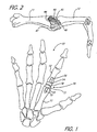
- FIG. 1 is a schematic view, partially in section, of the human hand bone anatomy showing the general placement of an artificial MP joint.
- FIG. 2 is a side elevation view illustrating the arrangement of the collateral ligaments of the normal MP joint when the first metacarpal bone and proximal phalangeal bone are in full extension.
- FIG. 3 is a side perspective view of an MP prosthetic joint embodying various features of the present invention showing the metacarpal element and phalangeal element in full extension, and particularly showing one relief which is cut laterally in the head of the metacarpal element.
- FIG. 3A is a side elevation view of the MP joint of FIG. 3 looking from the opposite side.
- FIG. 4 is a perspective view of a phalangeal element of FIG. 3.
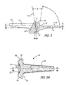
- FIG. 5 is a side, partial sectional view of the MP replacement joint shown in FIG. 3A, illustrating various relevant angles of its construction.
- FIG. 5A is a top view of the phalangeal element with a portion broken away and shown in section.
- FIG. 5B is a side section view taken along
line 5B-5B of FIG. 5A. - FIG. 5C is a rear section view of the phalangeal
element taken along
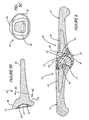
line 5C-5C of FIG. 5B. - FIG. 6 is a side view, in partial section, of a first metacarpal bone and a proximal phalangeal bone in full extension with the replacement MP joint of FIG. 3 inserted therein.
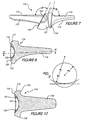
- FIG. 7 is a side elevation view, generally similar to FIG. 3A, of an alternative version of an MP prosthetic joint.
- FIG. 8 is a sectional view, similar to FIG. 5B, of the phalangeal element of the MP joint shown in FIG. 7.
- FIG. 9 is a schematic view showing the curvature of the proximal surface of the head of the phalangeal element relative to the spherical surface of the metacarpal element.
- FIG. 10 is a sectional view, which is generally similar to FIG. 5A, taken generally along the line 10-10 of FIG. 8.
-
- The present invention is directed to a joint prosthesis for the replacement of a diseased or damaged human joint. The preferred prosthesis is designed for permanent implantation in the human hand.
- Because of the unique anatomy around the metacarpal-phalangeal joint, this joint can be flexed or extended independently of the proximal or distal interphalangeal joint. This variable reciprocal motion, along with the opposability of the thumb, is the hallmark of human dexterity.
- In FIG. 1, a human
right hand 10 is shown from the palmar perspective. The index finger contains a schematic representation of a MP prosthetic joint 19 located between the firstmetacarpal bone 11 and the proximalphalangeal bone 12. The MP prosthetic joint 19 comprises a first ormetacarpal element 13, which is implanted in the firstmetacarpal bone 11, and a second orphalangeal element 14 implanted in the proximalphalangeal bone 12. - The
metacarpal element 13 includes astem portion 15, which is shaped to be received within the marrow or medullary cavity of the firstmetacarpal bone 11, and anarticular head 17 which has a generally ball-shaped surface designed to replace the articular head of the firstmetacarpal bone 11. Thephalangeal element 14 includes astem portion 16, which is shaped to be received within the marrow or medullary cavity of the proximalphalangeal bone 12, and anarticular head 18 which is generally socket-shaped and proportioned to conform to the metacarpal element's generally ball-shaped surface and replace the corresponding articular head of the proximalphalangeal bone 12. The stems 15 and 16 are schematically shown with optional grooves as are well known in this art. - Shown in FIG. 3 is a MP prosthetic joint 19 embodying various features, wherein the
metacarpal element 13 and thephalangeal element 14 are respectively formed at their ends with theheads surfaces phalangeal element 14 has a socket-shapedarticulation surface 22 which is shaped to conform to a generally spherical or ball-shaped articulation surface of themetacarpal element 13, which is preferably substantially hemispherical. Thehead 17 is preferably a section of a sphere that extends about 5° to 10° of arc past the equator, and the illustratedhead 17 has a major arc of about 190°, as best seen in FIGS. 3A and 5. - In the preferred embodiment, the
articulation surface 22 of thephalangeal element 14 is a concave, surface of spherical curvature which is proportioned to conform with the metacarpal element's convexhemispherical surface 21, a section of which it receives in articulating contact. It is desirable that thesurfaces surfaces convex surface 21 has a radius of curvature that is slightly smaller than the phalangeal element's radius of curvature. Such substantially congruent articulating surfaces should mate in such a way so as to closely emulate the ease of motion of the natural MP joint. As an exception, however, the articulating surface of the metacarpal element, or of the phalangeal element, or of both the metacarpal and phalangeal elements may preferably be formed with at least one non-congruent fluid-access groove within an articulating surface portion, as described in detail hereinafter. - The distal end of the first
metacarpal bone 11 and the proximal end of the proximalphalangeal bone 12 are preferably cut during surgery at an angle off vertical, in order to preserve the collateral ligaments insertion in the palmar portion of the proximalphalangeal bone 12 and in the dorsal portion of the firstmetacarpal bone 11. More preferably, the surgical cuts are generally straight and positioned at the angles off vertical, as shown in FIG. 6. The surgical cut for the metacarpal bone should be made between about 20° and 30° to vertical and preferably at about 25° to vertical, i.e. at a dorsal angle of between about 110° and 120° to the centerline of the metacarpal bone. Thephalangeal bone 12 should be cut at between about 5° and 15° to vertical and preferably at about 10° to vertical, i.e. of a dorsal angle of between 75° and 85° to the centerline of the phalangeal bone. Special tools are designed to surgically cut the bones accurately at the desired angles and to locate the position of the cuts on the long axes of the bone so as to maintain proper axial positioning of the metacarpal and phalangeal bones and preserve the sites of attachment of the ligaments. - FIGS. 3A, 5, 5A-5C and 6 show
flat collars collars metacarpal bone 11 and the proximalphalangeal bone 12, so as to provide firm support and avoid overloading the cancellous bone center portion. Thecollars collar 53 is oriented at what is termed a dorsal angle A to the axis of the stem of the metacarpal element, which axis is parallel to the dorsal surface of the stem. This angle A is between about 110° and 120° and preferably about 115°, and the metacarpal bone is cut so as to coincide with the orientation of thecollar 53. The flat surface of thecollar 55 is oriented at a dorsal angle B of between about 75° and about 85° to the axis of the stem of the phalangeal element, which axis is also parallel to the dorsal surface of the stem, and preferably angle B is about 80°. Thephalangeal bone 12 is cut to similarly coincide with this angle of orientation of the collar. - The
stem portions metacarpal bone 11 and the proximalphalangeal bone 12, respectively, and they are formed with axes (marked "a" and "b" in FIG. 5) that will align with the respective axis of the medullary canal. As indicated above, thestem portions metacarpal bone 11 and the proximalphalangeal bone 12 are preferably shaped during surgery, using a special broach, to achieve a snug fit with the stem portions. Thestem portions stem portions stem portions stem portions - The centerlines of a and b of such surgically created marrow cavities should correspond to the centerlines of the medullary canals of the first metacarpal bone and the proximal phalangeal bone, which are displaced slightly from the center of rotation of the MP joint. Preferably, the surgically shaped marrow cavities of the first metacarpal bone and the proximal phalangeal bone are each formed to accept the stem of a prosthetic element which has a centerline in the sagittal plane that is dorsal to the center of rotation of the articulation surface. The stem of the first metacarpal element has a centerline that is generally 2-3mm dorsal to the center of rotation in the sagittal plane, as indicated by d1 in FIG. 5. The phalangeal element has a centerline b that is offset about half as far as that of the metacarpal element, e.g. generally 0.8-1.7mm dorsal to the center of rotation, as indicated by d2 in FIG. 5. A particularly satisfactory anatomic alignment is achieved when the phalangeal element's
stem 16 is offset from the metacarpal element'sstem 15 in the palmar direction, preferably by approximately 1.5mm in the palmar direction, for the average size human hand, i.e. d1-d2=~1.5mm. Because several sizes of metacarpal-phalangeal MP joints are preferably provided so that a surgeon will have a variety of sizes from which to choose, ranging from a small joint for a child to a joint for the hand of a large male, the centerline displacement is made proportional to the radius of the metacarpal head. The figures previously given are calculated for a ball-shaped metacarpal head having a radius of 6.5 mm. This ratio with the radius of the hemispherical metacarpal head so as to determine the centerline displacements in the MP joint of different sizes. - As best seen in FIGS. 3, 3A and 6, the generally
hemispherical head 17 of the metacarpal element is provided with strategically located relief means in the form of a pair ofreliefs head 18, this head is preferably shaped to avoid the need for specific reliefs. Eachrelief like collateral ligaments metacarpal bone 11 to the palmar aspect of the proximal end ofphalangeal bone 12. FIG. 6 schematically showssuch collateral ligaments metacarpal bone 11 on each lateral dorsal side in a finger in which the MPjoint prothesis 19 has been inserted; joint prothesis is designed so that these ligaments cross the joint at approximately 45° and remain attached to the respective lateral palmar side of the proximalphalangeal bone 12. In particular, as seen in FIG. 2, fan-like collateral ligaments 44 normally run along each lateral side from adorsal surface 45 of the first metacarpal bone to avolar plate 47 which incorporates a fibrous sheath that acts as a pulley to support the flexor tendon and is attached to apalmar surface region 46 at the proximal end of the proximal phalangeal bone. The cord-like collateral ligaments 43 run along each lateral side from thedorsal surface 45 of the first metacarpal bone to thepalmar surface 46 of the proximal phalangeal bone. - In the preferred embodiment, the head of the metacarpal element is proportioned and shaped so as not to disrupt the attachment sites for the collateral ligaments and for the volar plate; its shape and positioning is preferably such that the sites of ligament attachment to the metacarpal head are retained. Generally, the otherwise
hemispherical head 17 hasreliefs planar relief 51 which is a flat surface that is formed by passing a plane to the long axis of the metacarpal element'sstem 15, through the otherwisehemispherical head 17. Preferably, such pair of planar cuts are positioned to intersect thecollar 53 and leave an arc of spherical surface at the collar of between about 30° to 90° on the dorsal side of the equator of thearticular head 17 and an arc of approximately 120°-170° of spherical surface on the palmar side of thearticular head 17. - The
reliefs reliefs stem 15 or by a non-planar cut that generally corresponds to a shallow section of the surface of a circular or elliptical cylinder, e.g. an elliptical cylinder having an angle of approximately 15°. - The dimension of the
edge 59 of eachrelief collateral ligaments Such edges 59, in order to provide the desired dorsal and palmar arc lengths, should be equal to between about 85% and 160% of the radius of the metacarpal element's hemispherical surface, and preferably between about 90% and 110%. The phalangeal element's articular head may also optionally have a relief located in each of its lateral sides, and in such an instance, when the firstmetacarpal bone 11 and the proximalphalangeal bone 12 are in full extension, such reliefs should complement thereliefs articular head 17 to the palmar surface of the phalangeal element'sarticular head 18. - As best seen in FIG. 4, the outer circumference of the phalangeal element's
concave articulation surface 22 terminates in a generallycircular rim 33 which is a section of the surface of a torus; however, as seen in FIG. 5C, thecollar 55 has a generally elliptical shape. As indicated in FIG. 5, the rim is tangent to a plane (marked P) oriented an angle of between about 95° and 110° to the centerline axis of the phalangeal element'sstem 16 and preferably at about 100°. As a result of construction with such an angle, the dorsal portion of the socket extends outwardly in the proximal direction to form a rim-likedorsal protrusion 71, as seen in FIGS. 3A, 5, 5B and 6, which protrusion 71 includes a portion of theconcave articulation surface 22, and the construction also provides clearance at the palmar location. The rim-likedorsal protrusion 71 has a length in the axial direction so that it captures a sufficient portion of the metacarpal element's articular head to resist volar subluxation-dislocation of the proximalphalangeal bone 12 in the palmar direction. Even when the metacarpal and phalangeal elements of the prosthetic joint are in maximum extension (FIG. 6), the rim-likedorsal protrusion 71 extends above a major portion of the dorsal surface of the metacarpal element'sarticular head 17 to establish such phalangeal dorsal prominence. To achieve effective prominence, it is preferred that there is an arc of dorsal contact of at least about 50° between the concave surface of the phalangeal head and the convex surface of the metacarpal head; this arc is shown in FIG. 5, lying above the horizontal plane containing the center of rotation of the articulating surfaces. The length of the rim-likedorsal protrusion 71 does not however adversely effect the MP joint's normal range of motion, which is approximately 90° of flexion, approximately 20° of hyperextension, and approximately plus or minus 20° of radial-ulnar movement, during which desired contact between the conforming surfaces is retained. - It can be seen that, with the MP joint in full extension, the proximal face of the phalangeal element is oriented, as a result of the non-vertical orientation of the plane P in FIG. 5, so that a
palmar rim portion 72 of thecircular rim 33 is located distal to the rim-likedorsal protrusion 71. The rim-likedorsal protrusion 71 is located a distance "x" beyond thepalmar rim section 72 in the proximal direction along the axis of thestem 16, which is preferably equal to at least about 25% of the radius of the spherical surface of thehead 17. This distance is dependent upon the orientation of the plane P to which therim 33 of the socket is tangent, which plane is oriented at between about 110° and 95°, more preferably at between about 105° and 95°, to the stem axis in FIG. 5. The illustrated plane P is at an angle of about 100°. Because of its relative distal location and because the periphery of thehead 18 is formed withsurfaces 74 of converging orientation, as described hereinafter, thepalmar rim section 72 avoids interference with the ligaments, including thepalmar ligament 47, during flexion motion. - The lateral
peripheral surfaces 74 of thehead 18 of the phalangeal element generally increase in length from thepalmar rim section 72 to thedorsal protrusion 71 because the plane of thecollar surface 55 is oriented at an angle of between about 10° and about 25° to the plane P to which the circular rim is tangent, which angle is designated as "Q" in FIG. 5 and is about 20°. The relative orientation of thecollar surface 55 of thephalangeal element 14 and plane of the rim at this angle, together with the converging shape of the lateral and palmarperipheral surfaces 74 of thehead 18 create an environment where there is no interference with theadjacent collateral ligaments peripheral surfaces 74 which surround therim 33 are rectilinear (see FIGS. 5A and 5B), which is preferable to facilitate manufacture, and are tangent to the toroidal surface section that constitutes the rim. The orientation of the converging lateral, lateral-palmar and palmarperipheral surfaces 74 is preferably at an angle of between about 65° and 75° to the plane of thecollar 55, with these rectilinear surfaces slanting inward, i.e. converging generally toward the centerline of thestem 15 of the facing metacarpal element. This convergence provides the clearance to assure lack of interference with the ligaments mentioned above. - To increase the service life of the
prosthesis 19, it is desired that the articulating surface of the metacarpal element, or that of the phalangeal element, or those of both the metacarpal and phalangeal elements, be provided with at least one groove so as to allow lubricating biological fluid access to the MP prosthetic joint. More preferably, a pair of grooves are located in either the convex articular surface of the metacarpal element or in the concave surface of the phalangeal element. Most preferably, two suchoptional grooves surface 22 of the phalangeal element and are oriented transverse to the plane of flexion-extension motion. - The groove arrangement should have sufficient length, width, and depth so as to carry synovial biological fluids to the inner portions of the congruent articulation surfaces, without adversely affecting the service life, range of motion, or ease of motion of the MP prosthetic joint. FIG. 4 shows the preferred embodiment of
grooves concave surface 22 of thephalangeal element 14. Thegrooves surface 22, and they extend outward from the center at 90° intervals to the outercircular rim 33 where theconcave surface 22 terminates. Eachgroove concave articulation surface 22. - Both
grooves phalangeal element 14 is shown marked with a coordinate system in order to orient the MP prosthetic joint with respect to its flexion-extension and ulnar-radial planes of motion. The MP joint's flexion-extension plane of motion and lateral ulnar-radial plane of motion are represented by the x-y' plane and x-z plane, respectively. - FIG. 4 illustrates the most preferred embodiment of the optional groove arrangement wherein two intersecting
grooves surface 22; terminating at the generallycircular rim 33. The intersectinggrooves concave articulation surface 22. It is preferred that the intersectinggrooves perpendicular grooves - The MP prosthetic
joint elements elements elements - An alternative form of a preferred MP prosthetic joint 119 is illustrated in FIGS. 7 to 10 wherein reference numerals 100 greater than those employed in FIGS. 1-6 are used to identify the same elements. In the MP prosthetic joint 119, a
metacarpal element 113 is used that is nearly exactly the same asmetacarpal element 13; the plane of thecollar 153 is now oriented at 117.5° (angle A) to the axis of thestem 115. Aphalangeal element 114 is provided which is generally the same as thephalangeal element 14 except for the shape and the orientation of thehead 118 and its rim that surrounds thesocket 122 and forms the proximal face of thehead 118. The plane of thecollar 155 is now oriented at about 85° (angle B) to the axis of thestem 116. In FIG. 5, the reference numeral P was used to designate a plane which is tangent to the proximal surface of thephalangeal element head 18, i.e. therim 33 surrounding thesocket 22, and it was stated that this plane P was oriented at about 100° from the centerline axis of thestem 16. In the alternative embodiment of thephalangeal element 114, the basic orientation has been changed slightly so that the angle of reference between the tangent surface and the centerline of the stem is now about 95° and the tangent surface is no longer planar but is a surface of a cylinder, preferably a circular cylinder, which can best be understood by reference to schematic view FIG. 9. The axis of this cylindrical surface should lie in the sagittal plane, and the axis is preferably at an angle of from about 95° to about 110° to the longitudinal axis of thestem 116 and more preferably at an orientation of about 95° to about 105°. - In this alternative embodiment, the location of the
dorsal protrusion 171 of the rim in the sagittal plane, i.e. the vertical plane of symmetry of the alternative MP joint 119, is the same as it was in the MP joint 19. However, the slight reorientation of the angle of reference from 100° to about 95° slightly increases the area of articulating contact between the concave surface of the socket and the spherical surface of the metacarpal element head. The major change between thephalangeal elements cross section head 118 of the phalangeal element which results from changing the shape of the proximal face from one that is tangent to a plane (see FIGS. 5B and 5A) to one that is curved, i.e. tangent to a cylinder. This change further increases the area of contact between theconcave socket surface 122 and thespherical head 121 of the metacarpal element, and although such increase in area lies primarily in the lateral regions, there is also some increase in capture, both dorsal and palmar, which provides greater stability to the joint. Thesocket 122 containsoptional intersecting grooves - FIG. 9 schematically illustrates the curvature of the proximal surface of the
phalangeal element head 118 relative to the radius of thehemispherical head 121 of the metacarpal element. The radius Rc of the illustrated circular cylinder surface should be between about 2 and 5 times the radius Rs of the hemisphere and preferably from about 2.5 to 4 times Rs. Reference to FIG. 9 illustrates comparison with a rim that is tangent to a plane; it shows the increased amount of capture (shaded region), particularly laterally, but also additionally in the dorsal and palmar directions, resulting from such curvature of the proximal rim surface of thephalangeal head 118 so as to be tangent to a cylindrical surface having its axis in the sagittal plane. This curved construction provides a substantial increase in stability for the overall MP joint which can be particularly important in a situation where the cause requiring the MP joint replacement also resulted in some damage to the collateral ligaments so that their role in contributing to joint stability has been reduced. Moreover, because palmar subluxation of the phalanx occurs in the general palmar direction and not solely in the sagittal plane, the increase in the amount of dorsal lateral projection (which is created as a result of this curvature of the proximal surface of thehead 118 by comparison to a planar tangency), as seen in schematic FIG. 9, adds significantly to the stability of the MP joint. It is important that this enhancement is accomplished without further extending the prominence of the dorsal projection in a proximal direction because such potential extension of the dorsal rim could interfere with the overlying soft tissue and/or the extensor tendon. Moreover, this stabilizing effect is accomplished without increasing the size of thepalmar rim section 172 which could potentially interfere with the attachment of the collateral ligaments and the palmar plate to the phalangeal bone. It can be seen from FIG. 10 that the lateralperipheral surfaces 174 of thehead 118 of the phalangeal element remain rectilinear surfaces, although they are now oriented at a slightly greater angle to thecollar 155 than in thephalangeal element 14. - Although the invention has been described with respect to preferred embodiments, various changes and modifications as would be obvious to one having ordinary skill in the art may be made without departing from the scope of the invention which is defined solely by the appended claims. For example, although the
rim 33 of the socket is described as being generally circular, its preferably toroidal edge may be formed with appropriate radii of curvature in an axial direction that may vary slightly about the circumference thereof. Also, although the generallycircular rim 33 of the socket is formed with a generally toroidal edge surface, othernoncircular rim 33 surface shapes can be formed by varying the amount of socket capture in the dorsal, volar, radial or ulnar directions, as exemplified by FIGS. 7-10 wherein capture is increased in the radial and ulnar directions by the cylindrical curvature of the proximal face. Although a circular cylindrical curvature is illustrated, even greater capture can be achieved when tangency to an elliptical cylindrical surface is created with the major axis of the ellipse lying in the sagittal plane which contains the axis of thestem 116. Such an elliptical cylindrical surface might be that of an ellipse where the major axis is between about 1.2 and 1.7 times that of the minor axis and where the minor axis is between about 2.2 and 3 times Rs. - Particular features of the invention are emphasized in the claims which follow.
Claims (9)
- A prosthetic device (19) designed for replacement or a metacarpal-phalangeal (MP) joint of a human finger comprising
a metacarpal element (13) having a stem portion (15) which is shaped to be received within a metacarpal bone cavity, and
an articular head portion (17), which head portion has a generally ball-shaped surface (21) to replace the distal articular portion of a metacarpal bone and has a flat collar section (53) at the end of said stem portion, said flat section being oriented at a dorsal angle between 110° and 120° to the axis of said stem portion thereof; and
a phalangeal element (14) having a stem portion (16), which is shaped to be received within a phalangeal bone cavity, and an articular head portion (18), which has a concave surface shaped to conform to said ball-shaped surface and is designed to replace a corresponding articular portion of a phalangeal bone; and
characterized in that:said metacarpal element's articular head is provided with relief means in the form of a flat surface (51, 52) located on each lateral side thereof which interrupts said otherwise ball-shaped surface so that, at the location of said collar (53), said ball-shaped head has a spherical arc of 30° to 90° on the dorsal side of the equator and a spherical arc of 120° to 170° on the volar side, whereby a generally free path is provided to allow the collateral ligaments to run without interference from a dorsal/proximal edge of said metacarpal element's articular head to a palmar/distal edge of said phalangeal element's articular head. - The prosthetic device according to claim 1, wherein said flat surface (51, 52) of said relief means has a length at said flat collar (53) equal to 85-160 % of said radius of said hemispherical surface.
- The prosthetic device according to claim 1, wherein said proximal articular head (18) of said phalangeal element (14) has (a) a dorsal protrusion (71, 171) that provides capture of said articular head (17) of said metacarpal element sufficient to resist volar subluxation, (b) a palmar rim section (72) which is sufficiently distal to said dorsal protrusion so as to avoid interference with the palmar ligament of the finger during flexion and (c) a flat collar section (55) at the end of said stem portion (16) which is oriented at a dorsal angle of between 75° and 85°.
- The prosthetic device according to claim 2, wherein said stem portion (15) of said metacarpal element (13) is offset a preselected distance dorsal to the center of rotation in the sagittal plane and said stem portion (16) of said phalangeal element (14) is offset a distance dorsal to said center of rotation at least one-half of said preselected distance.
- The prosthetic device according to any preceding claim, wherein groove means is formed in said articular concave surface of said phalangeal element and includes two grooves (31,32) which intersect each other, each of which grooves is oriented transverse to the plane of flexion-extension motion of the joint and each of which extends to the edge of said articular surface.
- The prosthetic device according to claim 5, wherein said grooves are generally perpendicular and oriented at about 45° to said plane of flexion-extension motion.
- The prosthetic device according to any preceding claim, wherein said phalangeal element head has a proximal rim (33) which surrounds said concave surface and is formed as a generally toroidal surface section, wherein said head also has rectilinear lateral and volar surfaces (74) which are generally tangent to said generally toroidal rim (33), and wherein said generally toroidal rim is tangent to a cylinder, the axis of which lies in the sagittal plane of the prosthetic device and is oriented at a dorsal angle of between 95° and 105° to the longitudinal axis of said stem portion of said phalangeal element.
- The prosthetic device according to claim 7, wherein said cylinder is a circular cylinder that has a radius which is between 2.5 and 4 times the radius of said generally hemispherical articular surface.
- The prosthetic device according to claim 3, wherein lateral surfaces (74) of said phalangeal element head (18) are rectilinear and oriented at an angle of between 65° and 75° to the plane of said elliptical collar section (55).
Applications Claiming Priority (3)
| Application Number | Priority Date | Filing Date | Title |
|---|---|---|---|
| US743717 | 1996-11-06 | ||
| US08/743,717 US5782927A (en) | 1996-11-06 | 1996-11-06 | Metacarpal-phalangeal joint replacement |
| PCT/US1997/019894 WO1998019637A1 (en) | 1996-11-06 | 1997-11-03 | Metacarpal-phalangeal joint replacement |
Publications (2)
| Publication Number | Publication Date |
|---|---|
| EP1011544A1 EP1011544A1 (en) | 2000-06-28 |
| EP1011544B1 true EP1011544B1 (en) | 2005-02-09 |
Family
ID=24989893
Family Applications (1)
| Application Number | Title | Priority Date | Filing Date |
|---|---|---|---|
| EP97948149A Expired - Lifetime EP1011544B1 (en) | 1996-11-06 | 1997-11-03 | Metacarpal-phalangeal joint replacement |
Country Status (8)
| Country | Link |
|---|---|
| US (2) | US5782927A (en) |
| EP (1) | EP1011544B1 (en) |
| JP (1) | JP4014644B2 (en) |
| AT (1) | ATE288722T1 (en) |
| CA (1) | CA2269942C (en) |
| DE (1) | DE69732500T2 (en) |
| ES (1) | ES2237805T3 (en) |
| WO (1) | WO1998019637A1 (en) |
Families Citing this family (83)
| Publication number | Priority date | Publication date | Assignee | Title |
|---|---|---|---|---|
| US5782927A (en) * | 1996-11-06 | 1998-07-21 | Ascension Orthopedics, Inc. | Metacarpal-phalangeal joint replacement |
| US6045581A (en) * | 1997-12-12 | 2000-04-04 | Sulzer Orthopedics Inc. | Implantable prosthesis having textured bearing surfaces |
| EP1124508B8 (en) * | 1998-10-22 | 2007-02-21 | Warsaw Orthopedic, Inc. | Artificial intervertebral joint permitting translational and rotational motion |
| US6113637A (en) | 1998-10-22 | 2000-09-05 | Sofamor Danek Holdings, Inc. | Artificial intervertebral joint permitting translational and rotational motion |
| DE29909740U1 (en) * | 1999-06-04 | 1999-08-12 | Moje Hans Juergen | Non-guided endoprosthesis for finger joints |
| US8366785B1 (en) | 1999-07-14 | 2013-02-05 | Biopro, Inc. | Basal thumb joint implant |
| DE19933382A1 (en) * | 1999-07-16 | 2001-02-01 | Eska Implants Gmbh & Co | Filling implant for cartilage and bone defects in one joint |
| AU777312B2 (en) * | 1999-09-14 | 2004-10-14 | Flinders Technologies Pty Ltd | Joint prosthesis |
| AUPQ282099A0 (en) | 1999-09-14 | 1999-10-07 | Krishnan, Jeganath | Metacarpo phalangeal joint prosthesis |
| JP2002021958A (en) * | 2000-07-07 | 2002-01-23 | Nsk Ltd | Position management method for power roller |
| EP1339362B1 (en) | 2000-11-28 | 2007-01-17 | Ascension Orthopedics, Inc. | Interphalangeal joint replacement |
| US6589281B2 (en) * | 2001-01-16 | 2003-07-08 | Edward R. Hyde, Jr. | Transosseous core approach and instrumentation for joint replacement and repair |
| US7175667B2 (en) * | 2001-11-29 | 2007-02-13 | Gerald Anthony Briden Saunders | Metatarsophalangeal resurfacing joint |
| FR2833156B1 (en) * | 2001-12-12 | 2004-10-15 | Bioprofile | TRAPEZIAN OR TRAPEZO-METACARPIAN IMPLANT |
| DE20120241U1 (en) * | 2001-12-14 | 2003-04-24 | Keramed Medizintechnik Gmbh | Endoprosthesis |
| AT411568B (en) * | 2002-03-12 | 2004-03-25 | Kupa Praez Smaschinen Ges M B | IMPLANT FOR THE DYNAMIC FIXATION OF A CORRECT USTEOTOMY |
| US7641696B2 (en) * | 2003-01-07 | 2010-01-05 | Ascension Orthopedics, Inc. | Carpometacarpal joint prosthesis |
| US7837739B2 (en) | 2003-04-18 | 2010-11-23 | Ascension Orthopedics, Inc. | Interpositional biarticular disk implant |
| US7625408B2 (en) * | 2003-07-22 | 2009-12-01 | Avanta Orthopaedics, Llc | Prosthetic wrist implant |
| US8100984B2 (en) * | 2003-08-07 | 2012-01-24 | Smith & Nephew, Inc. | Acetabular shell and liner with sterilization channels |
| US20060106342A1 (en) * | 2004-06-28 | 2006-05-18 | Michael Cox | Injection applicator for a hypodermic syringe |
| DE102004043700A1 (en) * | 2004-09-09 | 2006-03-16 | Plus Endoprothetik Ag | Endoprosthesis for a metatarsophalangeal joint |
| US7160329B2 (en) * | 2004-12-01 | 2007-01-09 | Mayo Foundation For Medical Research And Education | Radial-capitellar implant |
| US7160331B2 (en) | 2004-12-01 | 2007-01-09 | Mayo Foundation For Medical Research And Education | Sigmoid notch implant |
| FR2884406B1 (en) | 2005-04-14 | 2008-10-17 | Memometal Technologies Soc Par | INTRAMEDULAR OSTEOSYNTHESIS DEVICE OF TWO BONE PARTS, IN PARTICULAR HAND AND / OR FOOT |
| US7563283B2 (en) * | 2005-06-30 | 2009-07-21 | Depuy Spine, Inc. | Non-linear artificial ligament system |
| FR2893247B1 (en) * | 2005-11-17 | 2008-08-29 | Bioprofile Sa | IMPLANT, PARTICULARLY PARTIAL IMPLANT OF THE HEAD OF CUBITUS |
| US20070185584A1 (en) * | 2006-02-02 | 2007-08-09 | Kaufmann Robert A | Small joint hemiarthroplasty |
| GB0612191D0 (en) | 2006-06-20 | 2006-08-02 | Finsbury Dev Ltd | Prosthesis |
| US8070823B2 (en) * | 2006-11-07 | 2011-12-06 | Biomedflex Llc | Prosthetic ball-and-socket joint |
| US8308812B2 (en) | 2006-11-07 | 2012-11-13 | Biomedflex, Llc | Prosthetic joint assembly and joint member therefor |
| US7914580B2 (en) * | 2006-11-07 | 2011-03-29 | Biomedflex Llc | Prosthetic ball-and-socket joint |
| US9005306B2 (en) * | 2006-11-07 | 2015-04-14 | Biomedflex, Llc | Medical Implants With Compliant Wear-Resistant Surfaces |
| US9005307B2 (en) | 2006-11-07 | 2015-04-14 | Biomedflex, Llc | Prosthetic ball-and-socket joint |
| US20110166671A1 (en) * | 2006-11-07 | 2011-07-07 | Kellar Franz W | Prosthetic joint |
| US8512413B2 (en) | 2006-11-07 | 2013-08-20 | Biomedflex, Llc | Prosthetic knee joint |
| US8029574B2 (en) * | 2006-11-07 | 2011-10-04 | Biomedflex Llc | Prosthetic knee joint |
| AU2008212822A1 (en) * | 2007-02-10 | 2008-08-14 | Small Bone Innovations, Inc. | Radial head implant and related instrument |
| FR2913876B1 (en) | 2007-03-20 | 2009-06-05 | Memometal Technologies Soc Par | OSTEOSYNTHESIS DEVICE |
| US20090012612A1 (en) * | 2007-04-10 | 2009-01-08 | David White | Devices and methods for push-delivery of implants |
| US20080255664A1 (en) | 2007-04-10 | 2008-10-16 | Mdesign International | Percutaneously deliverable orthopedic joint device |
| WO2008124737A2 (en) * | 2007-04-10 | 2008-10-16 | Mdesign International | Percutaneous delivery and retrieval systems for shape-changing orthopedic joint devices |
| US8043375B2 (en) | 2008-03-06 | 2011-10-25 | MoiRai Orthopaedic, LLC | Cartilage implants |
| US8012217B2 (en) * | 2008-07-03 | 2011-09-06 | Fellowship of Orthopaedic Researchers, LLC | Talar implants and methods of use |
| WO2010019788A1 (en) * | 2008-08-13 | 2010-02-18 | Smed-Ta/Td. Llc | Drug delivery implants |
| US9616205B2 (en) | 2008-08-13 | 2017-04-11 | Smed-Ta/Td, Llc | Drug delivery implants |
| US20100042213A1 (en) * | 2008-08-13 | 2010-02-18 | Nebosky Paul S | Drug delivery implants |
| US9700431B2 (en) | 2008-08-13 | 2017-07-11 | Smed-Ta/Td, Llc | Orthopaedic implant with porous structural member |
| US10842645B2 (en) | 2008-08-13 | 2020-11-24 | Smed-Ta/Td, Llc | Orthopaedic implant with porous structural member |
| CA2734183C (en) * | 2008-08-13 | 2016-11-01 | Smed-Ta/Td, Llc | Orthopaedic implant with spatially varying porosity |
| JP5687622B2 (en) * | 2008-08-29 | 2015-03-18 | スメド−ティーエイ/ティーディー・エルエルシー | Orthopedic implant |
| FR2935601B1 (en) * | 2008-09-09 | 2010-10-01 | Memometal Technologies | INTRAMEDULLARY IMPLANT RESORBABLE BETWEEN TWO BONE OR TWO BONE FRAGMENTS |
| AU2009291581A1 (en) * | 2008-09-12 | 2010-03-18 | Articulinx, Inc. | Tether-based orthopedic joint device delivery methods |
| FR2940760B1 (en) | 2009-01-08 | 2010-12-31 | Memometal Technologies | ORTHOPEDIC IMPLANT FOR DIGITAL ARTHROPLASTY |
| FR2940759B1 (en) * | 2009-01-08 | 2011-10-07 | Memometal Technologies | INTRA MEDULLAIRE ANCHORING ROD FOR ORTHOPEDIC IMPLANT HEAD |
| US20100262254A1 (en) * | 2009-04-09 | 2010-10-14 | Solana Surgical LLC | Metatarsal bone implant |
| AU2010286660B2 (en) | 2009-08-25 | 2015-07-16 | Fellowship Of Orthopaedic Researchers, Inc. | Trochlear implants and methods of use |
| WO2011032043A1 (en) | 2009-09-11 | 2011-03-17 | Articulinx, Inc. | Disc-shaped orthopedic devices |
| CA2777540C (en) * | 2009-10-14 | 2018-05-01 | Skeletal Dynamics, Llc | Internal joint stabilizer for a multi-axis joint, such as a carpo-metacarpal joint or the like, and method of use |
| US9173691B2 (en) | 2010-05-24 | 2015-11-03 | Skeletal Dynamics Llc | Devices, implements and methods for the treatment of a multi-axis joint |
| US8608785B2 (en) | 2010-06-02 | 2013-12-17 | Wright Medical Technology, Inc. | Hammer toe implant with expansion portion for retrograde approach |
| US9498273B2 (en) | 2010-06-02 | 2016-11-22 | Wright Medical Technology, Inc. | Orthopedic implant kit |
| US9724140B2 (en) | 2010-06-02 | 2017-08-08 | Wright Medical Technology, Inc. | Tapered, cylindrical cruciform hammer toe implant and method |
| US8690956B2 (en) | 2010-08-23 | 2014-04-08 | Fellowship Of Orthopaedic Researchers, Inc. | Talar implants and methods of use |
| US9078758B2 (en) | 2011-05-12 | 2015-07-14 | Howmedica Osteonics Corp. | Wrist implant for carpal hemiarthroplasty |
| US9114018B2 (en) * | 2011-09-28 | 2015-08-25 | Linares Medical Devices, Llc | Implantable thumb joint assembly with spherical inter-support |
| US9427876B2 (en) * | 2011-12-19 | 2016-08-30 | Irobot Corporation | Inflatable robots, robotic components and assemblies and methods including same |
| US9132019B2 (en) | 2012-10-22 | 2015-09-15 | Andrew C. Weems | Metacarpal-phalangeal prosthesis |
| US8945232B2 (en) | 2012-12-31 | 2015-02-03 | Wright Medical Technology, Inc. | Ball and socket implants for correction of hammer toes and claw toes |
| US9724139B2 (en) | 2013-10-01 | 2017-08-08 | Wright Medical Technology, Inc. | Hammer toe implant and method |
| RU2542092C1 (en) * | 2013-11-07 | 2015-02-20 | Федеральное государственное бюджетное образовательное учреждение высшего профессионального образования "Пермский государственный национальный исследовательский университет" | Finger endoprosthesis |
| US9474561B2 (en) | 2013-11-19 | 2016-10-25 | Wright Medical Technology, Inc. | Two-wire technique for installing hammertoe implant |
| US9498266B2 (en) | 2014-02-12 | 2016-11-22 | Wright Medical Technology, Inc. | Intramedullary implant, system, and method for inserting an implant into a bone |
| US9545274B2 (en) | 2014-02-12 | 2017-01-17 | Wright Medical Technology, Inc. | Intramedullary implant, system, and method for inserting an implant into a bone |
| FR3021524A1 (en) | 2014-06-02 | 2015-12-04 | Small Bone Innovations Internat | METACARPIAN ANCHORING ROD, IN PARTICULAR FOR A TRAPEZO-METACARPIAN PROSTHESIS |
| JP6235724B2 (en) | 2014-09-18 | 2017-11-22 | ライト メディカル テクノロジー インコーポレイテッドWright Medical Technology, Inc. | Spider toe implant and tool |
| BR112017000207A2 (en) | 2014-12-19 | 2018-01-16 | Wright Medical Tech Inc | intramedullary implant and method for surgical repair of an interphalangeal joint |
| US9757168B2 (en) | 2015-03-03 | 2017-09-12 | Howmedica Osteonics Corp. | Orthopedic implant and methods of implanting and removing same |
| US10098749B2 (en) | 2015-07-31 | 2018-10-16 | Ryan A. Jefferis | Proximal interphalangeal joint prothesis |
| US10470807B2 (en) | 2016-06-03 | 2019-11-12 | Stryker European Holdings I, Llc | Intramedullary implant and method of use |
| US20210145596A1 (en) * | 2018-12-04 | 2021-05-20 | Beijing Chunlizhengda Medical Instruments Co., Ltd | Toe joint prosthesis and manufacturing method therefor |
| CN110013363A (en) * | 2019-04-26 | 2019-07-16 | 中国人民解放军联勤保障部队第九二〇医院 | A kind of bionical half articulations digitorum manus Replacement Part of high flexibility ratio |
| CN110013361A (en) * | 2019-04-26 | 2019-07-16 | 中国人民解放军联勤保障部队第九二〇医院 | A kind of bionical alloy articulations digitorum manus refill-unit of durable type |
Family Cites Families (20)
| Publication number | Priority date | Publication date | Assignee | Title |
|---|---|---|---|---|
| GB1509533A (en) * | 1974-05-03 | 1978-05-04 | Nat Res Dev | Endo-prosthetic devices |
| CH593054A5 (en) * | 1975-06-18 | 1977-11-15 | Sulzer Ag | |
| US4242759A (en) * | 1979-03-12 | 1981-01-06 | Ontario Research Foundation | M.C.P. Joint replacement |
| US4231121A (en) * | 1979-07-05 | 1980-11-04 | Wright Dow Corning | Metacarpal-phalangeal prosthesis |
| EP0034912B1 (en) * | 1980-02-21 | 1983-08-17 | J. & P. Coats, Limited | Device for use in the treatment of damaged articular surfaces of human joints |
| US5007932A (en) * | 1985-01-08 | 1991-04-16 | Ngk Spark Plug Co., Ltd. | Artificial bone joint |
| FR2605878A1 (en) * | 1986-10-30 | 1988-05-06 | Landos Applic Orthopediques Fs | Prosthesis for small joints, in particular metacarpophalangial and interphalangial joints |
| GB8808577D0 (en) * | 1988-04-12 | 1988-05-11 | Seedhom B B | Prosthetic finger joint |
| SE8901315L (en) * | 1989-04-11 | 1990-10-12 | Bjoern Albrektsson | Joint prosthesis |
| GB9015030D0 (en) * | 1990-07-07 | 1990-08-29 | Univ Strathclyde | Joint prosthesis |
| FR2691357A1 (en) * | 1992-05-25 | 1993-11-26 | Tornier Sa | Total prosthesis for the metacarpophalangeal joint. |
| US5425777A (en) * | 1992-12-23 | 1995-06-20 | Sarkisian; James S. | Artificial finger joint |
| FR2701388B1 (en) * | 1993-02-16 | 1995-04-28 | Landanger Landos | Prosthetic element for small joints. |
| US5405400A (en) * | 1993-10-05 | 1995-04-11 | Orthomet, Inc. | Joint prosthesis enabling rotary circumduction |
| US5405401A (en) * | 1993-10-05 | 1995-04-11 | Orthomet, Inc. | Prosthesis for replacement of joints between long bones in the hand |
| US5522900A (en) * | 1993-12-17 | 1996-06-04 | Avanta Orthopaedics | Prosthetic joint and method of manufacture |
| DE4414426C1 (en) * | 1994-04-26 | 1995-09-21 | Zsuzsa Cserhati | Joint prosthesis e.g. for finger joint |
| DE4423020A1 (en) * | 1994-06-30 | 1996-01-04 | Wolfgang Dr Fitz | Joint prosthesis giving min. wear and resistance and abrasion |
| US5782927A (en) * | 1996-11-06 | 1998-07-21 | Ascension Orthopedics, Inc. | Metacarpal-phalangeal joint replacement |
| US5938700A (en) * | 1998-02-11 | 1999-08-17 | Engineering Consulting Services, Inc. | Constrained prosthesis for replacement of joints between long bones in the hand |
-
1996
- 1996-11-06 US US08/743,717 patent/US5782927A/en not_active Expired - Lifetime
-
1997
- 1997-11-03 JP JP52162798A patent/JP4014644B2/en not_active Expired - Fee Related
- 1997-11-03 US US09/297,645 patent/US6159247A/en not_active Expired - Lifetime
- 1997-11-03 CA CA002269942A patent/CA2269942C/en not_active Expired - Fee Related
- 1997-11-03 AT AT97948149T patent/ATE288722T1/en not_active IP Right Cessation
- 1997-11-03 WO PCT/US1997/019894 patent/WO1998019637A1/en active IP Right Grant
- 1997-11-03 ES ES97948149T patent/ES2237805T3/en not_active Expired - Lifetime
- 1997-11-03 DE DE69732500T patent/DE69732500T2/en not_active Expired - Lifetime
- 1997-11-03 EP EP97948149A patent/EP1011544B1/en not_active Expired - Lifetime
Also Published As
| Publication number | Publication date |
|---|---|
| DE69732500T2 (en) | 2006-04-27 |
| JP4014644B2 (en) | 2007-11-28 |
| US6159247A (en) | 2000-12-12 |
| WO1998019637A1 (en) | 1998-05-14 |
| ES2237805T3 (en) | 2005-08-01 |
| US5782927A (en) | 1998-07-21 |
| JP2001504009A (en) | 2001-03-27 |
| DE69732500D1 (en) | 2005-03-17 |
| ATE288722T1 (en) | 2005-02-15 |
| CA2269942C (en) | 2007-04-03 |
| EP1011544A1 (en) | 2000-06-28 |
| CA2269942A1 (en) | 1998-05-14 |
Similar Documents
| Publication | Publication Date | Title |
|---|---|---|
| EP1011544B1 (en) | Metacarpal-phalangeal joint replacement | |
| CA2232068C (en) | Implant device to replace the carpometacarpal joint of the human thumb | |
| EP1633286B1 (en) | Prosthetic device for total joint replacement in small joint arthroplasty | |
| CA2430255C (en) | Interphalangeal joint replacement | |
| US6682565B1 (en) | Joint prosthesis | |
| US5047059A (en) | Prosthesis for metacarpopealangeal or interphalangeal articulation of the fingers | |
| US5916269A (en) | Wear reduced acetabular component | |
| CA1133201A (en) | Scaphoid implant | |
| US6689169B2 (en) | Prothesis | |
| US4106128A (en) | Endoprosthetic bone joint | |
| US4908031A (en) | Toe implant | |
| US5728163A (en) | Phalangeal joint prosthesis | |
| GB2269752A (en) | Anatomic wrist | |
| AU7395800A (en) | Joint prosthesis |
Legal Events
| Date | Code | Title | Description |
|---|---|---|---|
| PUAI | Public reference made under article 153(3) epc to a published international application that has entered the european phase |
Free format text: ORIGINAL CODE: 0009012 |
|
| 17P | Request for examination filed |
Effective date: 19990526 |
|
| AK | Designated contracting states |
Kind code of ref document: A1 Designated state(s): AT BE CH DE ES FR GB IE IT LI NL SE |
|
| 17Q | First examination report despatched |
Effective date: 20030207 |
|
| GRAP | Despatch of communication of intention to grant a patent |
Free format text: ORIGINAL CODE: EPIDOSNIGR1 |
|
| GRAS | Grant fee paid |
Free format text: ORIGINAL CODE: EPIDOSNIGR3 |
|
| GRAA | (expected) grant |
Free format text: ORIGINAL CODE: 0009210 |
|
| AK | Designated contracting states |
Kind code of ref document: B1 Designated state(s): AT BE CH DE ES FR GB IE IT LI NL SE |
|
| REG | Reference to a national code |
Ref country code: GB Ref legal event code: FG4D |
|
| REG | Reference to a national code |
Ref country code: CH Ref legal event code: EP |
|
| REG | Reference to a national code |
Ref country code: IE Ref legal event code: FG4D |
|
| REF | Corresponds to: |
Ref document number: 69732500 Country of ref document: DE Date of ref document: 20050317 Kind code of ref document: P |
|
| REG | Reference to a national code |
Ref country code: SE Ref legal event code: TRGR |
|
| REG | Reference to a national code |
Ref country code: CH Ref legal event code: NV Representative=s name: E. BLUM & CO. PATENTANWAELTE |
|
| REG | Reference to a national code |
Ref country code: ES Ref legal event code: FG2A Ref document number: 2237805 Country of ref document: ES Kind code of ref document: T3 |
|
| PGFP | Annual fee paid to national office [announced via postgrant information from national office to epo] |
Ref country code: IE Payment date: 20051103 Year of fee payment: 9 |
|
| PGFP | Annual fee paid to national office [announced via postgrant information from national office to epo] |
Ref country code: ES Payment date: 20051107 Year of fee payment: 9 |
|
| PGFP | Annual fee paid to national office [announced via postgrant information from national office to epo] |
Ref country code: CH Payment date: 20051111 Year of fee payment: 9 |
|
| PGFP | Annual fee paid to national office [announced via postgrant information from national office to epo] |
Ref country code: AT Payment date: 20051114 Year of fee payment: 9 |
|
| PGFP | Annual fee paid to national office [announced via postgrant information from national office to epo] |
Ref country code: NL Payment date: 20051116 Year of fee payment: 9 |
|
| PGFP | Annual fee paid to national office [announced via postgrant information from national office to epo] |
Ref country code: FR Payment date: 20051121 Year of fee payment: 9 |
|
| PGFP | Annual fee paid to national office [announced via postgrant information from national office to epo] |
Ref country code: SE Payment date: 20051128 Year of fee payment: 9 |
|
| PGFP | Annual fee paid to national office [announced via postgrant information from national office to epo] |
Ref country code: BE Payment date: 20051201 Year of fee payment: 9 |
|
| PLBE | No opposition filed within time limit |
Free format text: ORIGINAL CODE: 0009261 |
|
| STAA | Information on the status of an ep patent application or granted ep patent |
Free format text: STATUS: NO OPPOSITION FILED WITHIN TIME LIMIT |
|
| ET | Fr: translation filed | ||
| 26N | No opposition filed |
Effective date: 20051110 |
|
| PG25 | Lapsed in a contracting state [announced via postgrant information from national office to epo] |
Ref country code: IE Free format text: LAPSE BECAUSE OF NON-PAYMENT OF DUE FEES Effective date: 20061103 Ref country code: AT Free format text: LAPSE BECAUSE OF NON-PAYMENT OF DUE FEES Effective date: 20061103 |
|
| PG25 | Lapsed in a contracting state [announced via postgrant information from national office to epo] |
Ref country code: SE Free format text: LAPSE BECAUSE OF NON-PAYMENT OF DUE FEES Effective date: 20061104 |
|
| PG25 | Lapsed in a contracting state [announced via postgrant information from national office to epo] |
Ref country code: LI Free format text: LAPSE BECAUSE OF NON-PAYMENT OF DUE FEES Effective date: 20061130 Ref country code: CH Free format text: LAPSE BECAUSE OF NON-PAYMENT OF DUE FEES Effective date: 20061130 Ref country code: BE Free format text: LAPSE BECAUSE OF NON-PAYMENT OF DUE FEES Effective date: 20061130 |
|
| PGFP | Annual fee paid to national office [announced via postgrant information from national office to epo] |
Ref country code: IT Payment date: 20061130 Year of fee payment: 10 |
|
| PG25 | Lapsed in a contracting state [announced via postgrant information from national office to epo] |
Ref country code: NL Free format text: LAPSE BECAUSE OF NON-PAYMENT OF DUE FEES Effective date: 20070601 |
|
| REG | Reference to a national code |
Ref country code: CH Ref legal event code: PL |
|
| EUG | Se: european patent has lapsed | ||
| NLV4 | Nl: lapsed or anulled due to non-payment of the annual fee |
Effective date: 20070601 |
|
| REG | Reference to a national code |
Ref country code: FR Ref legal event code: ST Effective date: 20070731 |
|
| REG | Reference to a national code |
Ref country code: IE Ref legal event code: MM4A |
|
| BERE | Be: lapsed |
Owner name: *ASCENSION ORTHOPEDICS INC. Effective date: 20061130 |
|
| REG | Reference to a national code |
Ref country code: ES Ref legal event code: FD2A Effective date: 20061104 |
|
| PG25 | Lapsed in a contracting state [announced via postgrant information from national office to epo] |
Ref country code: FR Free format text: LAPSE BECAUSE OF NON-PAYMENT OF DUE FEES Effective date: 20061130 Ref country code: ES Free format text: LAPSE BECAUSE OF NON-PAYMENT OF DUE FEES Effective date: 20061104 |
|
| PG25 | Lapsed in a contracting state [announced via postgrant information from national office to epo] |
Ref country code: IT Free format text: LAPSE BECAUSE OF NON-PAYMENT OF DUE FEES Effective date: 20071103 |
|
| PGFP | Annual fee paid to national office [announced via postgrant information from national office to epo] |
Ref country code: DE Payment date: 20121130 Year of fee payment: 16 |
|
| PG25 | Lapsed in a contracting state [announced via postgrant information from national office to epo] |
Ref country code: DE Free format text: LAPSE BECAUSE OF NON-PAYMENT OF DUE FEES Effective date: 20140603 |
|
| REG | Reference to a national code |
Ref country code: DE Ref legal event code: R119 Ref document number: 69732500 Country of ref document: DE Effective date: 20140603 |
|
| PGFP | Annual fee paid to national office [announced via postgrant information from national office to epo] |
Ref country code: GB Payment date: 20161026 Year of fee payment: 20 |
|
| REG | Reference to a national code |
Ref country code: GB Ref legal event code: PE20 Expiry date: 20171102 |
|
| PG25 | Lapsed in a contracting state [announced via postgrant information from national office to epo] |
Ref country code: GB Free format text: LAPSE BECAUSE OF EXPIRATION OF PROTECTION Effective date: 20171102 |