EP1011491B1 - Glass core guidewire compatible with magnetic resonance - Google Patents
Glass core guidewire compatible with magnetic resonance Download PDFInfo
- Publication number
- EP1011491B1 EP1011491B1 EP98913208A EP98913208A EP1011491B1 EP 1011491 B1 EP1011491 B1 EP 1011491B1 EP 98913208 A EP98913208 A EP 98913208A EP 98913208 A EP98913208 A EP 98913208A EP 1011491 B1 EP1011491 B1 EP 1011491B1
- Authority
- EP
- European Patent Office
- Prior art keywords
- guidewire
- core
- medical
- distal tip
- glass
- Prior art date
- Legal status (The legal status is an assumption and is not a legal conclusion. Google has not performed a legal analysis and makes no representation as to the accuracy of the status listed.)
- Expired - Lifetime
Links
Images


Classifications
-
- A—HUMAN NECESSITIES
- A61—MEDICAL OR VETERINARY SCIENCE; HYGIENE
- A61M—DEVICES FOR INTRODUCING MEDIA INTO, OR ONTO, THE BODY; DEVICES FOR TRANSDUCING BODY MEDIA OR FOR TAKING MEDIA FROM THE BODY; DEVICES FOR PRODUCING OR ENDING SLEEP OR STUPOR
- A61M25/00—Catheters; Hollow probes
- A61M25/01—Introducing, guiding, advancing, emplacing or holding catheters
- A61M25/09—Guide wires
- A61M2025/09058—Basic structures of guide wires
- A61M2025/09075—Basic structures of guide wires having a core without a coil possibly combined with a sheath
Definitions
- the present invention relates generally to intravascular medical devices, and more particularly, to a medical guidewire for use with magnetic resonance systems.
- Such guidewires may be used in medical procedures for both diagnostic and interventional purposes.
- Guidewires are used in a wide variety of medical procedures, most often in conjunction with one or more other medical devices, including catheters.
- catheters may be any of various types, such as angiography or angioplasty, but should in any event have a tubular lumen or other guiding means through which the guidewire can be advanced or withdrawn.
- guidewires are often long, thin metal wires that generally taper from one diameter at a proximal end which remains outside the body of the patient, to a smaller diameter at the opposite distal end.
- vascular guidewires are often more than 1,52 m (five feet) long and have a maximum outer diameter of approximately 0,96 mm (0.038 inches).
- the diameter of the core wire is generally ground down precisely in a series of alternating tapering portions and constant diameter sections, to develop a selectively engineered flexibility profile along the length of the guidewire.
- the guidewire distal tip is usually very flexible, both to avoid vascular trauma and so that it can be selectively bent and twisted to advance it along a desired vascular path.
- Guidewires are designed to resist this twisting force or torsion, so that as the guidewire proximal end is twisted or rotated, the distal tip tends to rotate through about the same angle.
- a floppy spring is often affixed to the extreme distal tip of the guidewire for flexibility.
- the Box patent shows a guidewire suitable for both diagnostic and therapeutic or interventional procedures, having a Teflon coating from the proximal end along a majority of its length.
- the core wire tapers in steps to a distal portion that is flattened and surrounded by a flexible spring, which is brazed to the extreme distal end of the core wire to form a rounded tip.
- the flexible spring at the guidewire distal tip is arranged to selectively control its brightness on an X-ray fluoroscope, or radiopacity.
- the Viera patent discloses a plastic sleeve shrunk around an intermediate section of the guidewire, and several radiopaque marker bands.
- MRI magnetic resonance imaging
- Other medical fields such as neurology, often use procedures which are performed under MRI instead of X-ray fluoroscopy. Accordingly, it is also desirable to image the anatomy and to track the position of intravascular devices, including catheters and guidewires, using magnetic resonance (MR) systems.
- MR magnetic resonance
- a metal guidewire may be too visible under MR, brightly washing out the screen and obscuring important features. This halo phenomenon is called an "artifact," and renders the image useless.
- Another issue with the use of a metal guidewire under MR is the induction of eddy currents in the metal, caused by distortion of the magnetic field. These eddy currents can generate heat and may increase the local temperature of the surrounding tissue and body fluids, thus possibly damaging the tissue or causing the blood to coagulate.
- the present invention provides a guidewire compatible for use with magnetic resonance systems, made from a non-metallic material with a high specific electric impedance. Accordingly, this material will resist any electrical eddy currents in the guidewire from being generated by variations in the high-frequency field.
- An acceptable class of materials is glass, which are all electrical insulators. A guidewire having a major portion constructed of a glass material should therefore have the advantages of not disturbing the MR field and images, as well as resisting the generation of heat.
- a perspective view of a guidewire according to a first preferred embodiment of the present invention is shown generally at 1.
- the medical guidewire 1 is intended for use in intravascular medical procedures involving the use of magnetic resonance systems, including both magnetic resonance imaging and magnetic resonance tracking of the guidewire's position within the body of the patient.
- Guidewire 1 is constructed of a basic body 2 and a distal tip portion 3.
- the distal tip of guidewire 1 includes several markers 4 embedded in the distal tip portion 3, which are more visible under MR than the remainder of the guidewire.
- the proximal portion of the basic body 2 is illustrated in Figure 3, and incorporates a relatively long, thin core or glass body 5, which may be encased with a protective coating 6 for improving the break strength of the glass body 5.
- the coated glass body 5 extends for substantially the length of the guidewire and is surrounded with a polymer sheath 7, which is adhered to the glass body 5 with a glue 8.
- Markers 4 are visible under MR because their magnetic susceptibility differs to a controlled extent from the remainder of the guidewire and surrounding body tissue, thus distorting the uniformity of the magnetic resonance field, and causing the magnetic field to become what is called “locally inhomogeneous.”
- the material of the markers 4 is selected specifically for this property, and acceptable materials include Dysprosium Oxide (Dy 2 O 3 ).
- the glass body 5 is preferably made of a glass material having a high specific electric impedance, such as fiberglass, silica, or quartz.
- the coating 6 adds strength to the glass core 5, in that the coating allows the glass core 5 to be bent through a sharper turn or more tortuous path without breaking. Indeed, it has been found that the coated glass core 5 may endure strain as high as 12%.
- a suitable material for the coating 6 has been found to be polyimide.
- the outer polymer sheath 7 may be constructed from any of a variety of materials, including nylon.
- An additional advantage of the design of the present invention is that the polymer sheath 7 can maintain the physical integrity of the guidewire, even if the glass core 5 should unexpectedly break.
- the polymer sheath 7 may be provided with a lubricious or hydrophilic coating, as generally known in the art.
- FIG. 2 An intermediate portion of the guidewire is depicted in Figure 2, which focuses on a region near the transition at arrow II between the glass core proximal portion of the basic body, referred to as the "transition point.”
- the distal tip portion 3 of the guidewire 1 may be formed of a non-metallic material, such as plastic, as shown in Figure 2, or of a metal as shown in Figures 8-13.
- the outer diameter of guidewire 1 preferably tapers to a smaller diameter toward the distal tip, as illustrated in Figures 8-13.
- the metal tip portion may be a material having a selected magnetic susceptibility, such as stainless steel or nickel titanium (nitinol).
- the length of the metal distal tip segment is substantially shorter than the wavelength of the magnetic resonance field in which the guidewire is used.
- a short metal collar (not shown) may be affixed to the guidewire at the transition point, to resist kinking and breakage of the guidewire 1 at the transition point.
- the glue 8 is preferably of a type that cures upon exposure to ultraviolet light. Accordingly, the polymer sheath 7 should be transparent, to allow the glue 8 to be exposed to the ultraviolet light after portions of the guidewire 1 are assembled as shown in Figures 1-3.
- FIG. 4-7 An alternative embodiment of the present invention is depicted in Figures 4-7, in which a guidewire 11 has a proximal portion 12 and a distal tip portion 13.
- Guidewire 11 has a plastic sheath 16 in which a number of reinforcing fibers have been embedded.
- Sheath 16 may be shrunk around a bundle of fibers 17, or the sheath 16 may be braided with the reinforcing fibers.
- fibers 18 may be embedded in a polymer matrix 19.
- a multiplicity of short reinforcing fibers 20 can be provided in a polymer matrix 21, surrounded by a coating 12.
- the reinforcing fibers may be of any suitable material, such as carbon, borium, aramide, or glass.
- the guidewire of the present invention may also be constructed of more than one glass core body, all of which may be clad as a unit with a single protective coating.
- the distal tip of the guidewire may be bent slightly, to facilitate the selective steering of the guidewire along a desired vascular path.
Description
- The present invention relates generally to intravascular medical devices, and more particularly, to a medical guidewire for use with magnetic resonance systems. Such guidewires may be used in medical procedures for both diagnostic and interventional purposes.
- Guidewires are used in a wide variety of medical procedures, most often in conjunction with one or more other medical devices, including catheters. Such a catheter may be any of various types, such as angiography or angioplasty, but should in any event have a tubular lumen or other guiding means through which the guidewire can be advanced or withdrawn.
- Structurally, guidewires are often long, thin metal wires that generally taper from one diameter at a proximal end which remains outside the body of the patient, to a smaller diameter at the opposite distal end. Specifically, vascular guidewires are often more than 1,52 m (five feet) long and have a maximum outer diameter of approximately 0,96 mm (0.038 inches). The diameter of the core wire is generally ground down precisely in a series of alternating tapering portions and constant diameter sections, to develop a selectively engineered flexibility profile along the length of the guidewire.
- The guidewire distal tip is usually very flexible, both to avoid vascular trauma and so that it can be selectively bent and twisted to advance it along a desired vascular path. Guidewires are designed to resist this twisting force or torsion, so that as the guidewire proximal end is twisted or rotated, the distal tip tends to rotate through about the same angle. In addition, a floppy spring is often affixed to the extreme distal tip of the guidewire for flexibility.
- A good example of a current guidewire is described in United States Patent number 4,846,186, issued to Box et al. on July 11, 1989.
- The Box patent shows a guidewire suitable for both diagnostic and therapeutic or interventional procedures, having a Teflon coating from the proximal end along a majority of its length. The core wire tapers in steps to a distal portion that is flattened and surrounded by a flexible spring, which is brazed to the extreme distal end of the core wire to form a rounded tip.
- As the body of the patient is of course opaque, physicians commonly use fluoroscopy or X-ray video cameras to track the position of the guidewire and to construct real-time images of the patient's vasculature. The visibility and brightness of selected portions of the guidewire is a relatively important feature, as described in United States Patent number 5,259,393, issued to Corso, Jr. et al. on November 9, 1993, and United States Patent number 5,267,574, issued to Viera et al. on December 7, 1993.
- In the Corso patent, the flexible spring at the guidewire distal tip is arranged to selectively control its brightness on an X-ray fluoroscope, or radiopacity. Likewise, the Viera patent discloses a plastic sleeve shrunk around an intermediate section of the guidewire, and several radiopaque marker bands.
- In contrast to fluoroscopy, another method of visualizing the patient is magnetic resonance imaging, referred to as MRI. Other medical fields, such as neurology, often use procedures which are performed under MRI instead of X-ray fluoroscopy. Accordingly, it is also desirable to image the anatomy and to track the position of intravascular devices, including catheters and guidewires, using magnetic resonance (MR) systems.
- For these applications, it is desirable to make guidewires usable and compatible with MRI techniques. However, a metal guidewire may be too visible under MR, brightly washing out the screen and obscuring important features. This halo phenomenon is called an "artifact," and renders the image useless. Another issue with the use of a metal guidewire under MR is the induction of eddy currents in the metal, caused by distortion of the magnetic field. These eddy currents can generate heat and may increase the local temperature of the surrounding tissue and body fluids, thus possibly damaging the tissue or causing the blood to coagulate.
- It is an object of the present invention to provide a guidewire having the desired physical features, including torsion and flexibility, while also avoiding the creation of undesirable artifacts in the MR image or the generation of heat.
- In WO 96/26671, there is disclosed a medical guidewire of the type set out in the pre-characterising portion of the accompanying
claim 1. - According to the present invention, there is provided a medical guidewire as set forth in the accompanying
claim 1. - As such, the present invention provides a guidewire compatible for use with magnetic resonance systems, made from a non-metallic material with a high specific electric impedance. Accordingly, this material will resist any electrical eddy currents in the guidewire from being generated by variations in the high-frequency field. An acceptable class of materials is glass, which are all electrical insulators. A guidewire having a major portion constructed of a glass material should therefore have the advantages of not disturbing the MR field and images, as well as resisting the generation of heat.
- These and various other objects, advantages and features of the invention will become apparent from the following description and claims, when considered in conjunction with the appended drawings.
-
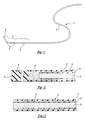
- Figure 1 is a perspective view of a guidewire for use with magnetic resonance systems, arranged according to an embodiment of the present invention;
- Figure 2 is a cross-sectional view of a portion of the guidewire of Figure 1, in a location near that indicated by arrow II;
- Figure 3 is a cross-sectional view of a portion of the guidewire of Figure 1, in a location near that indicated by arrow III;
- Figure 4 is a perspective view of a guidewire for use with magnetic resonance systems, arranged according to another embodiment of the present invention;
- Figures 5-7 are cross-sectional views of a portion of various guidewires arranged according to certain embodiments of the present invention;
- Figure 8 is a perspective view of a guidewire for use with magnetic resonance systems, arranged according to another embodiment of the present invention;
- Figure 9 is a cross-sectional view of a portion of the guidewire of Figure 8, in a location near that indicated by arrow IX;
- Figure 10 is a cross-sectional view of a portion of the guidewire of Figure 8, in a location near that indicated by arrow X; and
- Figures 11-13 are side elevation views of distal portions of guidewires arranged according to alternative embodiments of the present invention.
- The following description of the preferred embodiments of the present invention is merely illustrative in nature, and as such it does not limit in any way the present invention, its application, or uses. Numerous modifications may be made by those skilled in the art without departing from the true scope of the invention as defined by the accompanying claims.
- Referring to Figure 1, a perspective view of a guidewire according to a first preferred embodiment of the present invention is shown generally at 1. The
medical guidewire 1 is intended for use in intravascular medical procedures involving the use of magnetic resonance systems, including both magnetic resonance imaging and magnetic resonance tracking of the guidewire's position within the body of the patient. Guidewire 1 is constructed of abasic body 2 and adistal tip portion 3. The distal tip ofguidewire 1 includesseveral markers 4 embedded in thedistal tip portion 3, which are more visible under MR than the remainder of the guidewire. - The proximal portion of the
basic body 2 is illustrated in Figure 3, and incorporates a relatively long, thin core orglass body 5, which may be encased with aprotective coating 6 for improving the break strength of theglass body 5. Thecoated glass body 5 extends for substantially the length of the guidewire and is surrounded with apolymer sheath 7, which is adhered to theglass body 5 with aglue 8. -
Markers 4 are visible under MR because their magnetic susceptibility differs to a controlled extent from the remainder of the guidewire and surrounding body tissue, thus distorting the uniformity of the magnetic resonance field, and causing the magnetic field to become what is called "locally inhomogeneous." The material of themarkers 4 is selected specifically for this property, and acceptable materials include Dysprosium Oxide (Dy2O3). - The
glass body 5 is preferably made of a glass material having a high specific electric impedance, such as fiberglass, silica, or quartz. - The
coating 6 adds strength to theglass core 5, in that the coating allows theglass core 5 to be bent through a sharper turn or more tortuous path without breaking. Indeed, it has been found that the coatedglass core 5 may endure strain as high as 12%. A suitable material for thecoating 6 has been found to be polyimide. - The
outer polymer sheath 7 may be constructed from any of a variety of materials, including nylon. An additional advantage of the design of the present invention is that thepolymer sheath 7 can maintain the physical integrity of the guidewire, even if theglass core 5 should unexpectedly break. Of course, thepolymer sheath 7 may be provided with a lubricious or hydrophilic coating, as generally known in the art. - An intermediate portion of the guidewire is depicted in Figure 2, which focuses on a region near the transition at arrow II between the glass core proximal portion of the basic body, referred to as the "transition point."
- The
distal tip portion 3 of theguidewire 1 may be formed of a non-metallic material, such as plastic, as shown in Figure 2, or of a metal as shown in Figures 8-13. The outer diameter ofguidewire 1 preferably tapers to a smaller diameter toward the distal tip, as illustrated in Figures 8-13. The metal tip portion may be a material having a selected magnetic susceptibility, such as stainless steel or nickel titanium (nitinol). Preferably, the length of the metal distal tip segment is substantially shorter than the wavelength of the magnetic resonance field in which the guidewire is used. - A short metal collar (not shown) may be affixed to the guidewire at the transition point, to resist kinking and breakage of the
guidewire 1 at the transition point. - The
glue 8 is preferably of a type that cures upon exposure to ultraviolet light. Accordingly, thepolymer sheath 7 should be transparent, to allow theglue 8 to be exposed to the ultraviolet light after portions of theguidewire 1 are assembled as shown in Figures 1-3. - An alternative embodiment of the present invention is depicted in Figures 4-7, in which a
guidewire 11 has aproximal portion 12 and adistal tip portion 13.Guidewire 11 has aplastic sheath 16 in which a number of reinforcing fibers have been embedded.Sheath 16 may be shrunk around a bundle offibers 17, or thesheath 16 may be braided with the reinforcing fibers. Alternatively,fibers 18 may be embedded in apolymer matrix 19. In addition, a multiplicity of short reinforcingfibers 20 can be provided in apolymer matrix 21, surrounded by acoating 12. The reinforcing fibers may be of any suitable material, such as carbon, borium, aramide, or glass. - The guidewire of the present invention may also be constructed of more than one glass core body, all of which may be clad as a unit with a single protective coating.
- The distal tip of the guidewire may be bent slightly, to facilitate the selective steering of the guidewire along a desired vascular path.
- It should be understood that an unlimited number of configurations for the present invention can be realized. The foregoing discussion describes merely exemplary embodiments illustrating the principles of the present invention, the scope of which is recited in the following claims. Those skilled in the art will readily recognize from the description, claims, and drawings that numerous changes and modifications can be made without departing from the scope of the invention as defined by the accompanying claims.
Claims (13)
- A medical guidewire (1;11), for use in intravascular medical procedures and compatible with magnetic resonance, the guidewire having proximal and distal ends and comprising:a relatively long, thin core (5) extending for substantially the length of the guidewire, the core being made of a glass having a high specific electric impedance; anda polymer sheath (7,16) surrounding the core (5); characterised byat least one marker (4) positioned near a distal end of the guidewire, wherein the at least one marker (4) is visible under magnetic resonance due to susceptibility-induced magnetic field inhomogeneity, wherein:either the guidewire (1;11) is formed entirely of non-metallic materials with a high specific electrical impedance,or the guidewire (1;11) is formed entirely of non-metallic materials with a high specific electrical impedance, except for a relatively short distal tip segment (3;13) made of metal components affixed to the glass core (5) at a transition point, wherein the length of the relatively short distal tip segment (3;13) is shorter than the wavelength of a magnetic resonance field.
- The medical guidewire of Claim 1, which has said relatively short metal distal tip segment, wherein said tip segment (3;13) is made of nitinol.
- The medical guidewire of Claim 1 or Claim 2, which has said relatively short metal distal tip segment, wherein the polymer sheath (7;16) extends continuously from a location near the proximal end of the guidewire (1;11) to a location distal of the transition point, thus surrounding at least a portion of both the glass core (5) and the relatively short metal distal tip segment (3;13).
- The medical guidewire of any one of Claims 1 to 3, which has said relatively short metal distal tip segment (3;13), further comprising a short metal collar affixed to the guidewire (1;11) at the transition point, to resist kinking and breakage of the guidewire (1;11) at the transition point.
- The medical guidewire of any one of Claims 1 to 4, further comprising a plurality of reinforcing fibers (17;18;20) affixed to the core (5) and/or to the polymer sheath (7;16) to enhance the flexibility and torsion characteristics of the guidewire (1;11).
- The medical guidewire of Claim 5, wherein the material of the reinforcing fibers (17;18;20) is carbon, borium, aramide or glass.
- The medical guidewire of any one of Claims 1 to 6, wherein the material of the core (5) is fiberglass, silica or quartz.
- The medical guidewire of any one of Claims 1 to 7, wherein a distal segment of the glass core (5) tapers to a diameter at the distal end of the guidewire (1;11) that is smaller than the diameter of a major portion of the core.
- The medical guidewire of any one of Claims 1 to 8, wherein the material of the at least one marker (4) is Dysprosium Oxide (Dy2O3).
- The medical guidewire of any one of Claims 1 to 9, wherein the distal tip (3;13) of the guidewire (1;11) is bent slightly, to facilitate the selective steering of the guidewire (1;11) along a desired vascular path.
- The medical guidewire of any one of Claims 1 to 10, wherein the core (5) has a breaking strength, said core (5) being covered with a coating (6;12) for increasing said breaking strength.
- The medical guidewire of any one of Claims 1 to 11, wherein at least a portion of the polymer sheath (7;16) has a hydrophilic coating.
- The medical guidewire of any one of Claims 1 to 12, wherein the core (5) is formed of a plurality of glass core strands.
Applications Claiming Priority (3)
| Application Number | Priority Date | Filing Date | Title |
|---|---|---|---|
| NL1005662 | 1997-03-27 | ||
| NL1005662A NL1005662C2 (en) | 1997-03-27 | 1997-03-27 | Guide wire. |
| PCT/US1998/006080 WO1998042268A1 (en) | 1997-03-27 | 1998-03-27 | Glass core guidewire compatible with magnetic resonance |
Publications (3)
| Publication Number | Publication Date |
|---|---|
| EP1011491A1 EP1011491A1 (en) | 2000-06-28 |
| EP1011491A4 EP1011491A4 (en) | 2001-01-24 |
| EP1011491B1 true EP1011491B1 (en) | 2007-01-17 |
Family
ID=19764681
Family Applications (1)
| Application Number | Title | Priority Date | Filing Date |
|---|---|---|---|
| EP98913208A Expired - Lifetime EP1011491B1 (en) | 1997-03-27 | 1998-03-27 | Glass core guidewire compatible with magnetic resonance |
Country Status (5)
| Country | Link |
|---|---|
| EP (1) | EP1011491B1 (en) |
| AU (1) | AU6781698A (en) |
| DE (1) | DE69836912T2 (en) |
| NL (1) | NL1005662C2 (en) |
| WO (1) | WO1998042268A1 (en) |
Families Citing this family (8)
| Publication number | Priority date | Publication date | Assignee | Title |
|---|---|---|---|---|
| JP2001145699A (en) * | 1999-11-22 | 2001-05-29 | Nissho Corp | Guide wire |
| WO2001095794A1 (en) * | 2000-06-12 | 2001-12-20 | Cordis Corporation | Vascular guidewire for magnetic resonance and/or fluoroscopy |
| US6652507B2 (en) | 2001-07-03 | 2003-11-25 | Scimed Life Systems, Inc. | Intravascular catheter having multi-layered tip |
| DE102004028367A1 (en) | 2004-06-11 | 2005-12-29 | Biotronik Vi Patent Ag | Catheter Guidewire especially for cardio-vascular procedures |
| DE102008012743A1 (en) | 2008-03-05 | 2009-09-10 | Biotronik Vi Patent Ag | Catheter guidewire and method of making the same |
| DE102012214785A1 (en) * | 2012-08-20 | 2014-02-20 | Epflex Feinwerktechnik Gmbh | Medical guide wire with MR marker |
| JP6400586B2 (en) * | 2013-09-03 | 2018-10-03 | テルモ株式会社 | Guide wire |
| EP3717922A2 (en) | 2017-12-03 | 2020-10-07 | Cook Medical Technologies, LLC | Mri compatible interventional wireguide |
Family Cites Families (11)
| Publication number | Priority date | Publication date | Assignee | Title |
|---|---|---|---|---|
| US4739768B2 (en) * | 1986-06-02 | 1995-10-24 | Target Therapeutics Inc | Catheter for guide-wire tracking |
| US4832023A (en) * | 1987-06-03 | 1989-05-23 | Mcm Laboratories, Inc. | Method and apparatus for reducing blockage in body channels |
| US4867174A (en) * | 1987-11-18 | 1989-09-19 | Baxter Travenol Laboratories, Inc. | Guidewire for medical use |
| EP0436303A1 (en) * | 1989-12-01 | 1991-07-10 | C.R. Bard, Inc. | Guidewire with member for tracking along an indwelling device, and catheter exchange system |
| CA2068584C (en) * | 1991-06-18 | 1997-04-22 | Paul H. Burmeister | Intravascular guide wire and method for manufacture thereof |
| US5251640A (en) * | 1992-03-31 | 1993-10-12 | Cook, Incorporated | Composite wire guide shaft |
| US5217026A (en) * | 1992-04-06 | 1993-06-08 | Kingston Technologies, Inc. | Guidewires with lubricious surface and method of their production |
| US5439000A (en) * | 1992-11-18 | 1995-08-08 | Spectrascience, Inc. | Method of diagnosing tissue with guidewire |
| JP4408958B2 (en) * | 1995-02-28 | 2010-02-03 | ボストン サイエンティフィック コーポレーション | Medical instruments |
| NO962134L (en) * | 1995-05-26 | 1996-11-27 | Target Therapeutics Inc | Lining line of super elastic composite |
| US5690120A (en) * | 1996-05-24 | 1997-11-25 | Sarcos, Inc. | Hybrid catheter guide wire apparatus |
-
1997
- 1997-03-27 NL NL1005662A patent/NL1005662C2/en not_active IP Right Cessation
-
1998
- 1998-03-27 WO PCT/US1998/006080 patent/WO1998042268A1/en active IP Right Grant
- 1998-03-27 EP EP98913208A patent/EP1011491B1/en not_active Expired - Lifetime
- 1998-03-27 AU AU67816/98A patent/AU6781698A/en not_active Abandoned
- 1998-03-27 DE DE69836912T patent/DE69836912T2/en not_active Expired - Lifetime
Also Published As
| Publication number | Publication date |
|---|---|
| EP1011491A1 (en) | 2000-06-28 |
| EP1011491A4 (en) | 2001-01-24 |
| DE69836912T2 (en) | 2007-11-08 |
| AU6781698A (en) | 1998-10-20 |
| WO1998042268A1 (en) | 1998-10-01 |
| NL1005662C2 (en) | 1998-09-29 |
| DE69836912D1 (en) | 2007-03-08 |
Similar Documents
| Publication | Publication Date | Title |
|---|---|---|
| US6458088B1 (en) | Glass core guidewire compatible with magnetic resonance | |
| US20030208142A1 (en) | Vascular guidewire for magnetic resonance and /or fluoroscopy | |
| US6799067B2 (en) | MRI compatible guide wire | |
| JP5123119B2 (en) | Non-metallic guidewire | |
| CA2209178C (en) | Fiber tip guidewire | |
| EP0749334B1 (en) | Catheter guidewire with radiopaque markers | |
| JP5925145B2 (en) | Intravascular guidewire | |
| CA2195484C (en) | Stiff catheter guidewire with flexible distal portion | |
| EP0812599B1 (en) | Catheter guide wire | |
| EP0989820A1 (en) | Glass core guidewire compatible with magnetic resonance having reinforcing fibers | |
| EP3315163B1 (en) | Guidewires having improved mechanical strength and electromagnetic shielding | |
| WO2001095794A1 (en) | Vascular guidewire for magnetic resonance and/or fluoroscopy | |
| KR970069050A (en) | Compound Vascular Guide Wire | |
| EP1011491B1 (en) | Glass core guidewire compatible with magnetic resonance | |
| US20230310797A1 (en) | Multi-filar catheter body construction |
Legal Events
| Date | Code | Title | Description |
|---|---|---|---|
| PUAI | Public reference made under article 153(3) epc to a published international application that has entered the european phase |
Free format text: ORIGINAL CODE: 0009012 |
|
| 17P | Request for examination filed |
Effective date: 19991020 |
|
| AK | Designated contracting states |
Kind code of ref document: A1 Designated state(s): DE FR GB IE IT |
|
| A4 | Supplementary search report drawn up and despatched |
Effective date: 20001207 |
|
| AK | Designated contracting states |
Kind code of ref document: A4 Designated state(s): DE FR GB IE IT |
|
| RIC1 | Information provided on ipc code assigned before grant |
Free format text: 7A 61B 17/36 A, 7A 61M 25/01 B |
|
| 17Q | First examination report despatched |
Effective date: 20040219 |
|
| GRAP | Despatch of communication of intention to grant a patent |
Free format text: ORIGINAL CODE: EPIDOSNIGR1 |
|
| RIC1 | Information provided on ipc code assigned before grant |
Ipc: A61B 18/00 20060101AFI20060619BHEP |
|
| GRAS | Grant fee paid |
Free format text: ORIGINAL CODE: EPIDOSNIGR3 |
|
| GRAA | (expected) grant |
Free format text: ORIGINAL CODE: 0009210 |
|
| AK | Designated contracting states |
Kind code of ref document: B1 Designated state(s): DE FR GB IE IT |
|
| REG | Reference to a national code |
Ref country code: GB Ref legal event code: FG4D |
|
| REG | Reference to a national code |
Ref country code: IE Ref legal event code: FG4D |
|
| REF | Corresponds to: |
Ref document number: 69836912 Country of ref document: DE Date of ref document: 20070308 Kind code of ref document: P |
|
| ET | Fr: translation filed | ||
| PLBE | No opposition filed within time limit |
Free format text: ORIGINAL CODE: 0009261 |
|
| STAA | Information on the status of an ep patent application or granted ep patent |
Free format text: STATUS: NO OPPOSITION FILED WITHIN TIME LIMIT |
|
| 26N | No opposition filed |
Effective date: 20071018 |
|
| REG | Reference to a national code |
Ref country code: FR Ref legal event code: PLFP Year of fee payment: 19 |
|
| REG | Reference to a national code |
Ref country code: FR Ref legal event code: PLFP Year of fee payment: 20 |
|
| PGFP | Annual fee paid to national office [announced via postgrant information from national office to epo] |
Ref country code: FR Payment date: 20170327 Year of fee payment: 20 |
|
| PGFP | Annual fee paid to national office [announced via postgrant information from national office to epo] |
Ref country code: IE Payment date: 20170329 Year of fee payment: 20 Ref country code: GB Payment date: 20170327 Year of fee payment: 20 |
|
| PGFP | Annual fee paid to national office [announced via postgrant information from national office to epo] |
Ref country code: IT Payment date: 20170324 Year of fee payment: 20 |
|
| PGFP | Annual fee paid to national office [announced via postgrant information from national office to epo] |
Ref country code: DE Payment date: 20170329 Year of fee payment: 20 |
|
| REG | Reference to a national code |
Ref country code: DE Ref legal event code: R071 Ref document number: 69836912 Country of ref document: DE |
|
| REG | Reference to a national code |
Ref country code: GB Ref legal event code: PE20 Expiry date: 20180326 |
|
| PG25 | Lapsed in a contracting state [announced via postgrant information from national office to epo] |
Ref country code: GB Free format text: LAPSE BECAUSE OF EXPIRATION OF PROTECTION Effective date: 20180326 |
|
| REG | Reference to a national code |
Ref country code: IE Ref legal event code: MK9A |
|
| PG25 | Lapsed in a contracting state [announced via postgrant information from national office to epo] |
Ref country code: IE Free format text: LAPSE BECAUSE OF EXPIRATION OF PROTECTION Effective date: 20180327 |