EP1011012B1 - Method of and device for orientation of film cartridges in a canister using magnets - Google Patents
Method of and device for orientation of film cartridges in a canister using magnets Download PDFInfo
- Publication number
- EP1011012B1 EP1011012B1 EP99203911A EP99203911A EP1011012B1 EP 1011012 B1 EP1011012 B1 EP 1011012B1 EP 99203911 A EP99203911 A EP 99203911A EP 99203911 A EP99203911 A EP 99203911A EP 1011012 B1 EP1011012 B1 EP 1011012B1
- Authority
- EP
- European Patent Office
- Prior art keywords
- canister
- cartridge
- film
- magnet
- Prior art date
- Legal status (The legal status is an assumption and is not a legal conclusion. Google has not performed a legal analysis and makes no representation as to the accuracy of the status listed.)
- Expired - Lifetime
Links
- 238000000034 method Methods 0.000 title claims description 15
- 230000033001 locomotion Effects 0.000 claims description 6
- 230000001680 brushing effect Effects 0.000 claims 1
- 230000005291 magnetic effect Effects 0.000 description 6
- 238000004519 manufacturing process Methods 0.000 description 4
- 229910000831 Steel Inorganic materials 0.000 description 3
- 239000010959 steel Substances 0.000 description 3
- 230000000007 visual effect Effects 0.000 description 3
- 238000012986 modification Methods 0.000 description 2
- 230000004048 modification Effects 0.000 description 2
- 229910052761 rare earth metal Inorganic materials 0.000 description 2
- 150000002910 rare earth metals Chemical class 0.000 description 2
- 238000010276 construction Methods 0.000 description 1
- 239000002537 cosmetic Substances 0.000 description 1
- 238000004804 winding Methods 0.000 description 1
Images



Classifications
-
- G—PHYSICS
- G03—PHOTOGRAPHY; CINEMATOGRAPHY; ANALOGOUS TECHNIQUES USING WAVES OTHER THAN OPTICAL WAVES; ELECTROGRAPHY; HOLOGRAPHY
- G03B—APPARATUS OR ARRANGEMENTS FOR TAKING PHOTOGRAPHS OR FOR PROJECTING OR VIEWING THEM; APPARATUS OR ARRANGEMENTS EMPLOYING ANALOGOUS TECHNIQUES USING WAVES OTHER THAN OPTICAL WAVES; ACCESSORIES THEREFOR
- G03B17/00—Details of cameras or camera bodies; Accessories therefor
- G03B17/26—Holders for containing light sensitive material and adapted to be inserted within the camera
-
- Y—GENERAL TAGGING OF NEW TECHNOLOGICAL DEVELOPMENTS; GENERAL TAGGING OF CROSS-SECTIONAL TECHNOLOGIES SPANNING OVER SEVERAL SECTIONS OF THE IPC; TECHNICAL SUBJECTS COVERED BY FORMER USPC CROSS-REFERENCE ART COLLECTIONS [XRACs] AND DIGESTS
- Y10—TECHNICAL SUBJECTS COVERED BY FORMER USPC
- Y10T—TECHNICAL SUBJECTS COVERED BY FORMER US CLASSIFICATION
- Y10T29/00—Metal working
- Y10T29/49—Method of mechanical manufacture
- Y10T29/49826—Assembling or joining
-
- Y—GENERAL TAGGING OF NEW TECHNOLOGICAL DEVELOPMENTS; GENERAL TAGGING OF CROSS-SECTIONAL TECHNOLOGIES SPANNING OVER SEVERAL SECTIONS OF THE IPC; TECHNICAL SUBJECTS COVERED BY FORMER USPC CROSS-REFERENCE ART COLLECTIONS [XRACs] AND DIGESTS
- Y10—TECHNICAL SUBJECTS COVERED BY FORMER USPC
- Y10T—TECHNICAL SUBJECTS COVERED BY FORMER US CLASSIFICATION
- Y10T29/00—Metal working
- Y10T29/49—Method of mechanical manufacture
- Y10T29/49826—Assembling or joining
- Y10T29/49895—Associating parts by use of aligning means [e.g., use of a drift pin or a "fixture"]
Definitions
- the invention relates generally to the field of manufacturing, and in particular parts manufacturing and assembly.
- the inner (or exposed) disk is attached to the spool hub by three barbs and therefore rotates with the spool.
- the word EXPOSED may be printed on it, or to differentiate from the outer disk, it may be a different color.
- the outer (or unexposed) disk is attached to the crimp diameter of the end cap. It remains stationary relative to the cartridge.
- the word UNEXPOSED may be printed on it, or, again to differentiate from the inner disk, it may be a different color.
- U.S. Patent 5,708,879 shows a film cartridge with a visual exposure status indicator.
- US 5 669 205 A shows a device used in manufacturing film cartridges, wherein the cartridges with the film are inserted in their canisters
- US 5 406 346 A discloses to keep a film cartridge in a predetermined position inside a film cartridge chamber by means of magnets
- US 5 737 650 A discloses an exposed film indicator in a cartridge being magnetically operated
- US 5 645 240 A discloses an apparatus for inserting film into a film cartridge wherein the cartridge is rotated about its long axis.
- U.S. Patent 5,715,494 is another example of a film cartridge with a visual exposure status indicator.
- US 4 325 619 A discloses a miniature camera wherein rotary motions of shutter blades is obtained by magnetic forces
- US 5 552 849 A discloses another visual exposure indicating disk on a photographic film cartridge.
- the assembly process will accept the canned cartridges opened end up, either from a tray unloader or from a centrifugal feeder. Individual canisters will be singulated on the infeed conveyor, using a separator screw. They will then be loaded onto either a continuous motion rotary assembly turret, a dial indexer or some type of assembly chassis. Using this motion generated by the chassis, this process can be used to find the center of the spool and orient them all the same way so that the exposed film indicator can be applied.
- Each nest in the assembly device will contain a powerful rare earth magnet.
- a stationary belt device on the outer periphery of the device will contact the canister. Because the canister, which is in the nest, with the cartridge inside is rotating past and contacting a stationary belt, the frictional force developed between the canister and belt will cause the canister to rotate.
- the steel magazine, which is inside the canister, is not truly round, but has a flat section above the film exit slot. As the canister rotates, the flat section of the magazine will be attracted to the magnet with sufficient force that the cartridge will cease to rotate, even as the canister continues to rotate. Thus all the cartridges will be oriented consistently relative to the assembly tooling and the center of the spool will be in a known position.
- the exposed film indicator components will be applied with a straightline vertical motion with respect to the cartridge.
- the functionality of the exposed film indicator can be reversed by having the inner disk designated as unexposed and the outer disk designated as exposed and assembled to the cartridge in reverse order.
- Figure 1a shows a device 1 which rotates clockwise with twelve pockets 25. Also shown is the belt device 2 and the bearing housing 3. The pocket is defined in more detail in Figure 3. Attached to the shaft 4 below the bearing housing 3 (see Figure 1b), but not shown for clarity is a rotational drive device, such as a motor.
- the purpose of the belt device 2 is to provide a means to present a stationary, but flexible surface to the product 10, which will develop sufficient force to cause the product 10 to spin, but is compliant enough to not damage the product 10 and is able to follow the contour of the device and product assembly.
- the belt device 2 is attached to a common plate 5 through a series of long thin members 6 which act as leaf springs 6. This allows the belt device to have some compliance in the direction 7 as shown by the arrow.
- a conveyor would feed the product 10 into the device at position 8, and remove it from the device at position 9. The conveyor also is not shown for clarity.
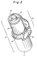
- FIG 2 is an enlarged view of the product assembly 10 which consists of a plastic canister 11 and a cartridge 12, such as a 35 mm film cartridge.
- the cartridge 12 is made up of a spool 13, preferably made of plastic, a steel shell, or magazine 15 and two steel end caps 14, which are staked onto the ends of the magazine 15.
- Protruding out of the cartridge 12 (preferably, approximately 58 mm) through the exit slot 18 in the flat section is the film leader 16.
- the film leader 16 tends to act as a leaf spring and pushes the cartridge 12 up against the inside wall of the canister 11 on the side opposite from where the film exits the cartridge. This phenomenon helps hold the cartridge 12 in one place relative to the inside of the canister 11. Note that the cartridge 12 is free to move anywhere within the confines of the canister 11.
- FIG 3 is an enlarged view of the area where the device 1, containing twelve pockets 25, the belt device 2, and product 10, come together.
- the pocket 25 is a means to capture the product assembly.
- Each pocket contains a magnet 23 and a machined surface 24, opposed to the magnet 23 and a floor for the product to sit on. It is important that these two surfaces are approximately 90° apart so that they form and act as a "V" Block. The rest of the surfaces in each pocket 25 are used to help guide the product 10 into the pocket 25.
- the product 10 is shown as it would be inserted randomly into the pocket 25 on the device 1. As the device 1 rotates in a clockwise direction towards position 9 the canister 11 will come in contact with a stationary belt device 2.
- the canister is captured between the belt device 2, the magnet 23 and the machined surface 24 on the pockets 25.
- the canister 11 is trapped between the belt device 2 and the pocket 25 on the moving device 1, and therefore can not move laterally.
- the canister 11 contained in the pocket 25 and being dragged across the belt device 2 will begin to rotate (similar to a wheel being dragged across a surface).
- the film leader 16 acts as a leaf spring, and develops enough force to hold the cartridge 12 in place relative to the canister 11, the cartridge 12 also rotates with the canister 11.
- the canister 11 rotates in the opposite direction. Once the flat section of the magazine 15 rotates to a position in proximity to the magnet 23, the magnetic force attracts this flat section.
- the force generated by the magnet 23 is larger than the force generated by the leaf spring action caused by the leader. Therefore the cartridge 12 will slop rotating and the flat section with stay aligned with the magnet 23. The canister 11 will then continue to rotate until the pocket 25 containing the product assembly 10 reaches the end of the belt device 2. At this point, there is no longer a force being applied to the canister 11 to cause it to rotate, hence the canister 11 will stop rotating. The cartridge 12 however, will remain stationary with the flat section aligned with the magnet 23. The canister 11, with the cartridge 12 in a known rotational orientation and position, can continue to travel with the device 1 to downstream assembly operations as warranted.
- the center of the spool can be located consistently for assembly of the exposed film indicator while it is in the canister, and the orientation of the cartridge relative to the device is adjusted to a consistent position.
Landscapes
- Physics & Mathematics (AREA)
- General Physics & Mathematics (AREA)
- Replacement Of Web Rolls (AREA)
- Photographic Developing Apparatuses (AREA)
Description
- The invention relates generally to the field of manufacturing, and in particular parts manufacturing and assembly.
- What is needed in the art is a film cartridge which will indicate whether the film in the cartridge has been exposed.
- Recently there has been a desire by snap-shooters, photo enthusiasts, and professionals to be able to determine if a roll of film has been advanced through a camera or has never been used. This can be accomplished by attaching an exposed film indicator to the long end of the spool on a 35mm cartridge. This is primarily needed when shooting multiple rolls of film, or for the purpose of some consumer and professional cameras, when a roll is only partially exposed to be used again later.
- One problem involving assembling the exposed film indicator to the cartridge, is developing a method to reliably attach two thin disks to the long hub end of the spool. The inner (or exposed) disk is attached to the spool hub by three barbs and therefore rotates with the spool. The word EXPOSED may be printed on it, or to differentiate from the outer disk, it may be a different color. The outer (or unexposed) disk is attached to the crimp diameter of the end cap. It remains stationary relative to the cartridge. The word UNEXPOSED may be printed on it, or, again to differentiate from the inner disk, it may be a different color. When a customer purchases a fresh roll of film, the outer disk will be visible. As film is wound back into the cartridge after the pictures are taken, a tab that sticks up on the inner disk engages a tab that sticks down on the outer disk. The inner disk then exits through a slot in the outer disk and is visible to the customer.
- U.S. Patent 5,708,879 shows a film cartridge with a visual exposure status indicator.
- US 5 669 205 A shows a device used in manufacturing film cartridges, wherein the cartridges with the film are inserted in their canisters, US 5 406 346 A discloses to keep a film cartridge in a predetermined position inside a film cartridge chamber by means of magnets, US 5 737 650 A discloses an exposed film indicator in a cartridge being magnetically operated, US 5 645 240 A discloses an apparatus for inserting film into a film cartridge wherein the cartridge is rotated about its long axis.
- U.S. Patent 5,715,494 is another example of a film cartridge with a visual exposure status indicator.
- US 4 325 619 A discloses a miniature camera wherein rotary motions of shutter blades is obtained by magnetic forces, US 5 552 849 A discloses another visual exposure indicating disk on a photographic film cartridge.
- To implement adding exposure indication to a 35 mm film cartridge in a timely and cost effective manner, it is necessary to minimize the impact on the existing manufacturing infrastructure. Given the complexity of this infrastructure and the space constraints around the equipment, it is highly desirable to add the feature after the film cartridge is completely assembled. Since the completed film cartridge is loaded into the canister at the end of the film winding operation, the feature must be assembled to the cartridge either by removing the cartridge from the canister or while the cartridge is in the canister. It is advantageous to assemble the feature to the film cartridge while it is in the canister since:
- 1) The canister provides a convenient method of conveying and singulating the film cartridges for the assembly operations.
- 2) It is difficult to reinsert the film cartridge back into the canister without using a special motion to wrap the film leader around the cartridge.
- 3) Reduced handling of the cartridges and thus the potential for cosmetic damage to either the cartridge or the film leader is reduced.
- 4) Equipment space limitations does not permit cartridge removal.
-
- The above problem of applying an exposed film indicator to the cartridge after assembly of the cartridge is solved by the method of one of the claims 1 to 8 or by the apparatus according to one of the
claims 9 to 10. - The assembly process will accept the canned cartridges opened end up, either from a tray unloader or from a centrifugal feeder. Individual canisters will be singulated on the infeed conveyor, using a separator screw. They will then be loaded onto either a continuous motion rotary assembly turret, a dial indexer or some type of assembly chassis. Using this motion generated by the chassis, this process can be used to find the center of the spool and orient them all the same way so that the exposed film indicator can be applied.
- Each nest in the assembly device will contain a powerful rare earth magnet. A stationary belt device on the outer periphery of the device will contact the canister. Because the canister, which is in the nest, with the cartridge inside is rotating past and contacting a stationary belt, the frictional force developed between the canister and belt will cause the canister to rotate. The steel magazine, which is inside the canister, is not truly round, but has a flat section above the film exit slot. As the canister rotates, the flat section of the magazine will be attracted to the magnet with sufficient force that the cartridge will cease to rotate, even as the canister continues to rotate. Thus all the cartridges will be oriented consistently relative to the assembly tooling and the center of the spool will be in a known position.
- Once the center of the spool has been found, the exposed film indicator components will be applied with a straightline vertical motion with respect to the cartridge.
- It is noted, that if desired the functionality of the exposed film indicator can be reversed by having the inner disk designated as unexposed and the outer disk designated as exposed and assembled to the cartridge in reverse order.
- The foregoing and other objectives, features, and advantages of the invention will be apparent from the following more particular description, including the presently preferred embodiments of the invention, as illustrated in the accompanying drawings in which:
- Figures 1a and b show overall top and side views of the magnetic orienting device.
- Figure 2 is an exploded view of the product, typically a 35mm film cartridge and a canister.
- Figure 3 is an enlarged view of the magnetic orienting device, showing the area where the device, product and belt interface.
-
- Figure 1a shows a device 1 which rotates clockwise with twelve
pockets 25. Also shown is thebelt device 2 and the bearinghousing 3. The pocket is defined in more detail in Figure 3. Attached to the shaft 4 below the bearing housing 3 (see Figure 1b), but not shown for clarity is a rotational drive device, such as a motor. The purpose of thebelt device 2 is to provide a means to present a stationary, but flexible surface to theproduct 10, which will develop sufficient force to cause theproduct 10 to spin, but is compliant enough to not damage theproduct 10 and is able to follow the contour of the device and product assembly. Thebelt device 2 is attached to acommon plate 5 through a series of long thin members 6 which act as leaf springs 6. This allows the belt device to have some compliance in thedirection 7 as shown by the arrow. Typically a conveyor would feed theproduct 10 into the device atposition 8, and remove it from the device atposition 9. The conveyor also is not shown for clarity. - Figure 2 is an enlarged view of the
product assembly 10 which consists of a plastic canister 11 and acartridge 12, such as a 35 mm film cartridge. Thecartridge 12 is made up of aspool 13, preferably made of plastic, a steel shell, ormagazine 15 and twosteel end caps 14, which are staked onto the ends of themagazine 15. There is a flat section on themagazine 15 where the film exits 18 thecartridge 12 Protruding out of the cartridge 12 (preferably, approximately 58 mm) through the exit slot 18 in the flat section is thefilm leader 16. Thefilm leader 16 tends to act as a leaf spring and pushes thecartridge 12 up against the inside wall of the canister 11 on the side opposite from where the film exits the cartridge. This phenomenon helps hold thecartridge 12 in one place relative to the inside of the canister 11. Note that thecartridge 12 is free to move anywhere within the confines of the canister 11. - Figure 3 is an enlarged view of the area where the device 1, containing twelve
pockets 25, thebelt device 2, andproduct 10, come together. Thepocket 25 is a means to capture the product assembly. Each pocket contains amagnet 23 and amachined surface 24, opposed to themagnet 23 and a floor for the product to sit on. It is important that these two surfaces are approximately 90° apart so that they form and act as a "V" Block. The rest of the surfaces in eachpocket 25 are used to help guide theproduct 10 into thepocket 25. Atposition 8, theproduct 10 is shown as it would be inserted randomly into thepocket 25 on the device 1. As the device 1 rotates in a clockwise direction towardsposition 9 the canister 11 will come in contact with astationary belt device 2. At this point the canister is captured between thebelt device 2, themagnet 23 and the machinedsurface 24 on thepockets 25. The canister 11 is trapped between thebelt device 2 and thepocket 25 on the moving device 1, and therefore can not move laterally. The canister 11 contained in thepocket 25 and being dragged across thebelt device 2 will begin to rotate (similar to a wheel being dragged across a surface). As previously stated, because thefilm leader 16 acts as a leaf spring, and develops enough force to hold thecartridge 12 in place relative to the canister 11, thecartridge 12 also rotates with the canister 11. As the device 1 continues to rotate, the canister 11 rotates in the opposite direction. Once the flat section of themagazine 15 rotates to a position in proximity to themagnet 23, the magnetic force attracts this flat section. By using a rare earth magnet, which generates a strong magnetic force field, the force generated by themagnet 23 is larger than the force generated by the leaf spring action caused by the leader. Therefore thecartridge 12 will slop rotating and the flat section with stay aligned with themagnet 23. The canister 11 will then continue to rotate until thepocket 25 containing theproduct assembly 10 reaches the end of thebelt device 2. At this point, there is no longer a force being applied to the canister 11 to cause it to rotate, hence the canister 11 will stop rotating. Thecartridge 12 however, will remain stationary with the flat section aligned with themagnet 23. The canister 11, with thecartridge 12 in a known rotational orientation and position, can continue to travel with the device 1 to downstream assembly operations as warranted. - Thus using magnetics, the center of the spool can be located consistently for assembly of the exposed film indicator while it is in the canister, and the orientation of the cartridge relative to the device is adjusted to a consistent position.
- The many features and advantages of the invention are apparent from the detailed specification and thus it is intended by the appended claims to cover all such features and advantages which fall within the scope of the invention as claimed. Further, since numerous modifications and changes will readily occur to those skilled in the art, it is not desired to limit the invention to the exact construction and operation illustrated and described, and accordingly all suitable modifications and equivalents may be resorted to, falling within the scope of the invention as defined by the appended claims.
Claims (10)
- A method of assembling an exposed film indicator to a film cartridge (12) after film has been placed in said cartridge (12), containing a spool, (13) said cartridge (12) being in a canister (11) in a nest, the method comprising the steps of:a) placing the canister (18) containing a said cartridge (12) in a pocket (25) located at the periphery of a device (1), said pocket having a magnet (23) and a machined surface (24) attached thereto, and rotating the device (1) clockwise;b) positioning a non-rotating belt device (2) on a portion of a circumference of said device (1);c) rotating the device (1) so that the canister (11) contained in the pocket (25) on the device (1) brushes against the belt device (2), causing it to rotate;d) continuing to rotate the device (1) clockwise so that the cartridges (12) is held in place relative to the canister (11) and the canister (11) rotates counterclockwise; ande) continuing to rotate the device (1) until the canister (11) reaches a position (9) away from the belt device (2) and the canister (11) stops rotating whereby the cartridge (12) is oriented in a predetermined angular position by means of the attraction of a portion of said cartridge (12) by said magnet (23).
- The method of claim 1 wherein the film is a 35 mm cartridge (18) with a protruding film leader (16).
- The method of claim 1 wherein the magnet (23) and machined surfaces (24) form a V-shape and are approximately 90° apart.
- The method of claim 1 wherein the device (1) contains a plurality of pockets (25) with a plurality of magnets (23) and machined surfaces (24).
- The method of claim 1 wherein the belt device (2) contacts the canister (11).
- The method of claim 1 wherein the device (1) is a continuous motion rotary turret.
- The method of claim 1 wherein the device (1) is a dial indexer.
- The method of claim 1 wherein the device (1) is an assembly chassis.
- An apparatus for orienting a film cartridge (12) in a canister (11) to a predetermined angular position comprising:a) a device (1) containing at least one pocket (25) at its periphery each pocket (25) containing a magnet (23) and machined surfaces (24); andb) a belt device (2) which is capable of brushing against said canister (11) while said device is rotating clockwise and subsequently releases said canister (11) which is located in said pocket (25) on said device (1) arranged such that a portion of said cartridge (12) is attracted by said magnet (23) and thereby maintained in said predetermined angular position.
- The apparatus of claim 9 wherein said magnets (23) and said machined surfaces (24) form a V-shape which are approximately 90° apart.
Applications Claiming Priority (2)
| Application Number | Priority Date | Filing Date | Title |
|---|---|---|---|
| US212455 | 1998-12-16 | ||
| US09/212,455 US6113287A (en) | 1998-12-16 | 1998-12-16 | Magnetic orientation process and device |
Publications (2)
| Publication Number | Publication Date |
|---|---|
| EP1011012A1 EP1011012A1 (en) | 2000-06-21 |
| EP1011012B1 true EP1011012B1 (en) | 2002-01-16 |
Family
ID=22791095
Family Applications (1)
| Application Number | Title | Priority Date | Filing Date |
|---|---|---|---|
| EP99203911A Expired - Lifetime EP1011012B1 (en) | 1998-12-16 | 1999-11-22 | Method of and device for orientation of film cartridges in a canister using magnets |
Country Status (3)
| Country | Link |
|---|---|
| US (1) | US6113287A (en) |
| EP (1) | EP1011012B1 (en) |
| DE (1) | DE69900669T2 (en) |
Families Citing this family (11)
| Publication number | Priority date | Publication date | Assignee | Title |
|---|---|---|---|---|
| US6605751B1 (en) | 1997-11-14 | 2003-08-12 | Acrymed | Silver-containing compositions, devices and methods for making |
| US8679523B2 (en) | 1999-12-30 | 2014-03-25 | Kimberly-Clark Worldwide, Inc. | Oxygen-delivery closed cell foam matrix for wound treatment |
| US8486426B2 (en) | 2002-07-29 | 2013-07-16 | Kimberly-Clark Worldwide, Inc. | Methods and compositions for treatment of dermal conditions |
| BRPI0513967A (en) | 2004-07-30 | 2008-05-20 | Acrymed Inc | antimicrobial silver compositions |
| EP1781098B1 (en) | 2004-07-30 | 2015-10-07 | Avent, Inc. | Antimicrobial devices and compositions |
| US8361553B2 (en) | 2004-07-30 | 2013-01-29 | Kimberly-Clark Worldwide, Inc. | Methods and compositions for metal nanoparticle treated surfaces |
| US9289378B2 (en) | 2004-09-20 | 2016-03-22 | Avent, Inc. | Antimicrobial amorphous compositions |
| EP2015722B1 (en) | 2006-04-28 | 2016-11-16 | Avent, Inc. | Antimicrobial site dressings |
| GB2492111B (en) * | 2011-06-22 | 2015-04-08 | Ortery Technologies Inc | Photography studio with turntable driving mechanism |
| US8925853B2 (en) * | 2012-08-27 | 2015-01-06 | The Procter & Gamble Company | Mandrel cupping assembly |
| RU2565851C1 (en) * | 2014-08-01 | 2015-10-20 | Сергей Вячеславович Аксёнов | Modular apparatus for circular photographic and video recording |
Family Cites Families (11)
| Publication number | Priority date | Publication date | Assignee | Title |
|---|---|---|---|---|
| US4325619A (en) * | 1980-11-07 | 1982-04-20 | Wrist-A-Matic, Ltd. | Camera |
| US5406346A (en) * | 1992-04-20 | 1995-04-11 | Asahi Kogaku Kogyo Kabushiki Kaisha | Adaptor for film cartridge |
| US5953806A (en) * | 1994-05-23 | 1999-09-21 | Fuji Photo Film Co., Ltd. | Apparatus and method of loading lens-fitted photo film unit with photo film |
| JPH07311443A (en) * | 1994-05-17 | 1995-11-28 | Fuji Photo Film Co Ltd | Method and device for assembling photographic film cartridge |
| US5552849A (en) * | 1995-01-23 | 1996-09-03 | Eastman Kodak Company | Visual exposure indicating system |
| IT1282152B1 (en) * | 1995-04-28 | 1998-03-16 | Systel International Spa | APPARATUS TO INSERT THE FILM INSIDE A LOADER |
| GB9512650D0 (en) * | 1995-06-21 | 1995-08-23 | Kodak Ltd | Packing of photographic film |
| JP3519845B2 (en) * | 1995-06-23 | 2004-04-19 | 富士写真フイルム株式会社 | Photo film winding method and apparatus |
| US5715494A (en) * | 1996-04-03 | 1998-02-03 | Eastman Kodak Company | Film cartridge with film-exposed visual indicator |
| US5737650A (en) * | 1996-12-16 | 1998-04-07 | Eastman Kodak Company | Photographic medium cartridge with magnetically activated status indicator |
| US5708879A (en) * | 1997-01-10 | 1998-01-13 | Eastman Kodak Company | Film cartridge with visual exposure status indicator |
-
1998
- 1998-12-16 US US09/212,455 patent/US6113287A/en not_active Expired - Fee Related
-
1999
- 1999-11-22 DE DE69900669T patent/DE69900669T2/en not_active Expired - Fee Related
- 1999-11-22 EP EP99203911A patent/EP1011012B1/en not_active Expired - Lifetime
Also Published As
| Publication number | Publication date |
|---|---|
| DE69900669T2 (en) | 2002-08-22 |
| DE69900669D1 (en) | 2002-02-21 |
| EP1011012A1 (en) | 2000-06-21 |
| US6113287A (en) | 2000-09-05 |
Similar Documents
| Publication | Publication Date | Title |
|---|---|---|
| US6113287A (en) | Magnetic orientation process and device | |
| US4194822A (en) | Photographic film cartridge assembly and camera | |
| CA1313079C (en) | Film cassette | |
| US4608617A (en) | Magnetic recording disk cartridge | |
| US4972649A (en) | Photographic film package and method of making the same | |
| US4884087A (en) | Photographic film package and method of making the same | |
| US4620255A (en) | Tape cartridge static eliminator | |
| US4688127A (en) | Magnetic recording disk cartridge with locking member | |
| US5363156A (en) | Film cartridge projection device | |
| CA1117346A (en) | Automatic film retriever | |
| US4826097A (en) | Reel spindle apparatus with internal clamping member | |
| US3512734A (en) | Tape cartridge | |
| JPH095947A (en) | Method and apparatus for insertion of cartridge of wound photographic film into container | |
| US4488191A (en) | Magnetic recording disk cartridge | |
| US3779484A (en) | Film magazine with drive capstan | |
| US6171000B1 (en) | Gimbaled roller assembly process and device | |
| EP1011013B1 (en) | Conical centering process and device for a film cartridge in a packaging canister | |
| US5701663A (en) | Apparatus for assembling photographic film cassette | |
| US6254023B1 (en) | Photo film cassette | |
| US5493352A (en) | Film cartridge magazine | |
| US6763184B2 (en) | Film assembly | |
| EP1122591A1 (en) | Camera | |
| EP1310956A2 (en) | Wide tape holding frame | |
| US5555067A (en) | Photographic film separating device and separation method | |
| EP1041430A1 (en) | Film cassette having loosely-retained, reversibly separable memory module, and photographic apparatus |
Legal Events
| Date | Code | Title | Description |
|---|---|---|---|
| PUAI | Public reference made under article 153(3) epc to a published international application that has entered the european phase |
Free format text: ORIGINAL CODE: 0009012 |
|
| AK | Designated contracting states |
Kind code of ref document: A1 Designated state(s): DE FR GB |
|
| AX | Request for extension of the european patent |
Free format text: AL;LT;LV;MK;RO;SI |
|
| 17P | Request for examination filed |
Effective date: 20001116 |
|
| GRAG | Despatch of communication of intention to grant |
Free format text: ORIGINAL CODE: EPIDOS AGRA |
|
| AKX | Designation fees paid |
Free format text: DE FR GB |
|
| 17Q | First examination report despatched |
Effective date: 20010221 |
|
| GRAG | Despatch of communication of intention to grant |
Free format text: ORIGINAL CODE: EPIDOS AGRA |
|
| GRAH | Despatch of communication of intention to grant a patent |
Free format text: ORIGINAL CODE: EPIDOS IGRA |
|
| GRAH | Despatch of communication of intention to grant a patent |
Free format text: ORIGINAL CODE: EPIDOS IGRA |
|
| GRAA | (expected) grant |
Free format text: ORIGINAL CODE: 0009210 |
|
| REG | Reference to a national code |
Ref country code: GB Ref legal event code: IF02 |
|
| AK | Designated contracting states |
Kind code of ref document: B1 Designated state(s): DE FR GB |
|
| REF | Corresponds to: |
Ref document number: 69900669 Country of ref document: DE Date of ref document: 20020221 |
|
| ET | Fr: translation filed | ||
| PLBE | No opposition filed within time limit |
Free format text: ORIGINAL CODE: 0009261 |
|
| STAA | Information on the status of an ep patent application or granted ep patent |
Free format text: STATUS: NO OPPOSITION FILED WITHIN TIME LIMIT |
|
| 26N | No opposition filed | ||
| PGFP | Annual fee paid to national office [announced via postgrant information from national office to epo] |
Ref country code: FR Payment date: 20031105 Year of fee payment: 5 |
|
| PGFP | Annual fee paid to national office [announced via postgrant information from national office to epo] |
Ref country code: DE Payment date: 20031128 Year of fee payment: 5 |
|
| PGFP | Annual fee paid to national office [announced via postgrant information from national office to epo] |
Ref country code: GB Payment date: 20041004 Year of fee payment: 6 |
|
| PG25 | Lapsed in a contracting state [announced via postgrant information from national office to epo] |
Ref country code: DE Free format text: LAPSE BECAUSE OF NON-PAYMENT OF DUE FEES Effective date: 20050601 |
|
| PG25 | Lapsed in a contracting state [announced via postgrant information from national office to epo] |
Ref country code: FR Free format text: LAPSE BECAUSE OF NON-PAYMENT OF DUE FEES Effective date: 20050729 |
|
| REG | Reference to a national code |
Ref country code: FR Ref legal event code: ST |
|
| PG25 | Lapsed in a contracting state [announced via postgrant information from national office to epo] |
Ref country code: GB Free format text: LAPSE BECAUSE OF NON-PAYMENT OF DUE FEES Effective date: 20051122 |
|
| GBPC | Gb: european patent ceased through non-payment of renewal fee |
Effective date: 20051122 |