EP1010975A1 - Capteur optique pour la mesure de la concentration de liquides - Google Patents
Capteur optique pour la mesure de la concentration de liquides Download PDFInfo
- Publication number
- EP1010975A1 EP1010975A1 EP99309514A EP99309514A EP1010975A1 EP 1010975 A1 EP1010975 A1 EP 1010975A1 EP 99309514 A EP99309514 A EP 99309514A EP 99309514 A EP99309514 A EP 99309514A EP 1010975 A1 EP1010975 A1 EP 1010975A1
- Authority
- EP
- European Patent Office
- Prior art keywords
- fluid
- ink
- light
- optical
- concentration
- Prior art date
- Legal status (The legal status is an assumption and is not a legal conclusion. Google has not performed a legal analysis and makes no representation as to the accuracy of the status listed.)
- Withdrawn
Links
Images
Classifications
-
- B—PERFORMING OPERATIONS; TRANSPORTING
- B41—PRINTING; LINING MACHINES; TYPEWRITERS; STAMPS
- B41J—TYPEWRITERS; SELECTIVE PRINTING MECHANISMS, i.e. MECHANISMS PRINTING OTHERWISE THAN FROM A FORME; CORRECTION OF TYPOGRAPHICAL ERRORS
- B41J2/00—Typewriters or selective printing mechanisms characterised by the printing or marking process for which they are designed
- B41J2/005—Typewriters or selective printing mechanisms characterised by the printing or marking process for which they are designed characterised by bringing liquid or particles selectively into contact with a printing material
- B41J2/01—Ink jet
- B41J2/17—Ink jet characterised by ink handling
- B41J2/195—Ink jet characterised by ink handling for monitoring ink quality
-
- G—PHYSICS
- G01—MEASURING; TESTING
- G01N—INVESTIGATING OR ANALYSING MATERIALS BY DETERMINING THEIR CHEMICAL OR PHYSICAL PROPERTIES
- G01N21/00—Investigating or analysing materials by the use of optical means, i.e. using sub-millimetre waves, infrared, visible or ultraviolet light
- G01N21/17—Systems in which incident light is modified in accordance with the properties of the material investigated
- G01N21/59—Transmissivity
Definitions
- the present invention relates to optical concentration sensing devices and, more particularly, to measurement of ink concentration for control in jet fluid systems.
- the ink used which includes a carrier fluid, such as water or a solvent, and dye, is continuously recirculated through the system. As it is recirculated, it mixes with air in the return lines and is maintained under vacuum in the ink reservoir. Evaporation of the carrier fluid due to the air-ink interaction increases the dye concentration of the ink which changes various fluid properties such as viscosity and surface tension. Therefore the optimal parameters used to control the ink jet printing process change as the ink concentration varies. As would be obvious to one skilled in the art, affecting ink properties such as viscosity is detrimental, since the energy required to stimulate filaments is determined partially by the viscosity of the fluid.
- Proper dye concentration is essential to the stable operation of an ink jet print head.
- the measurement of dye concentration is used to determine the amount of replenisher needed to mix with the ink to compensate for the carrier fluid lost due to evaporation.
- the ink usage rate due to printing is much higher than loss rate due to evaporation, therefore the fluid system can be refilled with ink without significantly affecting the ink concentration.
- the system when little or no printing is being done, the system is in an idle condition and the evaporation rate of the carrier fluid is typically higher than the amount of ink removed during printing. In this instance, then, the ink concentration level increases. A replenishment fluid is needed to bring the ink concentration level down to the proper mixture.
- Maintaining ink concentration in a continuous ink jet printing system is known in the art.
- One prior art method for controlling the ink concentration involves counting the print drops. By knowing the number of drops printed and the typical drop size, derived from hole size, one has a measure of the amount of ink printed; the actuations of the float in the tank are used to determine the volume of fluid lost from the tank; the difference between the amount of fluid lost from the tank and the amount printed is assumed to be vehicle lost due to evaporation.
- Counting printed drops is open loop control with no feedback parameters. This scheme is sensitive to the accuracy of the estimated drop volume. Small holes size errors or pressure variations can produce drop volumes larger or small than assumed by the control system. Ink losses due to spillage or leakage can also not be accounted for. As a result, this scheme cannot maintain the ink concentration required for high print quality applications.
- Ink concentration has also been monitored by means of the resistivity if the ink, as in patent U.S. Patent No. 3,761,953 and European Patent No. 0597628A.
- Resistivity control also is not precise.
- the resistivity of the ink is not only affected by the ionic content of the dye but also by ions from impurities in the dye stuff and the ink vehicle. Temperature also affects resistivity and calibration curves are necessary to correlate the concentration and resistivity at various temperatures.
- the resistivity of the ink also changes with time after the ink has been initially installed in the system. As a result, resistivity is less than an ideal indicator of ink concentration.
- the width of the cell must be fairly large.
- the resulting large surface area of the optical plates makes the spacing of the optical plates sensitive to changes in ink pressure. As the absorption of the light in the cell varies exponentially with the spacing, the apparent concentration of the ink, as indicated by the optical absorption in the optical cell, varies with ink pressure.
- the optical concentration sensor described in U.S. Patent No. 5,241,189 uses an infrared light emitting diode. Not all dyes and pigment used in inks are absorbing in the IR. As a result, the ⁇ 189 patent is not applicable for use with all inks. Even with a visible light spectrum, different inks, especially different color inks, have wildly different light absorption characteristics. To provide the desired ink concentration sensitivity for the different inks, one would need to use optical cells whose thickness must be matched to the ink of choice. This is not a practical option.
- an ink concentration sensor which can be used effectively with a broad range of inks without the need to be specially tuned for each selected ink. Furthermore, the sensor should not be sensitive to the ink pressure nor should it produce excessive pressure drops.
- the electrical output of the sensor is directly proportional to the concentration.
- an improved optical concentration sensor for use with continuous ink jet printers.
- the optical concentration sensor has an optical cell which can contain a fluid to be tested, at least one light source for passing light through the fluid, at least one light detector for detecting light transmitted through the fluid, and electronics for monitoring a first output from the light detector and providing a second output related to concentration of the fluid.
- the improvement comprises curved inner surfaces of the optical cell walls for producing at least one region with a narrow gap for transmission of light through the fluid and regions with wider gaps for more efficient flow of fluid through the cell.
- the optical concentration sensor of the present invention provides an electrical voltage output directly proportional to the concentration of the ink flowing through it, regardless of color.
- the thin fluid channel required to make the optical transmission measurements produced excessive pressure drops in the fluid system.
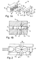
- This problem is eliminated in the present invention by replacing the flat glass plate walls of the optical cell with curved walls. As shown in Fig. 2, closely spaced curved glass walls provide the desired small gap for transmitting light through the ink. Because of the curvature of the glass walls, the narrow gap quickly widens out. As a result, the pressure drop of the ink flowing through the channel is greatly reduced.
- the light can be focused down through the narrow gap region of the optical cell and onto the photodetector. In this way, the optical sensor can more efficiently use the light from the light source.
- two glass rods 12 in plane with each other form the optical path with the gap G between them for the ink to be tested.
- the rods are sloped with respect to each other to provide different thicknesses of ink fluid for each light path.
- the gap at the end G W can be different from the gap at the end G N , illustrated in Fig. 1A, with G W , for example, being 0.0012" and G N , by contrast being 0.006 inches.
- the ideal optical concentration sensor of the present invention is a universal device that can be used on multiple inks ranging from black to color, and provides voltage output directly proportional to the ink concentration.
- Inks absorb different frequencies of light depending upon their color. For instance, cyan ink absorbs yellow light, magenta absorbs green light, and yellow ink absorbs blue light. Black ink, of course, absorbs nearly all colors.
- the wavelengths of light which are most strongly absorbed by that ink must be monitored.
- the absorption rate intensity of an ink at such wavelengths strongly absorbed by an ink will change as the ink concentration changes.
- light will always pass through that ink at the same level no matter what the concentration.
- Light at these not absorbed wavelengths will produce a high background output from the photodetector, lowering the sensitivity of the system to changes in ink concentration.
- only light with wavelengths that are highly absorbed by the ink should be used in the optical concentration sensor.
- the optical concentration sensor according to the present invention is equipped with four sources of light: red, amber, green, and blue LEDs. If cyan ink concentration is being monitored, the amber LED is employed; if magenta, the green; and if yellow, the blue. For black ink, a red LED is used, although other color sources would also be acceptable. It has been found that LED's (notably orange and yellow) emit infrared light in addition to their visible light. To prevent this undesired IR emission from being detected, suitable suppression means, such as KG5 Schott glass filters, may be used in the optical path. These filters give optimum suppression of the IR while being quite transparent in the visible.
- color gelatin filters are employed for the green and blue light paths to narrow the band of frequencies which reach the detectors to those that are most readily absorbed by the magenta and yellow inks, respectively.
- the intent is to enhance the sensitivity to changes in concentration for these inks.
- a white light with appropriate filters or in combination with spectrally sensitive detectors.
- a white light could be used in combination with a prism or diffraction grating to spread out the spectrum. It would then be possible to utilize an array detector such as a CCD, or other means to detect the transmitted light in the spectral range of interest.
- an array detector such as a CCD, or other means to detect the transmitted light in the spectral range of interest.
- Light passes from LED 22 through the first rod 12a.
- a minimal gap 24 between the rods 12 varies from approximately 1.2 mils to 6 mils over the length of the rods, for purposes explained below.
- the light passes through a specified ink thickness in this gap 24 and through the second rod 12b. From there, the light passes through filters 18 and infrared filter 20, to light detectors 26.
- the photodiodes 26, therefore, detect the light transmitted through the thickness of ink fluid and light filters.
- the optical concentration sensor of the present invention further comprises a cell housing which is a means for holding the glass rods, the light sources, the light detectors, and the light filters, in relationship to each other so that the light passes from the LED through a first optical cell wall rod, through the specified ink thickness, through a second optical cell wall rod, through the light filters and to the light detectors.
- the rods are bonded to either of two halves of the cell housing, each of which has cavity for the rod.
- One half has holes for insertion of LEDs and a light path to the rod.
- the other half has holes for a light path from the rod to the filters and photodetectors.
- the halves may be assembled together with one or more shims to set the specified thickness of ink through which the light must pass.
- the shims may be internal, assembled between the rods or shims are external, assembled between the halves.
- the optical concentration sensor 10 provides the gap 24 which varies along the length of the fused quartz rods.
- a series of four apertures 28 along the length of the sensor rods 12 provide stations at which different colored LEDs 22 are inserted. At the narrowest gap (approx. .001"-.002") red light is passed through the ink for black ink. At the widest gap (approx. .006”) blue light is passed through the ink for yellow ink.
- the sensor 10 is configured in such a way that an appropriate gap is associated with a particular color LED. Depending on the color of ink in the sensor, the proper LED must be turned on to allow regulation of the concentration of that color.
- the ink gap 24 between the rods 12a and 12b may be set using shims to space the halves appropriately.
- the rods 12 are fixed in each half 14 and 16 such that there is no gap between the rods when the halves are assembled together without shims.
- shims are installed to provide the gaps required at the red LED for black ink and at the blue LED for yellow ink.
- 0.001" shims may be used for the red LED gap and a 0.005" shim for the blue LED.
- An alternative embodiment rather than employing a tapered gap between the glass rods, uses two pairs of glass rods.
- the first pair of rods would be closely spaced to provide the small gap required for black ink.
- the second pair of rods would have a large gap appropriate for use with color inks.
- These two pair of glass rods can be contained in one housing. It will be recognized that a functionally equivalent system can be produced using multiple rods, for example three rods, where a longer rod is paired with two rods. One pairing would have a small gap and the other pairing a larger gap.
- the optical concentration sensor of the present invention comprises means for sealing the sensor from leaking fluid.
- the rods are sealed with the epoxy used to bond the rods to the halves.
- the halves are sealed by means of an o-ring.
- the optical concentration sensor of the present invention comprises means for allowing ink to continuously flow through the optical concentration sensor.
- This can be accomplished by any suitable means, such as, for example, threaded inlet and outlet ports connected to the cavity for the rod in one of halves, whereby ink flows parallel to the rods from inlet to outlet.
- a threaded inlet port can be on one half, and the outlet port on the other half, whereby ink flows across the rods through the gap between the rods. That is, flow is perpendicular to the axis of the rods.
- fluid flow 30 is perpendicular to the axis of the glass rods 12.
- the ink flow is perpendicular in the direction of arrows 30, between the two glass rods 12.
- Epoxy seals around the glass rods prevent the ink from flowing into the space by the LED 22 or photodetectors 26.
- Inlet and outlet ports are indicated by arrows 32 and 34, respectively.
- Flow parallel to the rods reduces the risk of air bubbles being trapped between the glass rods, which would produce incorrect concentration readings.
- Flow parallel to the glass rods also reduces the size of the inlet and outlet plenums.
- ink is pumped through the sensor by a small dedicated ink pump.
- a separate pump for the concentration sensor is advantageous in that it allows the flow rate through the sensor to be optimized for best sensor stability, and the pressure to the concentration sensor can be maintained even if the ink pressure to the printhead must be changed.
- the optical concentration sensor further comprises means for powering the light sources and means for conditioning the output of the light detectors to be directly proportional to the ink concentration.
- the output of the photodetector will therefore vary exponentially with concentration.
- a logarithmic amplifier is used to produce an output which varies linearly with concentration. In addition to providing a linear relationship to concentration, the logarithmic amplifier increases the dynamic range of the concentration sensor allowing it to work more effectively over a wider range of concentrations and ink absorption levels.
- Logarithmic amplifiers which use diodes or transistors as the feedback element across an op amp, are intrinsically quite temperature dependent. It is necessary to use a temperature correction or compensation system. One preferred means to do this is to use a matching logarithmic amplifier to amplify a reference signal. By subtracting off this logarithmic reference signal from the logarithmically amplified detector output, most of the temperature dependence can be removed.
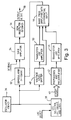
- Fig. 3 shows the block diagram for the OCS electronics.
- the LED's are driven by a square wave signal from an oscillator 36.
- LED selector means into block 38 are used to drive the desired LED.
- the light 40 passing through the optical cell is detected by the photodiodes at block 42.
- the output is then amplified by a pre-filter and then by the logarithmic amplifier at block 44.
- the output of the log amplifier then goes to a band pass filter with differential inputs at block 46.
- the oscillator 36 output pulse wave shape is converted by a voltage level shifter 48 to create a square wave with an average voltage of 0 VDC at.
- the signal is also phase shifted to match the phase shift produced in the optical path.
- This square wave is connected to the reference transistor log amplifier at block 50 which has been made to match the signal log amplifier.
- the circuit parameters have been adjusted to produce a log reference signal. Because the reference square wave is substantially constant with temperature, the log reference signal will have temperature dependence produced only by the log amplifier.
- the output from the reference log amplifier is subtracted from the signal log amplifier output in the next circuit stage. This provides the basic temperature compensation of the OCS. An additional signal is added to the subtraction process to null out the constant component.
- the resulting signal is then demodulated at block 52 for its 1kHz component in the next stage.
- the demodulator is a ⁇ 1 gain circuit which has its gain controlled by the logic level value of the signal from oscillator 36.
- the ⁇ 1 gain chopper circuit has superior demodulation characteristics for this application because it output product is independent of the actual levels of the oscillator signal.
- the demodulator shifts the 1kHz signal down to DC.
- the signal After additional gain and bias voltage adjustment at block 54, the signal has a spectral (DC) component which is related to the ink concentration.
- a low pass filter at block 56 is used to remove unwanted AC components.
- the output voltage 58 is then related to the concentration of the ink, varying approximately linearly with concentration.
- the use of the glass rods in the optical cell is beneficial for several reasons.
- the curvature of the glass rods provides a region with a small gap for transmitting light through the ink, while also allowing the gap to increase away from that region to allow ink to pass through the cell with a small pressure drop.
- the rods provide significantly more rigidity than the glass plate walls used in the prior art.
- the curvature of the outer surface of glass rods, near the LED and the photodetectors serve to focus the light from the LED's through the narrowest section of the optical cell and onto the photodetectors.
- the rods are less likely to produces variations in the gap due to burrs or contamination of the spacers.
Landscapes
- Physics & Mathematics (AREA)
- Health & Medical Sciences (AREA)
- Life Sciences & Earth Sciences (AREA)
- Chemical & Material Sciences (AREA)
- Analytical Chemistry (AREA)
- Biochemistry (AREA)
- General Health & Medical Sciences (AREA)
- General Physics & Mathematics (AREA)
- Immunology (AREA)
- Pathology (AREA)
- Engineering & Computer Science (AREA)
- Quality & Reliability (AREA)
- Investigating Or Analysing Materials By Optical Means (AREA)
- Particle Formation And Scattering Control In Inkjet Printers (AREA)
- Accessory Devices And Overall Control Thereof (AREA)
- Optical Measuring Cells (AREA)
Applications Claiming Priority (2)
| Application Number | Priority Date | Filing Date | Title |
|---|---|---|---|
| US21103598A | 1998-12-14 | 1998-12-14 | |
| US211035 | 1998-12-14 |
Publications (1)
| Publication Number | Publication Date |
|---|---|
| EP1010975A1 true EP1010975A1 (fr) | 2000-06-21 |
Family
ID=22785352
Family Applications (1)
| Application Number | Title | Priority Date | Filing Date |
|---|---|---|---|
| EP99309514A Withdrawn EP1010975A1 (fr) | 1998-12-14 | 1999-11-29 | Capteur optique pour la mesure de la concentration de liquides |
Country Status (3)
| Country | Link |
|---|---|
| EP (1) | EP1010975A1 (fr) |
| JP (1) | JP2000218797A (fr) |
| CA (1) | CA2291966A1 (fr) |
Cited By (5)
| Publication number | Priority date | Publication date | Assignee | Title |
|---|---|---|---|---|
| WO2005090946A1 (fr) * | 2004-03-12 | 2005-09-29 | Mks Instruments, Inc. | Detecteur de concentration d'ozone |
| GB2439307A (en) * | 2006-06-23 | 2007-12-27 | Autonumis Ltd | Drink dispensing apparatus |
| EP1684062B1 (fr) * | 2005-01-24 | 2009-09-30 | Krieg, Gunther, Prof.Dr.Ing. | Procédé et dispositif destinés au réglage de la concentration de composants d'additifs dans un liquide de processus d'imprimerie |
| WO2013118107A1 (fr) * | 2012-02-08 | 2013-08-15 | Hewlett Packard Indigo B.V. | Calcul de la densité optique d'un fluide se déplaçant à travers un espace |
| EP3288766A4 (fr) * | 2015-04-30 | 2018-12-05 | Hewlett-Packard Development Company, L.P. | Capteur de fluide optique microfluidique |
Families Citing this family (5)
| Publication number | Priority date | Publication date | Assignee | Title |
|---|---|---|---|---|
| JP2009222412A (ja) * | 2008-03-13 | 2009-10-01 | Jms Co Ltd | 成分測定用器具及び成分測定用器具を備えた血液透析装置 |
| US8564768B2 (en) * | 2009-04-17 | 2013-10-22 | Schlumberger Technology Corporation | High pressure and high temperature optical spectroscopy cell using spherical surfaced lenses in direct contact with a fluid pathway |
| JP2012237758A (ja) * | 2012-07-23 | 2012-12-06 | Jms Co Ltd | 成分測定用器具及び成分測定用器具を備えた血液透析装置 |
| US20220082504A1 (en) * | 2019-06-04 | 2022-03-17 | Hewlett-Packard Development Company, L.P. | Surface dilution for sensor calibration |
| JP2022185655A (ja) * | 2021-06-03 | 2022-12-15 | アズビル株式会社 | 光学分析装置 |
Citations (4)
| Publication number | Priority date | Publication date | Assignee | Title |
|---|---|---|---|---|
| GB2065878A (en) * | 1979-12-21 | 1981-07-01 | Du Pont | Measuring light transmitted through liquids eg chemical badges |
| JPS59107241A (ja) * | 1982-12-10 | 1984-06-21 | Mitsubishi Electric Corp | 水質計器 |
| US5241189A (en) * | 1992-05-29 | 1993-08-31 | Eastman Kodak Company | Ink concentration sensor for maintaining dye concentration in an ink jet printer |
| US5696592A (en) * | 1996-12-11 | 1997-12-09 | Kuan; Ching Fu | Immersible apparatus for measuring light penetrability of liquids |
-
1999
- 1999-11-29 EP EP99309514A patent/EP1010975A1/fr not_active Withdrawn
- 1999-12-10 CA CA 2291966 patent/CA2291966A1/fr not_active Abandoned
- 1999-12-14 JP JP11354159A patent/JP2000218797A/ja active Pending
Patent Citations (4)
| Publication number | Priority date | Publication date | Assignee | Title |
|---|---|---|---|---|
| GB2065878A (en) * | 1979-12-21 | 1981-07-01 | Du Pont | Measuring light transmitted through liquids eg chemical badges |
| JPS59107241A (ja) * | 1982-12-10 | 1984-06-21 | Mitsubishi Electric Corp | 水質計器 |
| US5241189A (en) * | 1992-05-29 | 1993-08-31 | Eastman Kodak Company | Ink concentration sensor for maintaining dye concentration in an ink jet printer |
| US5696592A (en) * | 1996-12-11 | 1997-12-09 | Kuan; Ching Fu | Immersible apparatus for measuring light penetrability of liquids |
Non-Patent Citations (1)
| Title |
|---|
| PATENT ABSTRACTS OF JAPAN vol. 008, no. 228 (P - 308) 19 October 1984 (1984-10-19) * |
Cited By (12)
| Publication number | Priority date | Publication date | Assignee | Title |
|---|---|---|---|---|
| WO2005090946A1 (fr) * | 2004-03-12 | 2005-09-29 | Mks Instruments, Inc. | Detecteur de concentration d'ozone |
| US7502114B2 (en) | 2004-03-12 | 2009-03-10 | Mks Instruments, Inc. | Ozone concentration sensor |
| US8085401B2 (en) | 2004-03-12 | 2011-12-27 | Mks Instruments, Inc. | Ozone concentration sensor |
| US8339607B2 (en) | 2004-03-12 | 2012-12-25 | Mks Instruments, Inc. | Ozone concentration sensor |
| EP1684062B1 (fr) * | 2005-01-24 | 2009-09-30 | Krieg, Gunther, Prof.Dr.Ing. | Procédé et dispositif destinés au réglage de la concentration de composants d'additifs dans un liquide de processus d'imprimerie |
| DE102005003372B4 (de) | 2005-01-24 | 2024-04-18 | Gunther Krieg | Verfahren und Vorrichtung zum Regeln der Konzentration von Komponenten von Additiven in einer Druck- Prozessflüssigkeit |
| GB2439307A (en) * | 2006-06-23 | 2007-12-27 | Autonumis Ltd | Drink dispensing apparatus |
| WO2013118107A1 (fr) * | 2012-02-08 | 2013-08-15 | Hewlett Packard Indigo B.V. | Calcul de la densité optique d'un fluide se déplaçant à travers un espace |
| CN104204773A (zh) * | 2012-02-08 | 2014-12-10 | 惠普印迪戈股份公司 | 计算穿过间隙的流体的光密度 |
| US9285315B2 (en) | 2012-02-08 | 2016-03-15 | Hewlett-Packard Indigo B.V. | Calculating the optical density of a fluid traveling through a gap |
| EP3288766A4 (fr) * | 2015-04-30 | 2018-12-05 | Hewlett-Packard Development Company, L.P. | Capteur de fluide optique microfluidique |
| US10365226B2 (en) | 2015-04-30 | 2019-07-30 | Hewlett-Packard Development Company, L.P. | Microfluidic optical fluid sensor |
Also Published As
| Publication number | Publication date |
|---|---|
| JP2000218797A (ja) | 2000-08-08 |
| CA2291966A1 (fr) | 2000-06-14 |
Similar Documents
| Publication | Publication Date | Title |
|---|---|---|
| US5241189A (en) | Ink concentration sensor for maintaining dye concentration in an ink jet printer | |
| EP1010975A1 (fr) | Capteur optique pour la mesure de la concentration de liquides | |
| US4834533A (en) | Measuring the refractive index of liquid | |
| US7593107B2 (en) | Method and system for diffusion attenuated total reflection based concentration sensing | |
| US4730922A (en) | Absorbance, turbidimetric, fluorescence and nephelometric photometer | |
| CA1189354A (fr) | Chambre de controle des caracteristiques d'absorption et de fluorescence d'un liquide, par voie optique, a niveau de temperature regle | |
| JP2006177960A (ja) | スペクトル範囲が改良された発光ダイオード分光光度計 | |
| US8325329B2 (en) | Sample detector and measurement device equipped with the same | |
| US7221440B2 (en) | System and method for controlling ink concentration using a refractometer | |
| US7359055B2 (en) | Optical sensor for determining the concentrations of dyes and/or particles in liquid or gaseous media and method for operating the same | |
| WO2006104871A1 (fr) | Densitometre optique a purge d'air | |
| US6789870B2 (en) | Drop quantity calibration method and system | |
| CN105556282A (zh) | 光学吸收监测系统 | |
| GB2097529A (en) | Detecting oil in water | |
| US20240094124A1 (en) | Fluorescence and scatter and absorption spectroscopic apparatus with a sapphire tube and method for analyzing inline low level hydrocarbon in a flow medium | |
| EP0530309A1 (fr) | Analyseurs de gaz | |
| KR102657005B1 (ko) | 잉크 탱크, 잉크 측정 시스템 및 잉크 측정 방법 | |
| US6270178B1 (en) | Method and apparatus for measuring the amount of discharged ink, printing apparatus, and method of measuring the amount of ink discharged in the printing apparatus | |
| WO1994009507A1 (fr) | Systeme ameliore de distribution par fibre optique pour un senseur a fibre optique dans un systeme detecteur luminescent | |
| EP1027592B1 (fr) | Analyseur de gaz par spectrometrie d'absorption non dispersive dans l'infrarouge de type diffusion avec ecoulement de convection | |
| US7372572B2 (en) | Device for photometrically measuring the concentration of a chemical substance in a solution to be measured | |
| JP4910588B2 (ja) | 水質測定装置 | |
| JP2013083528A (ja) | 密着型光学ラインセンサ装置及び有価紙面の鑑別方法 | |
| US7914138B2 (en) | Ink for ink-jet recording, ink cartridge, and ink-jet recording apparatus | |
| CN115015117A (zh) | 一种散透射浊度和多通道比色的水质检测装置及检测方法 |
Legal Events
| Date | Code | Title | Description |
|---|---|---|---|
| PUAI | Public reference made under article 153(3) epc to a published international application that has entered the european phase |
Free format text: ORIGINAL CODE: 0009012 |
|
| AK | Designated contracting states |
Kind code of ref document: A1 Designated state(s): DE FR GB |
|
| AX | Request for extension of the european patent |
Free format text: AL;LT;LV;MK;RO;SI |
|
| RIN1 | Information on inventor provided before grant (corrected) |
Inventor name: MUSSER, MARSHALL Inventor name: SINCLAIR, GARY Inventor name: KING,TOBY Inventor name: LARGE, TIMOTHY Inventor name: MULLINS, RANDAL L. Inventor name: BOWERS, MARK C. Inventor name: ROBERTS, JEFFREY L. Inventor name: LOYD, JOHN C. |
|
| 17P | Request for examination filed |
Effective date: 20001213 |
|
| AKX | Designation fees paid |
Free format text: DE FR GB |
|
| RAP1 | Party data changed (applicant data changed or rights of an application transferred) |
Owner name: EASTMAN KODAK COMPANY |
|
| 17Q | First examination report despatched |
Effective date: 20060926 |
|
| 17Q | First examination report despatched |
Effective date: 20060926 |
|
| STAA | Information on the status of an ep patent application or granted ep patent |
Free format text: STATUS: THE APPLICATION HAS BEEN WITHDRAWN |
|
| 18W | Application withdrawn |
Effective date: 20090810 |