EP1009054B1 - Fuel cell device - Google Patents
Fuel cell device Download PDFInfo
- Publication number
- EP1009054B1 EP1009054B1 EP99124569A EP99124569A EP1009054B1 EP 1009054 B1 EP1009054 B1 EP 1009054B1 EP 99124569 A EP99124569 A EP 99124569A EP 99124569 A EP99124569 A EP 99124569A EP 1009054 B1 EP1009054 B1 EP 1009054B1
- Authority
- EP
- European Patent Office
- Prior art keywords
- fuel cell
- output
- converter
- main body
- voltage
- Prior art date
- Legal status (The legal status is an assumption and is not a legal conclusion. Google has not performed a legal analysis and makes no representation as to the accuracy of the status listed.)
- Expired - Lifetime
Links
Images


Classifications
-
- H—ELECTRICITY
- H01—ELECTRIC ELEMENTS
- H01M—PROCESSES OR MEANS, e.g. BATTERIES, FOR THE DIRECT CONVERSION OF CHEMICAL ENERGY INTO ELECTRICAL ENERGY
- H01M8/00—Fuel cells; Manufacture thereof
- H01M8/04—Auxiliary arrangements, e.g. for control of pressure or for circulation of fluids
- H01M8/04298—Processes for controlling fuel cells or fuel cell systems
- H01M8/04313—Processes for controlling fuel cells or fuel cell systems characterised by the detection or assessment of variables; characterised by the detection or assessment of failure or abnormal function
- H01M8/04537—Electric variables
- H01M8/04604—Power, energy, capacity or load
- H01M8/04626—Power, energy, capacity or load of auxiliary devices, e.g. batteries, capacitors
-
- H—ELECTRICITY
- H01—ELECTRIC ELEMENTS
- H01M—PROCESSES OR MEANS, e.g. BATTERIES, FOR THE DIRECT CONVERSION OF CHEMICAL ENERGY INTO ELECTRICAL ENERGY
- H01M10/00—Secondary cells; Manufacture thereof
- H01M10/42—Methods or arrangements for servicing or maintenance of secondary cells or secondary half-cells
- H01M10/44—Methods for charging or discharging
-
- H—ELECTRICITY
- H01—ELECTRIC ELEMENTS
- H01M—PROCESSES OR MEANS, e.g. BATTERIES, FOR THE DIRECT CONVERSION OF CHEMICAL ENERGY INTO ELECTRICAL ENERGY
- H01M16/00—Structural combinations of different types of electrochemical generators
- H01M16/003—Structural combinations of different types of electrochemical generators of fuel cells with other electrochemical devices, e.g. capacitors, electrolysers
- H01M16/006—Structural combinations of different types of electrochemical generators of fuel cells with other electrochemical devices, e.g. capacitors, electrolysers of fuel cells with rechargeable batteries
-
- H—ELECTRICITY
- H01—ELECTRIC ELEMENTS
- H01M—PROCESSES OR MEANS, e.g. BATTERIES, FOR THE DIRECT CONVERSION OF CHEMICAL ENERGY INTO ELECTRICAL ENERGY
- H01M8/00—Fuel cells; Manufacture thereof
- H01M8/04—Auxiliary arrangements, e.g. for control of pressure or for circulation of fluids
- H01M8/04298—Processes for controlling fuel cells or fuel cell systems
- H01M8/04694—Processes for controlling fuel cells or fuel cell systems characterised by variables to be controlled
- H01M8/04858—Electric variables
- H01M8/04925—Power, energy, capacity or load
- H01M8/04947—Power, energy, capacity or load of auxiliary devices, e.g. batteries, capacitors
-
- H—ELECTRICITY
- H02—GENERATION; CONVERSION OR DISTRIBUTION OF ELECTRIC POWER
- H02J—CIRCUIT ARRANGEMENTS OR SYSTEMS FOR SUPPLYING OR DISTRIBUTING ELECTRIC POWER; SYSTEMS FOR STORING ELECTRIC ENERGY
- H02J7/00—Circuit arrangements for charging or depolarising batteries or for supplying loads from batteries
- H02J7/34—Parallel operation in networks using both storage and other dc sources, e.g. providing buffering
-
- Y—GENERAL TAGGING OF NEW TECHNOLOGICAL DEVELOPMENTS; GENERAL TAGGING OF CROSS-SECTIONAL TECHNOLOGIES SPANNING OVER SEVERAL SECTIONS OF THE IPC; TECHNICAL SUBJECTS COVERED BY FORMER USPC CROSS-REFERENCE ART COLLECTIONS [XRACs] AND DIGESTS
- Y02—TECHNOLOGIES OR APPLICATIONS FOR MITIGATION OR ADAPTATION AGAINST CLIMATE CHANGE
- Y02E—REDUCTION OF GREENHOUSE GAS [GHG] EMISSIONS, RELATED TO ENERGY GENERATION, TRANSMISSION OR DISTRIBUTION
- Y02E60/00—Enabling technologies; Technologies with a potential or indirect contribution to GHG emissions mitigation
- Y02E60/10—Energy storage using batteries
-
- Y—GENERAL TAGGING OF NEW TECHNOLOGICAL DEVELOPMENTS; GENERAL TAGGING OF CROSS-SECTIONAL TECHNOLOGIES SPANNING OVER SEVERAL SECTIONS OF THE IPC; TECHNICAL SUBJECTS COVERED BY FORMER USPC CROSS-REFERENCE ART COLLECTIONS [XRACs] AND DIGESTS
- Y02—TECHNOLOGIES OR APPLICATIONS FOR MITIGATION OR ADAPTATION AGAINST CLIMATE CHANGE
- Y02E—REDUCTION OF GREENHOUSE GAS [GHG] EMISSIONS, RELATED TO ENERGY GENERATION, TRANSMISSION OR DISTRIBUTION
- Y02E60/00—Enabling technologies; Technologies with a potential or indirect contribution to GHG emissions mitigation
- Y02E60/30—Hydrogen technology
- Y02E60/50—Fuel cells
Definitions
- the present invention relates to a fuel cell device. More particularly, it relates to a fuel cell device suitable for a fuel cell such as a solid polymer electrolyte fuel cell in which hydrogen is used as the fuel and the air is employed as the oxidant.
- a fuel cell device suitable for a fuel cell such as a solid polymer electrolyte fuel cell in which hydrogen is used as the fuel and the air is employed as the oxidant.
- Stacking unit cells in each of which an electrolyte layer is held by being sandwiched between a fuel flow field and an air flow field, forms the main body of the fuel cell.
- the fuel flow field and the air flow field are supplied with fuel gas and air, respectively. Then, an electrical chemical reaction is caused to occur, thereby generating the electric power.
- the main body of the fuel cell has a characteristic that, if a load current density is increased, activated polarization of an electrode catalyst, the ohmic loss and the concentration polarization bring about a drop in an output voltage from the fuel cell.
- the main body of the fuel cell is used as the following system:
- the use of a DC-DC converter or a DC-AC converter makes it possible to output, as a constant voltage, a direct current power outputted from the fuel cell.
- the main body of the fuel cell is slow in the response of the output voltage to a variation in the load current density. Because of this, when a sudden change occurs in the external load, the output voltage is temporarily lowered exceedingly, becoming an output voltage smaller than the minimum operation voltage that the external load side requires. This has resulted in a fear that the system itself may come to a halt.
- a secondary battery is located in parallel to the fuel cell and, at the time of the sudden change of the external load, the power is supplied from the secondary battery to the external load so that the external load variation on the fuel cell side is reduced.
- a voltage needed for charging the secondary battery differs from a voltage needed for the load.
- the DC-DC converter or the DC-AC converter be equipped with 2 lines of outputs, i.e., an output for the load and an output for charging the secondary battery, thereby bringing about complexities and cost-up of the appliances.
- the power to be supplied from the secondary battery to the load is outputted to the load by way of the DC-DC converter or the DC-AC converter.
- the power from the secondary battery is multiplied by conversion efficiency of the DC-DC converter or that of the DC-AC converter. This has caused the power loss to occur.
- Patent Abstracts of Japan Vol. 1996, No. 10, 31 October 1996 and JP 08 162136 disclose a fuel cell device comprising a DC/AC converter, an output terminal to an external load, an auxiliary device necessary for driving said fuel cell device, a secondary battery that, when the output from the main body of the fuel cell is lacking, generates an output voltage for driving the auxiliary device, a charge controlling unit for controlling charge of the secondary battery, and a circuit switching controlling unit for controlling supply of the output power from the DC/AC converter to the auxiliary device and the charge controlling unit, and for controlling supply of the output power from the secondary battery to the auxiliary device.
- the fuel cell device includes a main body of the fuel cell, a DC-DC converter or a DC-AC converter for converting a direct current power into a direct current of a predetermined voltage V 1 or an alternating current thereof, the direct current power being outputted from the main body of the fuel cell, an output terminal to an external load, an auxiliary device necessary for driving the fuel cell device, a secondary battery that, when the output from the main body of the fuel cell is lacking, outputs an output voltage V 2 for driving the auxiliary device, the auxiliary device being necessary for driving the fuel cell device, a charge controlling unit for controlling charge of the secondary battery, and a circuit-switching controlling unit for controlling supply of the output current from the DC-DC converter or the DC-AC converter to the output terminal to the external load, the auxiliary device and the charge controlling unit, and for controlling supply of the output power from the secondary battery, the auxiliary device being necessary for driving the fuel cell device, wherein, when the output voltage V from the main body of the
- the configuration of another fuel cell device related to the present invention is as follows: When the output voltage V from the main body of the fuel cell becomes higher than a predetermined recovering voltage V 6 after the sudden change of the external load of the fuel cell device, the output to the charge controlling unit is restarted, and when the output voltage V from the main body of the fuel cell becomes higher than a recoverying voltage V 7, the output to the auxiliary device is restarted, the auxiliary device being necessary for driving the fuel cell device.
- the first embodiment of the invention is defined by the features of claim 1.
- the second embodiment of the invention is defined by the features of claim 2.
- a value of auxiliary device output from the auxiliary device is made large when the output voltage V is lower than a predetermined voltage, and is made small when the output voltage V is higher than the predetermined voltage, the auxiliary device being necessary for driving the fuel cell device.
- the plurality of driving auxiliary devices are driven in series when they are driven by the output from the DC-DC converter or the DC-AC converter, and are driven in parallel to each other when they are driven by the output from the secondary battery.
- FIG. 1 shows a schematic configuration diagram of a fuel cell device that employs a main body of a fuel cell that is an embodiment of the present invention.
- a reference numeral 1 denotes the main body of the fuel cell formed by stacking a plurality of unit cells in each of which an electrolyte layer is held by being sandwiched between a fuel flow field and an air flow field.
- the fuel flow field and the air flow field in each cell are supplied with fuel gas and air, respectively, and an electrical chemical reaction is caused to occur, thereby generating the electric power.
- a numeral 2 denotes an auxiliary device for supplying the main body of the fuel cell 1 with hydrogen gas and air.
- a numeral 3 denotes a DC-DC converter for converting a direct current power, which is outputted from the main body of the fuel cell 1, into a direct current power of a predetermined voltage V 1.
- a numeral 4 denotes an output terminal to an external load, which supplies the external load with the power.
- a numeral 5 denotes a secondary battery that outputs an output voltage V 2 for driving the auxiliary device 2 when the output voltage from the main body of the fuel cell 1 is lowered.
- a numeral 6 denotes a charge controlling unit for controlling charge of the secondary battery 5.
- a numeral 7 denotes a circuit-switching controlling unit for controlling supply of the output power from the DC-DC converter 3 to the external load output terminal 4, the auxiliary device 2 and the charge controlling unit 6, and for controlling supply of the output power from the secondary battery 5 to the auxiliary device 2.
- a numeral 8 denotes a control switch for controlling the external output from the main body of the fuel cell 1.
- a numeral 9 denotes a sensor unit for monitoring the output voltage from the main body of the fuel cell 1 so as to provide the circuit-switching controlling unit 7 with a control signal.
- a numeral 10 denotes a cell protecting switch A for breaking a circuit between the secondary battery 5 and the charge controlling unit 6.
- a numeral 11 denotes a cell protecting switch B for breaking the secondary battery 5 from the circuit-switching controlling unit 7.
- the protecting switches A 10, B 11 for protecting the secondary battery 5 are closed, and after supplying the main body of the fuel cell 1 with the hydrogen, i.e., the fuel, the control switch 8 is closed.
- This procedure completes starting-up of the fuel cell device.
- the direct current power caused by the main body of the fuel cell 1 is converted into the direct current power of the predetermined voltage V 1 by the DC-DC converter 3, then being steadily supplied to the external load output terminal 4 through the circuit-switching controlling unit 7.
- V 6 and V 7 are given by the following formulae (2), (3) and (4): V 6 ⁇ V 7 V 3 ⁇ V 7 V 4 ⁇ V 6
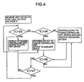
- FIG. 4 shows a circuit-switching algorithm for the above-mentioned circuit-switching controlling unit 7 in the fuel cell device.
- the DC-DC converter 3 is configured to be equipped with 1 line of output. Moreover, since the secondary battery output voltage V 2 is lower than the output voltage V 1 from the DC-DC converter 3, configuration of the charge controlling unit 6 becomes simpler. Also, the output power from the secondary battery 5 is supplied without the intervention of the DC-DC converter 3, which allows the power loss to be reduced. Incidentally, it is allowable to use the DC-AC converter instead of the DC-DC converter 3 used in the above-mentioned fuel cell device.
- FIG. 5 shows a schematic configuration diagram of a fuel cell device that employs a main body of a fuel cell that is another embodiment of the present invention.
- the fuel cell device of the configuration employed in the Embodiment 1 when a fan for supplying the main body of the fuel cell 1 with air is used as the auxiliary device 2, there is provided an auxiliary device output controlling unit 12 that controls the rotation speed of the fan in accordance with the signal from the sensor unit 9 for monitoring the value of the output voltage V. If the external load is heavy and the value of the output voltage V from the main body of the fuel cell 1 is small, the auxiliary device output controlling unit 12 increases the rotation speed of the fan. Conversely, if the external load is light and the value of the output voltage V from the main body of the fuel cell 1 is large, the auxiliary device output controlling unit 12 decreases the rotation speed of the fan.
- the fuel cell device configured as described above allows an efficient operation to be embodied in the following manner: When, at the time of a light load, the main body of the fuel cell 1 does not require large amount of air, the fuel cell device drops the rotation speed of the fan, thereby reducing a power loss. Also, when, at the time of a heavy load, the main body of the fuel cell 1 requires large amount of, the fuel cell device raises the rotation speed of the fan, thereby performing sufficient power generation.
- FIG. 6 shows a schematic configuration diagram of a fuel cell device that employs a main body of a fuel cell that is still another embodiment of the present invention.
- the fuel cell device of the configuration employed in the Embodiment 1 as the auxiliary devices 2, there are provided the 1st fan 2a and the 2nd fan 2b for supplying the main body of the fuel cell 1 with air.
- a circuit-switching controlling unit 7 having a function that, when the output voltage V from the main body of the fuel cell 1 becomes equal to a predetermined voltage V 4 and based on the signal from the sensor unit 9, switches driving outputs toward the 1st fan 2a and the 2nd fan 2b to the output from the DC-DC converter 3 and the output from the secondary battery 5.
- the 1st fan 2a and the 2nd fan 2b are driven in series by the output voltage V1 from the DC-DC converter 3. Also, when the value of the output voltage V becomes lower than the predetermined voltage V 4, the 1st fan 2a and the 2nd fan 2b are driven in parallel to each other by the output voltage V 2 from the secondary battery 5.
- the fuel cell device of the embodiment 3 configured as described above makes it possible to minimize the variation of driving voltage for each fan in both cases where the fans are driven by the output voltage V1 from the DC-DC converter 3 and where the fans are driven by the output voltage V 2 from the secondary battery 5. Accordingly, it becomes possible to maintain air-supplying capabilities of the fans.
- the employment of the configurations of the fuel cell device according to the present invention makes it possible to accomplish provision of the simple, low cost and highly effective fuel cell device that permits the stable external load output to be obtained even at the time of the sudden change of the external load.
Description
- The present invention relates to a fuel cell device. More particularly, it relates to a fuel cell device suitable for a fuel cell such as a solid polymer electrolyte fuel cell in which hydrogen is used as the fuel and the air is employed as the oxidant.
- Stacking unit cells, in each of which an electrolyte layer is held by being sandwiched between a fuel flow field and an air flow field, forms the main body of the fuel cell. The fuel flow field and the air flow field are supplied with fuel gas and air, respectively. Then, an electrical chemical reaction is caused to occur, thereby generating the electric power. Moreover, the main body of the fuel cell has a characteristic that, if a load current density is increased, activated polarization of an electrode catalyst, the ohmic loss and the concentration polarization bring about a drop in an output voltage from the fuel cell. On account of this, when power output is performed to an external load that consumes the power with the fuel cell as the power supply, the main body of the fuel cell is used as the following system: The use of a DC-DC converter or a DC-AC converter makes it possible to output, as a constant voltage, a direct current power outputted from the fuel cell. Also, the main body of the fuel cell is slow in the response of the output voltage to a variation in the load current density. Because of this, when a sudden change occurs in the external load, the output voltage is temporarily lowered exceedingly, becoming an output voltage smaller than the minimum operation voltage that the external load side requires. This has resulted in a fear that the system itself may come to a halt.
- In order to solve this problem, in publications such as JP-A-50-116925, the following system has been proposed: A secondary battery is located in parallel to the fuel cell and, at the time of the sudden change of the external load, the power is supplied from the secondary battery to the external load so that the external load variation on the fuel cell side is reduced.
- However, in the system where, as illustrated in FIG.2, the power is supplied from the secondary battery to the external load at the time of the sudden change of the external load, a voltage needed for charging the secondary battery differs from a voltage needed for the load. This has required that the DC-DC converter or the DC-AC converter be equipped with 2 lines of outputs, i.e., an output for the load and an output for charging the secondary battery, thereby bringing about complexities and cost-up of the appliances.
- Also, as illustrated in FIG.3, in the case of a system where the output for charging the secondary battery is branched from the output line for the load, it turns out that the output line for the secondary battery is inputted into the DC-DC converter or the DC-AC converter.
- At that time, the power to be supplied from the secondary battery to the load is outputted to the load by way of the DC-DC converter or the DC-AC converter. As the result, the power from the secondary battery is multiplied by conversion efficiency of the DC-DC converter or that of the DC-AC converter. This has caused the power loss to occur.
- Patent Abstracts of Japan Vol. 1996, No. 10, 31 October 1996 and JP 08 162136 disclose a fuel cell device comprising a DC/AC converter, an output terminal to an external load, an auxiliary device necessary for driving said fuel cell device, a secondary battery that, when the output from the main body of the fuel cell is lacking, generates an output voltage for driving the auxiliary device, a charge controlling unit for controlling charge of the secondary battery, and a circuit switching controlling unit for controlling supply of the output power from the DC/AC converter to the auxiliary device and the charge controlling unit, and for controlling supply of the output power from the secondary battery to the auxiliary device.
- In order to solve the above-described problems, it is an object of the present invention to effectively supply the fuel cell device with the power from the secondary battery at the time of the sudden change of the external load, and to simplify the system and to provide the fuel cell device that is inexpensive.
- In order to solve the above-described problems, the fuel cell device according to the present invention includes a main body of the fuel cell, a DC-DC converter or a DC-AC converter for converting a direct current power into a direct current of a
predetermined voltage V 1 or an alternating current thereof, the direct current power being outputted from the main body of the fuel cell, an output terminal to an external load, an auxiliary device necessary for driving the fuel cell device, a secondary battery that, when the output from the main body of the fuel cell is lacking, outputs anoutput voltage V 2 for driving the auxiliary device, the auxiliary device being necessary for driving the fuel cell device, a charge controlling unit for controlling charge of the secondary battery, and a circuit-switching controlling unit for controlling supply of the output current from the DC-DC converter or the DC-AC converter to the output terminal to the external load, the auxiliary device and the charge controlling unit, and for controlling supply of the output power from the secondary battery, the auxiliary device being necessary for driving the fuel cell device, wherein, when the output voltage V from the main body of the fuel cell becomes lower than apredetermined voltage V 3 at the time of a sudden change of the external load, the output to the charge controlling unit is stopped, and in addition, when the output voltage V from the main body of the fuel cell becomes lower than apredetermined voltage V 4, the output to the auxiliary device is switched from the output from the DC-DC converter or the DC-AC converter to the output from the secondary battery, the auxiliary device being necessary for driving the fuel cell device, the relation between theoutput voltage V 1 from the DC-DC converter or the DC-AC converter and theoutput voltage V 2 from the secondary battery being so set as to satisfyV 1 >V 2. - The configuration of another fuel cell device related to the present invention is as follows: When the output voltage V from the main body of the fuel cell becomes higher than a predetermined recovering
voltage V 6 after the sudden change of the external load of the fuel cell device, the output to the charge controlling unit is restarted, and when the output voltage V from the main body of the fuel cell becomes higher than arecoverying voltage V 7, the output to the auxiliary device is restarted, the auxiliary device being necessary for driving the fuel cell device. - The employment of the configuration as described above permits a stable load output to be obtained even at the time of the sudden change of the external load, thus making it possible to provide the fuel cell device that is simple, inexpensive and highly effective.
-
- FIG. 1 is a schematic configuration diagram of a power supply system that employs the solid polymer electrolyte fuel cell in an embodiment of the present invention;
- FIG. 2 is a schematic configuration diagram of a conventional power supply system;
- FIG. 3 is a schematic configuration diagram of a conventional power supply system;
- FIG. 4 is a flow chart for showing an algorithm for the circuit-switching control based on the output voltage V from the fuel cell;
- FIG. 5 is a schematic configuration diagram of a power supply system that employs the solid polymer electrolyte fuel cell in an embodiment of the present invention; and
- FIG. 6 is a schematic configuration diagram of a power supply system that employs the solid polymer electrolyte fuel cell in an embodiment of the present invention.
- The first embodiment of the invention is defined by the features of
claim 1. - The second embodiment of the invention is defined by the features of
claim 2. - Moreover, based on the output voltage V from the main body of the fuel cell, a value of auxiliary device output from the auxiliary device is made large when the output voltage V is lower than a predetermined voltage, and is made small when the output voltage V is higher than the predetermined voltage, the auxiliary device being necessary for driving the fuel cell device.
- Also, in the case where there exist a plurality of the auxiliary devices that are necessary for driving the fuel cell device, the plurality of driving auxiliary devices are driven in series when they are driven by the output from the DC-DC converter or the DC-AC converter, and are driven in parallel to each other when they are driven by the output from the secondary battery.
- FIG. 1 shows a schematic configuration diagram of a fuel cell device that employs a main body of a fuel cell that is an embodiment of the present invention. In FIG. 1, a
reference numeral 1 denotes the main body of the fuel cell formed by stacking a plurality of unit cells in each of which an electrolyte layer is held by being sandwiched between a fuel flow field and an air flow field. The fuel flow field and the air flow field in each cell are supplied with fuel gas and air, respectively, and an electrical chemical reaction is caused to occur, thereby generating the electric power. Anumeral 2 denotes an auxiliary device for supplying the main body of thefuel cell 1 with hydrogen gas and air. Anumeral 3 denotes a DC-DC converter for converting a direct current power, which is outputted from the main body of thefuel cell 1, into a direct current power of apredetermined voltage V 1. Anumeral 4 denotes an output terminal to an external load, which supplies the external load with the power. Anumeral 5 denotes a secondary battery that outputs anoutput voltage V 2 for driving theauxiliary device 2 when the output voltage from the main body of thefuel cell 1 is lowered. Anumeral 6 denotes a charge controlling unit for controlling charge of thesecondary battery 5. Anumeral 7 denotes a circuit-switching controlling unit for controlling supply of the output power from the DC-DC converter 3 to the externalload output terminal 4, theauxiliary device 2 and thecharge controlling unit 6, and for controlling supply of the output power from thesecondary battery 5 to theauxiliary device 2. Anumeral 8 denotes a control switch for controlling the external output from the main body of thefuel cell 1. Anumeral 9 denotes a sensor unit for monitoring the output voltage from the main body of thefuel cell 1 so as to provide the circuit-switching controllingunit 7 with a control signal. Anumeral 10 denotes a cell protecting switch A for breaking a circuit between thesecondary battery 5 and thecharge controlling unit 6. Anumeral 11 denotes a cell protecting switch B for breaking thesecondary battery 5 from the circuit-switching controllingunit 7. These respective configuration units constitute the fuel cell device. - In the fuel cell device including the members as described above, the protecting
switches A 10,B 11 for protecting thesecondary battery 5 are closed, and after supplying the main body of thefuel cell 1 with the hydrogen, i.e., the fuel, thecontrol switch 8 is closed. This procedure completes starting-up of the fuel cell device. When the starting-up is completed and the main body of thefuel cell 1 is put into a steady operation, the direct current power caused by the main body of thefuel cell 1 is converted into the direct current power of thepredetermined voltage V 1 by the DC-DC converter 3, then being steadily supplied to the externalload output terminal 4 through the circuit-switching controllingunit 7. In the state where the power output to the external load is being steady, if a sudden change in the load occurs and then the output voltage V from the main body of thefuel cell 1 is lowered temporarily and becomes lower than apredetermined voltage V 3, the output to thecharge controlling unit 6 is stopped at the circuit-switching controllingunit 7 in accordance with the signal from thesensor unit 9. In addition, when the output voltage V is lowered even further and becomes lower than a certainspecified voltage V 4, the output to theauxiliary device 2 is stopped at the circuit-switching controllingunit 7 in accordance with the signal from thesensor unit 9. At the same time, the output power to theauxiliary device 2 is switched to the output power from thesecondary battery 5. This procedure reduces the load imposed on the main body of thefuel cell 1, thereby making it possible to maintain the value of the output voltage V at a value higher than a minimumoperation voltage V 5 at the load side. - Here, the relation that holds among
V 3,V 4 andV 5 is given by the following formula (1):
- After that, when, on account of recovery of the output voltage V from the main body of the
fuel cell 1 or the reduction of the external load, the output voltage V becomes higher than a predeterminedrecoverying voltage V 6, the output to theauxiliary device 2 is restarted at the circuit-switching controllingunit 7 in accordance with the signal from thesensor unit 9. At the same time, the output power to theauxiliary device 2 is switched from the output power from thesecondary battery 5 to that from the DC-DC converter 3. In addition, when the value of the output voltage V is heightened even further and becomes higher than a predeterminedrecoverying voltage V 7, the output to thecharge controlling unit 6 is restarted at the circuit-switching controllingunit 7 in accordance with the signal from thesensor unit 9. This procedure makes it possible to supply the external load with stable power. - Here, the relation between
V 6 andV 7 is given by the following formulae (2), (3) and (4):


- Furthermore, the relation between the
output voltage V 1 from the DC-DC converter 3 and the secondary batteryoutput voltage V 2 is so set as to satisfyV 1 >V 2. - FIG. 4 shows a circuit-switching algorithm for the above-mentioned circuit-switching
controlling unit 7 in the fuel cell device. - In the fuel cell device configured as described above, it turns out that the DC-
DC converter 3 is configured to be equipped with 1 line of output. Moreover, since the secondary batteryoutput voltage V 2 is lower than theoutput voltage V 1 from the DC-DC converter 3, configuration of thecharge controlling unit 6 becomes simpler. Also, the output power from thesecondary battery 5 is supplied without the intervention of the DC-DC converter 3, which allows the power loss to be reduced. Incidentally, it is allowable to use the DC-AC converter instead of the DC-DC converter 3 used in the above-mentioned fuel cell device. - FIG. 5 shows a schematic configuration diagram of a fuel cell device that employs a main body of a fuel cell that is another embodiment of the present invention. In the fuel cell device of the configuration employed in the
Embodiment 1, when a fan for supplying the main body of thefuel cell 1 with air is used as theauxiliary device 2, there is provided an auxiliary deviceoutput controlling unit 12 that controls the rotation speed of the fan in accordance with the signal from thesensor unit 9 for monitoring the value of the output voltage V. If the external load is heavy and the value of the output voltage V from the main body of thefuel cell 1 is small, the auxiliary deviceoutput controlling unit 12 increases the rotation speed of the fan. Conversely, if the external load is light and the value of the output voltage V from the main body of thefuel cell 1 is large, the auxiliary deviceoutput controlling unit 12 decreases the rotation speed of the fan. - The fuel cell device configured as described above allows an efficient operation to be embodied in the following manner: When, at the time of a light load, the main body of the
fuel cell 1 does not require large amount of air, the fuel cell device drops the rotation speed of the fan, thereby reducing a power loss. Also, when, at the time of a heavy load, the main body of thefuel cell 1 requires large amount of, the fuel cell device raises the rotation speed of the fan, thereby performing sufficient power generation. - FIG. 6 shows a schematic configuration diagram of a fuel cell device that employs a main body of a fuel cell that is still another embodiment of the present invention. In the fuel cell device of the configuration employed in the
Embodiment 1, as theauxiliary devices 2, there are provided the1st fan 2a and the2nd fan 2b for supplying the main body of thefuel cell 1 with air. In addition, there is further provided a circuit-switchingcontrolling unit 7 having a function that, when the output voltage V from the main body of thefuel cell 1 becomes equal to apredetermined voltage V 4 and based on the signal from thesensor unit 9, switches driving outputs toward the1st fan 2a and the2nd fan 2b to the output from the DC-DC converter 3 and the output from thesecondary battery 5. - When the output voltage V from the main body of the
fuel cell 1 is higher than thepredetermined voltage V 4, the1st fan 2a and the2nd fan 2b are driven in series by the output voltage V1 from the DC-DC converter 3. Also, when the value of the output voltage V becomes lower than thepredetermined voltage V 4, the1st fan 2a and the2nd fan 2b are driven in parallel to each other by theoutput voltage V 2 from thesecondary battery 5. - The fuel cell device of the
embodiment 3 configured as described above makes it possible to minimize the variation of driving voltage for each fan in both cases where the fans are driven by the output voltage V1 from the DC-DC converter 3 and where the fans are driven by theoutput voltage V 2 from thesecondary battery 5. Accordingly, it becomes possible to maintain air-supplying capabilities of the fans. - At this time, however, the relation between the DC-DC converter
output voltage V 1 and the secondary batteryoutput voltage V 2 is so set as to satisfyV 1 >V 2. - Incidentally, it is allowable to use the DC-AC converter instead of the DC-
DC converter 3 used in the above-mentioned fuel cell device. - As described above, the employment of the configurations of the fuel cell device according to the present invention makes it possible to accomplish provision of the simple, low cost and highly effective fuel cell device that permits the stable external load output to be obtained even at the time of the sudden change of the external load.
Claims (4)
- A fuel cell device, comprising:a main body of a fuel cell (1),a DC-DC converter (3) or a DC-AC converter for converting direct current power into direct current power of a predetermined voltage V 1 or an alternating current power thereof so as to output said direct or alternating current power, said direct current power being outputted from said main body of the fuel cell (1),an output terminal (4) to an external load,an auxiliary device (2) necessary for driving said fuel cell device,a secondary battery (5) that, when said output from said main body of the fuel cell (1) is lacking, generates an output voltage V 2 for driving said auxiliary device (2), said auxiliary device (2) being necessary for driving said fuel cell device,a charge controlling unit (6) for controlling charge of said secondary battery (5), anda circuit-switching controlling unit (7) for controlling supply of said output power from said DC-DC converter (3) or said DC-AC converter to said auxiliary device (2) and said charge controlling unit (6), and for controlling supply of said output power from said secondary battery (5) to said auxiliary device (2) being necessary for driving said fuel cell device,
characterized in that the circuit-switching controlling unit (7) is also configured for controlling supply of said output power from said DC-DC converter (3) or said DC-AC converter to said output terminal (4) to said external load, the relation between said output voltage V 1 from said DC-DC converter (3) or said DC-AC converter and said secondary battery output voltage V 2 is so set as to satisfy V 1 > V 2. and when said output voltage V from said main body of the fuel cell (1) becomes lower than a predetermined voltage V 3 at the time of a sudden change of said external load, said output to said charge controlling unit (6) is stopped, and when said output voltage V from said main body of the fuel cell (1) is lowered even further and becomes lower than a predetermined voltage V 4, said output to said auxiliary device (2) is switched from said output from said DC-DC converter (3) or said DC-AC converter to said output from said secondary battery (5), said auxiliary device (2) being necessary for driving said fuel cell device. - A fuel cell device as claimed in claim 1, wherein when said output voltage V from said main body of the fuel cell (1) becomes higher than a predetermined recoverying voltage V 6, said output to said charge controlling unit (6) is restarted, and when said output voltage V from said main body of the fuel cell (1) becomes higher than a recoverying voltage V 7, said output to said auxiliary device (2) is restarted, said auxiliary device (2) being necessary for driving said fuel cell device.
- The fuel cell device as claimed in Claim 1 or 2, wherein, based on said output voltage V from said main body of the fuel cell (1), a value of output from said auxiliary device (2) is increased when said output voltage V is lower than a predetermined voltage, said value of said auxiliary device output being lowered when said output voltage V is higher than said predetermined voltage, said auxiliary device (2) being necessary for driving said fuel cell device.
- The fuel cell device as claimed in Claim 1, 2 or 3 wherein there are provided a plurality of said auxiliary devices (2), said auxiliary devices (2) being necessary for driving said fuel cell device, when said plurality of driving auxiliary devices (2a), (2b) are driven by said output from said DC-DC converter (3) or said DC-AC converter, said plurality of auxiliary devices (2a), (2b) being driven in series to each other, when driven by said secondary battery output, said plurality of auxiliary devices (2a), (2b) being driven in parallel to each other.
Applications Claiming Priority (2)
| Application Number | Priority Date | Filing Date | Title |
|---|---|---|---|
| JP35105198A JP4096430B2 (en) | 1998-12-10 | 1998-12-10 | Fuel cell device |
| JP35105198 | 1998-12-10 |
Publications (3)
| Publication Number | Publication Date |
|---|---|
| EP1009054A2 EP1009054A2 (en) | 2000-06-14 |
| EP1009054A3 EP1009054A3 (en) | 2003-05-21 |
| EP1009054B1 true EP1009054B1 (en) | 2006-03-08 |
Family
ID=18414718
Family Applications (1)
| Application Number | Title | Priority Date | Filing Date |
|---|---|---|---|
| EP99124569A Expired - Lifetime EP1009054B1 (en) | 1998-12-10 | 1999-12-09 | Fuel cell device |
Country Status (5)
| Country | Link |
|---|---|
| US (1) | US6215272B1 (en) |
| EP (1) | EP1009054B1 (en) |
| JP (1) | JP4096430B2 (en) |
| CA (1) | CA2291860C (en) |
| DE (1) | DE69930194T2 (en) |
Cited By (1)
| Publication number | Priority date | Publication date | Assignee | Title |
|---|---|---|---|---|
| US7632583B2 (en) | 2003-05-06 | 2009-12-15 | Ballard Power Systems Inc. | Apparatus for improving the performance of a fuel cell electric power system |
Families Citing this family (49)
| Publication number | Priority date | Publication date | Assignee | Title |
|---|---|---|---|---|
| KR100652613B1 (en) * | 2000-12-30 | 2006-12-01 | 주식회사 엘지이아이 | Power source supply apparatus for electric machine |
| US6824905B2 (en) | 2001-01-15 | 2004-11-30 | Casio Computer Co., Ltd. | Power supply system and device driven by power supply system |
| US6504339B2 (en) * | 2001-02-08 | 2003-01-07 | Plug Power Inc. | Technique and apparatus to control the charging of a battery using a fuel cell |
| WO2003034523A1 (en) * | 2001-10-11 | 2003-04-24 | Hitachi, Ltd. | Home-use fuel cell system |
| JP2005513722A (en) * | 2001-12-14 | 2005-05-12 | バラード パワー システムズ インコーポレイテッド | Control of hybrid fuel cell system |
| US6573682B1 (en) | 2001-12-14 | 2003-06-03 | Ballard Power Systems Inc. | Fuel cell system multiple stage voltage control method and apparatus |
| US7144646B2 (en) * | 2001-12-14 | 2006-12-05 | Ballard Power Systems Inc. | Method and apparatus for multiple mode control of voltage from a fuel cell system |
| US6841275B2 (en) | 2001-12-14 | 2005-01-11 | Ballard Power Systems Inc. | Method and apparatus for controlling voltage from a fuel cell system |
| JP2005526363A (en) * | 2002-05-16 | 2005-09-02 | バラード パワー システムズ インコーポレイティド | Power facility with an array of adjustable fuel cell systems |
| FI118553B (en) * | 2002-06-28 | 2007-12-14 | Enfucell Oy | Apparatus and method for producing electric power and power source |
| JP2004127618A (en) * | 2002-09-30 | 2004-04-22 | Toshiba Corp | Electronic device system, battery unit, and operation control method of battery unit |
| JP3821081B2 (en) * | 2002-09-30 | 2006-09-13 | 日本電気株式会社 | FUEL CELL, PORTABLE DEVICE EQUIPPED WITH THE SAME AND FUEL CELL OPERATION METHOD |
| JP3912249B2 (en) * | 2002-09-30 | 2007-05-09 | 日本電気株式会社 | Fuel cell operation method and portable device equipped with fuel cell |
| JP3704123B2 (en) * | 2002-12-27 | 2005-10-05 | 株式会社東芝 | Electronic equipment and battery unit |
| US6838923B2 (en) | 2003-05-16 | 2005-01-04 | Ballard Power Systems Inc. | Power supply and ultracapacitor based battery simulator |
| US7419734B2 (en) * | 2003-05-16 | 2008-09-02 | Ballard Power Systems, Inc. | Method and apparatus for fuel cell systems |
| DE112004001132D2 (en) * | 2003-07-01 | 2006-03-02 | Deutsch Zentr Luft & Raumfahrt | Control of fuel cells |
| US7687167B2 (en) | 2003-07-18 | 2010-03-30 | Panasonic Corporation | Power supply unit |
| JP2005078925A (en) * | 2003-08-29 | 2005-03-24 | Toshiba Corp | Battery unit and feeding control method |
| DE10342146A1 (en) * | 2003-09-12 | 2005-04-07 | Daimlerchrysler Ag | Fuel cell unit monitoring process for motor vehicles measures output values of the fuel cell to determine proper operation |
| JP4791689B2 (en) | 2003-10-06 | 2011-10-12 | パナソニック株式会社 | Power supply |
| DE102004001298A1 (en) * | 2004-01-08 | 2005-07-28 | Daimlerchrysler Ag | Fuel cell system with a fuel cell stack and at least one electrical energy storage device |
| US20050184594A1 (en) * | 2004-02-20 | 2005-08-25 | Fredette Steven J. | Electric storage augmentation of fuel cell response to AC system transients |
| WO2005083868A1 (en) * | 2004-02-27 | 2005-09-09 | Shindengen Electric Manufacturing Co., Ltd. | Charger, dc/dc converter having that charger, and control circuit thereof |
| JP2005304179A (en) * | 2004-04-12 | 2005-10-27 | Toyota Motor Corp | Drive system and moving body mounted with the same |
| US7521138B2 (en) * | 2004-05-07 | 2009-04-21 | Ballard Power Systems Inc. | Apparatus and method for hybrid power module systems |
| JP4164050B2 (en) * | 2004-07-29 | 2008-10-08 | 株式会社日立製作所 | Grid interconnection device |
| JP4515235B2 (en) * | 2004-11-25 | 2010-07-28 | 株式会社リコー | Electronic device, fuel cell control method |
| JP2006217780A (en) * | 2005-02-07 | 2006-08-17 | Yamaha Motor Co Ltd | Inverter ac power plant |
| EP1881580A4 (en) * | 2005-05-12 | 2015-08-26 | Shindengen Electric Mfg | Dc/dc converter |
| JP2007020319A (en) * | 2005-07-08 | 2007-01-25 | Yamaha Motor Co Ltd | Dc power supply |
| FR2888685A1 (en) * | 2005-07-18 | 2007-01-19 | St Microelectronics Sa | CONTINUOUS-CONTINUOUS CONVERTER-CONTINUATOR |
| JP5157122B2 (en) * | 2006-10-25 | 2013-03-06 | 株式会社日立製作所 | Polymer electrolyte fuel cell |
| US7977911B2 (en) * | 2007-02-08 | 2011-07-12 | O2 Micro, Inc. | Power supply topology |
| JP5042143B2 (en) * | 2007-12-05 | 2012-10-03 | パナソニック株式会社 | Fuel cell power generation system |
| WO2009072284A1 (en) | 2007-12-05 | 2009-06-11 | Panasonic Corporation | Fuel cell power generation system |
| JP5480086B2 (en) * | 2010-09-24 | 2014-04-23 | 本田技研工業株式会社 | Method for stopping operation of fuel cell system |
| US20130057071A1 (en) * | 2011-09-06 | 2013-03-07 | Raytheon Company | Fuel cell battery charge/discharge management system and method |
| CA2869203C (en) | 2012-04-02 | 2021-08-10 | Hydrogenics Corporation | Method and apparatus for starting a fuel cell from a discharged state |
| US10084196B2 (en) | 2012-05-04 | 2018-09-25 | Hydrogenics Corporation | System and method for controlling fuel cell module |
| CN103683887B (en) * | 2012-09-20 | 2016-04-20 | 安徽动力源科技有限公司 | Control method, the device of a kind of micropower low-power consumption DC-DC change-over circuit and this circuit |
| CN102862491B (en) * | 2012-09-28 | 2014-09-03 | 引峰新能源科技(上海)有限公司 | Compact type fuel battery power supply system |
| CN102881956B (en) * | 2012-09-28 | 2014-07-23 | 引峰新能源科技(上海)有限公司 | Hybrid power source energy management method of fuel battery |
| CN106133997B (en) | 2013-10-02 | 2020-01-14 | 水吉能公司 | Quick start type fuel cell |
| US11309556B2 (en) | 2013-10-02 | 2022-04-19 | Hydrogenics Corporation | Fast starting fuel cell |
| KR101637720B1 (en) * | 2014-11-07 | 2016-07-08 | 현대자동차주식회사 | Control method of fuel cell system |
| KR101822232B1 (en) * | 2015-06-24 | 2018-01-26 | 현대자동차주식회사 | Power net system of fuel cell vehicle and method for controlling the same |
| CN108092371B (en) * | 2016-11-15 | 2020-04-03 | 华为技术有限公司 | Charging and discharging device |
| JP7359791B2 (en) * | 2021-01-25 | 2023-10-11 | 本田技研工業株式会社 | fuel cell system |
Family Cites Families (8)
| Publication number | Priority date | Publication date | Assignee | Title |
|---|---|---|---|---|
| JPS50116925A (en) | 1974-02-28 | 1975-09-12 | ||
| JPS63289773A (en) * | 1987-05-20 | 1988-11-28 | Fuji Electric Co Ltd | Fuel cell power generator |
| JP2932607B2 (en) * | 1990-05-23 | 1999-08-09 | 日産自動車株式会社 | Electric car |
| US5389825A (en) * | 1991-04-24 | 1995-02-14 | Aisin Aw Co., Ltd. | System of controlling changeover of an electric power source for an electric motor vehicle |
| FR2709873B1 (en) * | 1993-09-06 | 1995-10-20 | Imra Europe Sa | Fuel cell voltage generator. |
| JP3029185B2 (en) * | 1994-04-12 | 2000-04-04 | キヤノン株式会社 | Islanding prevention device, distributed power generation device and power generation system using the same |
| JPH08162136A (en) * | 1994-12-07 | 1996-06-21 | Fuji Electric Co Ltd | Fuel cell generating device |
| AP1042A (en) * | 1996-12-20 | 2002-02-08 | Manuel Dos Santos Da Ponte | Hybrid generator apparatus. |
-
1998
- 1998-12-10 JP JP35105198A patent/JP4096430B2/en not_active Expired - Lifetime
-
1999
- 1999-12-07 CA CA002291860A patent/CA2291860C/en not_active Expired - Fee Related
- 1999-12-09 EP EP99124569A patent/EP1009054B1/en not_active Expired - Lifetime
- 1999-12-09 US US09/457,401 patent/US6215272B1/en not_active Expired - Lifetime
- 1999-12-09 DE DE69930194T patent/DE69930194T2/en not_active Expired - Lifetime
Cited By (1)
| Publication number | Priority date | Publication date | Assignee | Title |
|---|---|---|---|---|
| US7632583B2 (en) | 2003-05-06 | 2009-12-15 | Ballard Power Systems Inc. | Apparatus for improving the performance of a fuel cell electric power system |
Also Published As
| Publication number | Publication date |
|---|---|
| JP2000173636A (en) | 2000-06-23 |
| DE69930194T2 (en) | 2006-08-03 |
| DE69930194D1 (en) | 2006-05-04 |
| CA2291860C (en) | 2009-03-31 |
| CA2291860A1 (en) | 2000-06-10 |
| JP4096430B2 (en) | 2008-06-04 |
| US6215272B1 (en) | 2001-04-10 |
| EP1009054A2 (en) | 2000-06-14 |
| EP1009054A3 (en) | 2003-05-21 |
Similar Documents
| Publication | Publication Date | Title |
|---|---|---|
| EP1009054B1 (en) | Fuel cell device | |
| JP4397739B2 (en) | Method for setting voltage state of fuel cell vehicle | |
| JP4495111B2 (en) | Contactor failure detection device in fuel cell system | |
| US6781343B1 (en) | Hybrid power supply device | |
| KR100805591B1 (en) | Fuel cell system and operating method of it | |
| US8837179B2 (en) | Alternating current power supply device and method of controlling same | |
| US7839018B2 (en) | Method and system of hybrid power management | |
| US8027759B2 (en) | Fuel cell vehicle system | |
| WO2004100298A2 (en) | Method and apparatus for improving the performance of a fuel cell electric power system | |
| JPH07153474A (en) | Fuel cell generation set | |
| US9985446B2 (en) | Vehicle electric power supply control system and vehicle | |
| KR101673717B1 (en) | Power generation system using fuel cell electric vehicle and control method thereof | |
| JP2008077920A (en) | Fuel cell system | |
| JP3470996B2 (en) | Operating method of fuel cell power generator | |
| KR20040087884A (en) | Power source circuit for cell and cell pack | |
| US6973393B2 (en) | Control apparatus for a fuel cell vehicle | |
| US8329351B2 (en) | Fuel cell system | |
| US20070212580A1 (en) | Hybrid power supply device | |
| CN102810685A (en) | Method for managing the operation of a hybrid system | |
| KR20070096372A (en) | Method and system for selection controlling of fuel cell or battery | |
| CN111200143B (en) | DCDC output current control system based on fuel cell | |
| JP2004146118A (en) | Fuel cell system | |
| JP4870040B2 (en) | Fuel cell vehicle | |
| JP2010288326A (en) | Fuel cell system | |
| JP3709789B2 (en) | Power control apparatus and power supply apparatus control method |
Legal Events
| Date | Code | Title | Description |
|---|---|---|---|
| PUAI | Public reference made under article 153(3) epc to a published international application that has entered the european phase |
Free format text: ORIGINAL CODE: 0009012 |
|
| AK | Designated contracting states |
Kind code of ref document: A2 Designated state(s): AT BE CH CY DE DK ES FI FR GB GR IE IT LI LU MC NL PT SE |
|
| AX | Request for extension of the european patent |
Free format text: AL;LT;LV;MK;RO;SI |
|
| PUAL | Search report despatched |
Free format text: ORIGINAL CODE: 0009013 |
|
| AK | Designated contracting states |
Designated state(s): AT BE CH CY DE DK ES FI FR GB GR IE IT LI LU MC NL PT SE |
|
| AX | Request for extension of the european patent |
Extension state: AL LT LV MK RO SI |
|
| 17P | Request for examination filed |
Effective date: 20031117 |
|
| AKX | Designation fees paid |
Designated state(s): DE FR GB |
|
| 17Q | First examination report despatched |
Effective date: 20040720 |
|
| GRAJ | Information related to disapproval of communication of intention to grant by the applicant or resumption of examination proceedings by the epo deleted |
Free format text: ORIGINAL CODE: EPIDOSDIGR1 |
|
| GRAP | Despatch of communication of intention to grant a patent |
Free format text: ORIGINAL CODE: EPIDOSNIGR1 |
|
| GRAS | Grant fee paid |
Free format text: ORIGINAL CODE: EPIDOSNIGR3 |
|
| GRAA | (expected) grant |
Free format text: ORIGINAL CODE: 0009210 |
|
| AK | Designated contracting states |
Kind code of ref document: B1 Designated state(s): DE FR GB |
|
| REG | Reference to a national code |
Ref country code: GB Ref legal event code: FG4D |
|
| REF | Corresponds to: |
Ref document number: 69930194 Country of ref document: DE Date of ref document: 20060504 Kind code of ref document: P |
|
| ET | Fr: translation filed | ||
| PLBE | No opposition filed within time limit |
Free format text: ORIGINAL CODE: 0009261 |
|
| STAA | Information on the status of an ep patent application or granted ep patent |
Free format text: STATUS: NO OPPOSITION FILED WITHIN TIME LIMIT |
|
| 26N | No opposition filed |
Effective date: 20061211 |
|
| REG | Reference to a national code |
Ref country code: FR Ref legal event code: PLFP Year of fee payment: 17 |
|
| REG | Reference to a national code |
Ref country code: FR Ref legal event code: PLFP Year of fee payment: 18 |
|
| REG | Reference to a national code |
Ref country code: FR Ref legal event code: PLFP Year of fee payment: 19 |
|
| PGFP | Annual fee paid to national office [announced via postgrant information from national office to epo] |
Ref country code: DE Payment date: 20171206 Year of fee payment: 19 Ref country code: FR Payment date: 20171113 Year of fee payment: 19 |
|
| PGFP | Annual fee paid to national office [announced via postgrant information from national office to epo] |
Ref country code: GB Payment date: 20171206 Year of fee payment: 19 |
|
| REG | Reference to a national code |
Ref country code: DE Ref legal event code: R119 Ref document number: 69930194 Country of ref document: DE |
|
| GBPC | Gb: european patent ceased through non-payment of renewal fee |
Effective date: 20181209 |
|
| PG25 | Lapsed in a contracting state [announced via postgrant information from national office to epo] |
Ref country code: FR Free format text: LAPSE BECAUSE OF NON-PAYMENT OF DUE FEES Effective date: 20181231 Ref country code: DE Free format text: LAPSE BECAUSE OF NON-PAYMENT OF DUE FEES Effective date: 20190702 |
|
| PG25 | Lapsed in a contracting state [announced via postgrant information from national office to epo] |
Ref country code: GB Free format text: LAPSE BECAUSE OF NON-PAYMENT OF DUE FEES Effective date: 20181209 |