EP1008787A1 - Double contact seal brush - Google Patents
Double contact seal brush Download PDFInfo
- Publication number
- EP1008787A1 EP1008787A1 EP99403084A EP99403084A EP1008787A1 EP 1008787 A1 EP1008787 A1 EP 1008787A1 EP 99403084 A EP99403084 A EP 99403084A EP 99403084 A EP99403084 A EP 99403084A EP 1008787 A1 EP1008787 A1 EP 1008787A1
- Authority
- EP
- European Patent Office
- Prior art keywords
- rings
- ring
- fixed
- brush seal
- seal
- Prior art date
- Legal status (The legal status is an assumption and is not a legal conclusion. Google has not performed a legal analysis and makes no representation as to the accuracy of the status listed.)
- Granted
Links
Images


Classifications
-
- F—MECHANICAL ENGINEERING; LIGHTING; HEATING; WEAPONS; BLASTING
- F16—ENGINEERING ELEMENTS AND UNITS; GENERAL MEASURES FOR PRODUCING AND MAINTAINING EFFECTIVE FUNCTIONING OF MACHINES OR INSTALLATIONS; THERMAL INSULATION IN GENERAL
- F16J—PISTONS; CYLINDERS; SEALINGS
- F16J15/00—Sealings
- F16J15/16—Sealings between relatively-moving surfaces
- F16J15/32—Sealings between relatively-moving surfaces with elastic sealings, e.g. O-rings
- F16J15/3284—Sealings between relatively-moving surfaces with elastic sealings, e.g. O-rings characterised by their structure; Selection of materials
- F16J15/3288—Filamentary structures, e.g. brush seals
Definitions
- the invention relates to sealing between two enclosures or volumes under pressure different and located around an axis or a tree turning. It concerns, in particular, aeronautical turbomachinery which use very frequently the type of seal, called a seal brush.
- the brush seals are located under the form of bundles of threads, fibers or strands which can be metallic, organic or synthetic.
- the choice of material is dictated by the conditions environment and operation of the brush seal, that is to say by the nature of the fluids to be sealed, by temperatures and pressures prevailing on both sides and on the other side of the joint.
- one of these types of joints allows to isolate two volumes or two enclosures A and B surrounding a rotating shaft 1.
- the wire harness 2 is preferably arranged radially with respect to this rotary shaft 1 and its end 2E touches the outer surface of the shaft rotary 1.
- the wire harness 2 is mounted in a fixed support 3 which constitutes the support for the seal.
- an upstream ring 5 placed upstream of the wire harness 2 and positioned by means of a ring fixing 7, itself fixed in the seal support 3.
- a downstream ring 6 fixed downstream of the bundle of wires 2 and placed in abutment against a rib 4 of the joint support 3.
- downstream ring 6 has a smaller inner diameter than the upstream ring 5.
- the downstream ring supports the beam over a longer length of wires 2 as the upstream ring 5.
- the end 2E of the bundle 2 therefore enjoys a certain freedom, especially on the upstream side, i.e. the upstream ring 2. We thus delimit two regions well separated by the joint and in which there may be pressures different.
- Brush seals can also be arranged axially, for example in the frame semi-static applications, or to equip a slave axial seal. In this case, the implementation of classical techniques used in the design of metal radial seals is impossible.
- the purpose of this invention is to provide double axial brush seal design sealing barrier, this design is also applicable to radial seals, even if the mounting of the joint is more complex.
- the two flexible sealing bundles consist of a single flexible shaped ribbon of U whose central part is fixed in the body of maintenance.
- the holding body is formed by two rings, a ring inside and an outside ring, both shaped like U and overlapping each other.
- the branches of the two U-shaped rings are not the same length, so the end of each beam seal is in contact with only one ring.
- the upstream branch 26 of the outer ring 25 is longer than the branch downstream 27 of the latter.
- the upstream branch 21 of the inner ring 20 is smaller than the branch downstream 22 of the latter. Therefore, each of the two ends 31 and 32 of the flexible tape 30 constituting the two sealing bundles of the joint are not each contact with only one wall of a ring, either inside 20 or outside 25. So, the upstream end 31 of the flexible tape 30 is in contact with the upstream end 26 of the outer ring 25 and the downstream end 32 of the flexible tape 30 is in contact with the external surface of the downstream end 22 of the inner ring 20.
- Each end 31 and 32 of the flexible tape 30 therefore benefits from a freedom of relatively large movement, especially on the downstream side, in this realization.
- the extremities longer i.e. the upstream end 26 of the outer ring and the downstream end 22 of the ring interior 20, are relatively close to the surface of the rotary shaft 1 to limit the freedom of movement of the two ends 31 and 32 of the ribbon flexible on the upstream side.
- the parties long or long branches 22 and 26 of the rings inside 20 and outside 25 are placed in opposition to guide the hairs or fibers constituting the flexible tape brush as close as possible to the contact with the surface of the rotating shaft.
- the outer ring 25 has a branch 28 itself provided with a fixing hole 29 intended to fix the seal in the turbomachine which must be equipped with this brush seal.
- the two inner 20 and outer rings 25 must be provided with a polarizing device to again the operator who performs the assembly of these. Indeed, during such an assembly, a risky manipulation could be on the same side of the joins the branches of the same length of the two panels inside 20 and outside 25, as shown in the figure 4 on which the inner ring 25 has been reversed by compared to the assembly of FIG. 3. Of course, in this case the brush seal would be much less efficient, from the start of its use.
- Such key (or keying) means could be consisting of a centering pin fixed on one of the two rings and a corresponding cavity fixed on the other ring, these two elements not being placed in the median plane of the two inner rings 20 and exterior 25. We can also consider that the part central of the two inner rings 20 and outer 25 be conical, to allow only one direction possible mounting.
- a second realization of the brush seal according to the invention provides for mounting thereof slightly different.
- a support 40 concentric with the rotary shaft 1. It has a upstream positioning rib 41 against which is placed the outer ring 25. This is fixed on the side downstream by an elastic ring 42, so as to position in its axial place relative to the shaft rotary 1.
- an elastic ring 42 Apart from this characteristic of assembly, characteristics and constitution of joint, i.e. flexible tape 30, ring inner 20 and outer ring 25 can be identical to those described in figure 3.
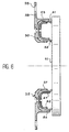
- FIG. 6 shows a radial type seal, according to the invention. It is applied here against the radial surface 11 of a rotating part, such as a plateau or the end surface of a large tree width. It also includes a flexible ribbon 53 in U shape maintained by an inner ring 50 and a outer ring 55. These two rings 50 and 55 have ends 56, 57, 61 and 62 of different lengths two by two for the same reasons as those mentioned for the axial seal. A fixing hole 59 is provided on a branch 58 to fix the joint.
- the essential advantages of the brush seal according to the invention are that it can be radial, as described in Figures 4 and 5, but can be also radial, as described in Figure 6.
Abstract
Description
L'invention concerne l'étanchéité entre deux enceintes ou volumes soumis à des pressions différentes et localisés autour d'un axe ou d'un arbre tournant. Elle concerne, en particulier, les turbomachines aéronautiques qui utilisent très fréquemment le type de joint d'étanchéité, appelé joint à brosse.The invention relates to sealing between two enclosures or volumes under pressure different and located around an axis or a tree turning. It concerns, in particular, aeronautical turbomachinery which use very frequently the type of seal, called a seal brush.
Les joints à brosse se présentent sous la forme de faisceaux de fils, fibres ou brins qui peuvent être métalliques, organiques ou synthétiques. Le choix du matériau est dicté par les conditions d'environnement et de fonctionnement du joint à brosse, c'est-à-dire par la nature des fluides à étancher, par les températures et les pressions régnant de part et d'autre du joint.The brush seals are located under the form of bundles of threads, fibers or strands which can be metallic, organic or synthetic. The choice of material is dictated by the conditions environment and operation of the brush seal, that is to say by the nature of the fluids to be sealed, by temperatures and pressures prevailing on both sides and on the other side of the joint.
En référence à la figure 1, un de ces types
de joints permet d'isoler deux volumes ou deux
enceintes A et B entourant un arbre rotatif 1. Le
faisceau de fils 2 est, de préférence, disposé
radialement par rapport à cet arbre rotatif 1 et son
extrémité 2E touche la surface extérieure de l'arbre
rotatif 1. Le faisceau de fils 2 est monté dans un
support fixe 3 qui constitue le support du joint. En
considérant le sens du flux d'air circulant à travers
le joint et symbolisé par la flèche F, on utilise, de
préférence, une bague amont 5 placée en amont du
faisceau de fils 2 et positionnée au moyen d'une bague
de fixation 7, fixée elle-même dans le support de joint
3. On utilise également une bague aval 6 fixée en aval
du faisceau de fils 2 et placée en appui contre une
nervure 4 du support de joint 3. On remarque que la
bague aval 6 a un diamètre intérieur plus restreint que
la bague amont 5. En d'autres termes, la bague aval
supporte sur une longueur plus importante le faisceau
de fils 2 que la bague amont 5. L'extrémité 2E du
faisceau 2 bénéficie donc d'une certaine liberté,
surtout du côté amont, c'est-à-dire de la bague amont
2. On délimite ainsi deux régions bien séparées par le
joint et dans lesquelles il peut régner des pressions
différentes.With reference to Figure 1, one of these types
of joints allows to isolate two volumes or two
enclosures A and B surrounding a rotating
En référence à la figure 2, par la demande
de brevet français 2 607 893, on connaít un joint à
brosse comprenant plusieurs faisceaux et, en
particulier, trois dans le cas représenté. Les trois
faisceaux de fils 12 sont fixés perpendiculairement à
l'arbre rotatif 1, par rapport auquel ils doivent
isoler plusieurs régions, en particulier, les régions
amont A et aval B, placées de part et d'autre de cet
ensemble de trois faisceaux à fils 12. Ces faisceaux de
fils 12 sont maintenus par des bagues amont 15 et aval
16 et sont positionnés par rapport à un support de
joint 13 au moyen d'une nervure 14 de ce dernier.Referring to Figure 2, by request
French patent 2,607,893, there is a seal with
brush comprising several beams and, in
in particular, three in the case shown. The three
bundles of
La définition technologique de tous ces types de joints à brosse est bien connue. Par contre, la fabrication de ces joints à brosse n'est pas toujours simple et de bonne qualité. The technological definition of all these types of brush seals is well known. On the other hand, the manufacture of these brush seals is not always simple and of good quality.
Les joints à brosse peuvent également être disposés axialement, par exemple dans le cadre d'applications semi-statiques, ou bien pour équiper un joint axial asservi. Dans ce cas, la mise en oeuvre des techniques classiques utilisées dans la conception des joints radiaux métalliques est impossible.Brush seals can also be arranged axially, for example in the frame semi-static applications, or to equip a slave axial seal. In this case, the implementation of classical techniques used in the design of metal radial seals is impossible.
Le but de cette invention est de proposer une conception de joints à brosse axiaux à double barrière d'étanchéité, cette conception est également applicable aux joints radiaux, même si le montage du joint s'avère plus complexe.The purpose of this invention is to provide double axial brush seal design sealing barrier, this design is also applicable to radial seals, even if the mounting of the joint is more complex.
A cet effet, l'objet principal de l'invention est un joint à brosse à double contact, axial ou radial, pour assurer l'étanchéité entre deux enceintes soumises à des pressions différentes et situées autour d'un arbre, tournant ou fixe, comprenant :
- deux faisceaux d'étanchéité flexibles, parallèles entre eux, et dont l'extrémité de chacun est en contact avec la surface de l'arbre tournant ou fixe ; et
- un corps de maintien dans lequel sont fixés les deux faisceaux d'étanchéité flexible.
- two flexible sealing bundles, mutually parallel, and the end of each of which is in contact with the surface of the rotating or fixed shaft; and
- a holding body in which are fixed the two flexible sealing bundles.
Selon une caractéristique principale de l'invention, les deux faisceaux d'étanchéité flexibles sont constitués par un unique ruban flexible en forme de U dont la partie centrale est fixée dans le corps de maintien.According to a main characteristic of the invention, the two flexible sealing bundles consist of a single flexible shaped ribbon of U whose central part is fixed in the body of maintenance.
Dans sa réalisation préférentielle, le corps de maintien est formé de deux anneaux, un anneau intérieur et un anneau extérieur, tous deux en forme de U et s'imbriquant l'un dans l'autre.In its preferred embodiment, the holding body is formed by two rings, a ring inside and an outside ring, both shaped like U and overlapping each other.
De préférence, les branches des deux anneaux en forme de U ne sont pas de la même longueur, de sorte que l'extrémité de chaque faisceau d'étanchéité n'est en contact qu'avec un seul anneau.Preferably, the branches of the two U-shaped rings are not the same length, so the end of each beam seal is in contact with only one ring.
Dans le cas d'une application radiale, il est préférable d'utiliser un moyen détrompeur, lors du montage des deux anneaux pour monter ces deux derniers dans le bon sens.In the case of a radial application, it is better to use a polarizing means, when mounting the two rings to mount the latter two in the right direction.
L'invention et ses différentes caractéristiques techniques seront mieux comprises à la lecture de la description suivante, accompagnée de quelques figures représentant respectivement :
- figure 1, déjà décrite, en coupe, un premier type de joint à brosse selon l'art antérieur ;
- figure 2, déjà décrite, en coupe, un deuxième type de joint à brosse selon l'art antérieur ;
- figure 3, en coupe, une première réalisation, radiale, du joint à brosse selon l'invention ;
- figure 4, en coupe, un exemple de montage erroné à éviter, lors la réalisation du joint à brosse selon l'invention ;
- figure 5, une deuxième réalisation, radiale, du joint à brosse selon l'invention ; et
- figure 6, une troisième réalisation, axiale, du joint à brosse selon l'invention.
- Figure 1, already described, in section, a first type of brush seal according to the prior art;
- Figure 2, already described, in section, a second type of brush seal according to the prior art;
- Figure 3, in section, a first radial embodiment of the brush seal according to the invention;
- Figure 4, in section, an example of incorrect mounting to avoid, when making the brush seal according to the invention;
- Figure 5, a second radial embodiment of the brush seal according to the invention; and
- Figure 6, a third axial embodiment of the brush seal according to the invention.
En référence à la figure 3, on considère le
joint à brosse de l'invention, de type radial, selon
une première réalisation, monté autour d'un arbre
rotatif 1. Il est constitué de deux pièces principales
qui sont un anneau intérieur 20 et un anneau extérieur
25. Outre le fait que ces deux anneaux intérieur 20 et
extérieur 25 sont circulaires, c'est-à-dire qu'ils
entourent l'arbre rotatif 1, ils possèdent chacun une
section en forme de U. L'anneau intérieur 20 est placé
à l'intérieur de l'anneau extérieur 25. Les deux
branches 21 et 22 de l'anneau intérieur 20 sont de
longueurs différentes, de même que les deux branches 26
et 27 de l'anneau extérieur 25.Referring to Figure 3, consider the
brush seal of the invention, of radial type, according to
a first achievement, mounted around a
De plus, en considérant la flèche F dans
une turbomachine aéronautique, la branche amont 26 de
l'anneau extérieur 25 est plus longue que la branche
aval 27 de ce dernier. Inversement, la branche amont 21
de l'anneau intérieur 20 est plus petite que la branche
aval 22 de ce dernier. De ce fait, chacune des deux
extrémités 31 et 32 du ruban flexible 30 constituant
les deux faisceaux d'étanchéité du joint ne sont en
contact chacune qu'avec une seule paroi d'un anneau,
soit intérieur 20, soit extérieur 25. Ainsi,
l'extrémité amont 31 du ruban flexible 30 est en
contact avec l'extrémité amont 26 de l'anneau extérieur
25 et l'extrémité aval 32 du ruban flexible 30 est en
contact avec la surface externe de l'extrémité aval 22
de l'anneau intérieur 20. Chaque extrémité 31 et 32 du
ruban flexible 30 bénéficie donc d'une liberté de
mouvement relativement grande, notamment du côté aval,
dans cette réalisation. On note que les extrémités les
plus longues, c'est-à-dire l'extrémité amont 26 de
l'anneau extérieur et l'extrémité aval 22 de l'anneau
intérieur 20, sont relativement proches de la surface
externe de l'arbre rotatif 1 pour limiter la liberté de
mouvement des deux extrémités 31 et 32 du ruban
flexible du côté amont. En d'autres termes, les parties
longues ou branches longues 22 et 26 des anneaux
intérieur 20 et extérieur 25 sont placées en opposition
pour guider les poils ou les fibres constituant la
brosse du ruban flexible au plus près de la zone de
contact avec la surface de l'arbre rotatif.In addition, considering the arrow F in
an aeronautical turbomachine, the
L'anneau extérieur 25 est doté d'une
branche 28 munie elle-même d'un trou de fixation 29
destiné à fixer le joint dans la turbomachine qui doit
être équipée de ce joint à brosse. De même, on prévoit
des moyens de fixation entre les deux anneaux interne
20 et externe 25, notamment par des trous de fixation
23 et 24. On peut également prévoir que ces deux
anneaux intérieur 20 et extérieur 25 puissent être
fixés par soudure, par rivetage ou par emboítement.The
Les deux anneaux intérieur 20 et extérieur
25 doivent être munis d'un moyen détrompeur pour
détromper l'opérateur qui réalise le montage de
ceux-ci. En effet, lors d'un tel montage, une
manipulation hasardeuse pourrait situer du même côté du
joint les branches de même longueur des deux panneaux
intérieur 20 et extérieur 25, comme le montre la figure
4 sur laquelle l'anneau intérieur 25 a été inversé par
rapport au montage de la figure 3. Bien entendu, dans
ce cas, le joint à brosse serait beaucoup moins
performant, dès le début de son utilisation. Un tel
moyen détrompeur (ou de détrompage) pourrait être
constitué par un pion de centrage fixé sur l'un des
deux anneaux et une cavité correspondante fixée sur
l'autre anneau, ces deux éléments n'étant pas placés
dans le plan médian des deux anneaux intérieur 20 et
extérieur 25. On peut également envisager que la partie
centrale des deux anneaux intérieur 20 et extérieur 25
soit conique, pour ne permettre qu'un seul sens
possible de montage.The two inner 20 and
En référence à la figure 5, une deuxième
réalisation du joint à brosse selon l'invention, de
type radial, prévoit un montage de celui-ci légèrement
différent. En effet, on utilise dans ce cas un support
40 concentrique avec l'arbre rotatif 1. Il possède une
nervure de positionnement amont 41 contre laquelle est
placé l'anneau extérieur 25. Celui-ci est fixé du côté
aval par une bague élastique 42, de manière à se
positionner à sa place axiale par rapport à l'arbre
rotatif 1. Mise à part cette caractéristique de
montage, les caractéristiques et la constitution du
joint, c'est-à-dire le ruban flexible 30, l'anneau
interne 20 et l'anneau externe 25 peuvent être
identiques à ceux décrits à la figure 3.Referring to Figure 5, a second
realization of the brush seal according to the invention,
radial type, provides for mounting thereof slightly
different. Indeed, we use in this case a
La figure 6 montre un joint de type radial,
selon l'invention. Il est ici appliqué contre la
surface radiale 11 d'une pièce tournante, telle qu'un
plateau ou la surface d'extrémité d'un arbre de grande
largeur. Il comporte également un ruban flexible 53 en
forme de U maintenu par un anneau intérieur 50 et un
anneau extérieur 55. Ces deux anneaux 50 et 55 ont des
extrémités 56, 57, 61 et 62 de longueurs différentes
deux à deux pour les mêmes raisons que celles évoquées
pour le joint axial. Un trou de fixation 59 est prévu
sur une branche 58 pour fixer le joint. FIG. 6 shows a radial type seal,
according to the invention. It is applied here against the
radial surface 11 of a rotating part, such as a
plateau or the end surface of a large tree
width. It also includes a
Les avantages essentiels du joint à brosse selon l'invention sont que celui-ci peut être radial, comme décrit sur les figures 4 et 5, mais peut être également radial, comme décrit sur la figure 6.The essential advantages of the brush seal according to the invention are that it can be radial, as described in Figures 4 and 5, but can be also radial, as described in Figure 6.
Bien entendu, la fabrication et le montage de celui-ci sont simplifiés, notamment, en ce qui concerne le montage des anneaux intérieur et extérieur, surtout pour le joint de type axial.Of course, manufacturing and mounting of it are simplified, in particular, with regard to concerns the mounting of the interior and exterior rings, especially for the axial type seal.
Claims (4)
Applications Claiming Priority (2)
| Application Number | Priority Date | Filing Date | Title |
|---|---|---|---|
| FR9815572A FR2787165B1 (en) | 1998-12-10 | 1998-12-10 | DOUBLE CONTACT BRUSH SEAL |
| FR9815572 | 1998-12-10 |
Publications (2)
| Publication Number | Publication Date |
|---|---|
| EP1008787A1 true EP1008787A1 (en) | 2000-06-14 |
| EP1008787B1 EP1008787B1 (en) | 2004-03-24 |
Family
ID=9533799
Family Applications (1)
| Application Number | Title | Priority Date | Filing Date |
|---|---|---|---|
| EP99403084A Expired - Lifetime EP1008787B1 (en) | 1998-12-10 | 1999-12-09 | Double contact seal brush |
Country Status (6)
| Country | Link |
|---|---|
| US (1) | US6328311B1 (en) |
| EP (1) | EP1008787B1 (en) |
| JP (1) | JP2000186772A (en) |
| CA (1) | CA2291606C (en) |
| DE (1) | DE69915781T2 (en) |
| FR (1) | FR2787165B1 (en) |
Cited By (3)
| Publication number | Priority date | Publication date | Assignee | Title |
|---|---|---|---|---|
| EP1146266A3 (en) * | 2000-04-13 | 2003-05-07 | MTU Aero Engines GmbH | Brush seal |
| WO2010015439A1 (en) * | 2008-08-05 | 2010-02-11 | Robert Bosch Gmbh | Seal arrangement |
| CN102812209A (en) * | 2010-03-26 | 2012-12-05 | 斯奈克玛 | Sealing device for jet engine oil chamber |
Families Citing this family (12)
| Publication number | Priority date | Publication date | Assignee | Title |
|---|---|---|---|---|
| US20030160392A1 (en) * | 2002-02-12 | 2003-08-28 | Szymbor John A. | Bristle arrangement for brush seal, method and assembly for making same, and method of making brush seal |
| US6996885B2 (en) * | 2002-03-20 | 2006-02-14 | United Technologies Corporation | Method of making bristle arrangement for brush seal |
| US20030201608A1 (en) * | 2002-04-25 | 2003-10-30 | United Technologies Corporation | Brush seal with fewer parts |
| US7270333B2 (en) * | 2002-11-27 | 2007-09-18 | United Technologies Corporation | Brush seal with adjustable clearance |
| US6779799B2 (en) * | 2002-11-27 | 2004-08-24 | General Electric Company | Sealing apparatus for electrical generator ventilation system |
| DE10324709A1 (en) * | 2003-05-30 | 2004-12-16 | Mtu Aero Engines Gmbh | Brush seal for sealing relatively movable components against a pressure drop |
| US6887038B2 (en) * | 2003-09-02 | 2005-05-03 | General Electric Company | Methods and apparatus to facilitate sealing between rotating turbine shafts |
| US7334311B2 (en) * | 2004-11-03 | 2008-02-26 | United Technologies Corporation | Method of forming a nested can brush seal |
| US7226054B2 (en) * | 2004-12-14 | 2007-06-05 | United Technologies Corporation | Clamp lock brush seal assembly |
| US7694564B2 (en) * | 2007-05-21 | 2010-04-13 | Alstom Technology Ltd. | Boiler tube inspection probe with centering mechanism and method of operating the same |
| ES2345310B1 (en) * | 2008-01-31 | 2011-07-22 | Airbus Operations, S.L. | SEALED FOR LABELED UNIONS AND ITS USE. |
| US11619138B2 (en) * | 2021-04-30 | 2023-04-04 | Raytheon Technologies Corporation | Double brush seal assembly |
Citations (2)
| Publication number | Priority date | Publication date | Assignee | Title |
|---|---|---|---|---|
| EP0211275A2 (en) * | 1985-07-31 | 1987-02-25 | Mtu Motoren- Und Turbinen-Union MàNchen Gmbh | Method and apparatus for manufacturing brush seals |
| FR2607893A1 (en) * | 1986-12-06 | 1988-06-10 | Rolls Royce Plc | BRUSH JOINT |
Family Cites Families (4)
| Publication number | Priority date | Publication date | Assignee | Title |
|---|---|---|---|---|
| US885032A (en) * | 1907-06-24 | 1908-04-21 | Sebastian Ziani De Ferranti | Fluid packing. |
| DE3802653C2 (en) * | 1988-01-29 | 2000-06-29 | Mtu Muenchen Gmbh | Brush seal |
| US5114159A (en) * | 1991-08-05 | 1992-05-19 | United Technologies Corporation | Brush seal and damper |
| DE29600193U1 (en) * | 1996-01-08 | 1996-03-14 | Mtu Muenchen Gmbh | Brush seal with C-shaped clamping ring |
-
1998
- 1998-12-10 FR FR9815572A patent/FR2787165B1/en not_active Expired - Fee Related
-
1999
- 1999-11-29 JP JP11337186A patent/JP2000186772A/en active Pending
- 1999-12-01 CA CA002291606A patent/CA2291606C/en not_active Expired - Lifetime
- 1999-12-03 US US09/453,511 patent/US6328311B1/en not_active Expired - Lifetime
- 1999-12-09 EP EP99403084A patent/EP1008787B1/en not_active Expired - Lifetime
- 1999-12-09 DE DE69915781T patent/DE69915781T2/en not_active Expired - Lifetime
Patent Citations (2)
| Publication number | Priority date | Publication date | Assignee | Title |
|---|---|---|---|---|
| EP0211275A2 (en) * | 1985-07-31 | 1987-02-25 | Mtu Motoren- Und Turbinen-Union MàNchen Gmbh | Method and apparatus for manufacturing brush seals |
| FR2607893A1 (en) * | 1986-12-06 | 1988-06-10 | Rolls Royce Plc | BRUSH JOINT |
Cited By (5)
| Publication number | Priority date | Publication date | Assignee | Title |
|---|---|---|---|---|
| EP1146266A3 (en) * | 2000-04-13 | 2003-05-07 | MTU Aero Engines GmbH | Brush seal |
| US7445212B2 (en) | 2000-04-13 | 2008-11-04 | Mtu Aero Engines Gmbh | Brush seal |
| WO2010015439A1 (en) * | 2008-08-05 | 2010-02-11 | Robert Bosch Gmbh | Seal arrangement |
| CN102812209A (en) * | 2010-03-26 | 2012-12-05 | 斯奈克玛 | Sealing device for jet engine oil chamber |
| CN102812209B (en) * | 2010-03-26 | 2015-02-18 | 斯奈克玛 | Sealing device for jet engine oil chamber |
Also Published As
| Publication number | Publication date |
|---|---|
| JP2000186772A (en) | 2000-07-04 |
| DE69915781D1 (en) | 2004-04-29 |
| EP1008787B1 (en) | 2004-03-24 |
| FR2787165B1 (en) | 2001-01-12 |
| US6328311B1 (en) | 2001-12-11 |
| CA2291606A1 (en) | 2000-06-10 |
| CA2291606C (en) | 2008-02-05 |
| FR2787165A1 (en) | 2000-06-16 |
| DE69915781T2 (en) | 2005-02-10 |
Similar Documents
| Publication | Publication Date | Title |
|---|---|---|
| EP1008787B1 (en) | Double contact seal brush | |
| EP0003091B1 (en) | Sealing ring | |
| EP0382606B1 (en) | Closing ring for corrugated conduits | |
| EP0572312B1 (en) | Sealing arrangement between stator blade rows and a rotating rotor drum | |
| EP0182716A1 (en) | Tip-sealing shroud for a gas turbine | |
| FR2493461A1 (en) | BALL VALVE DEVICE | |
| FR2558211A1 (en) | GAS TURBINE COMPRISING A SELF-ALIGNING STATIC SEAL FOR THE BLADES OF THE STATOR OF THIS TURBINE | |
| CA2884556C (en) | Brush-type circular seal | |
| EP0376772A1 (en) | Movable pipe connection, especially for motor vehicle exhaust pipes | |
| EP3084140B1 (en) | Guide arm for elements having an elongated shape, in particular for a turbomachine | |
| FR2654268A1 (en) | CABLE ENTRY SEALING DEVICE IN A MULTICONTACT ALVEOLIC CONNECTOR ELEMENT. | |
| EP0723098B1 (en) | Ultra-soft seal with double cover jacket | |
| FR2703753A1 (en) | Quick-fit gland (stuffing box) | |
| FR2703105A1 (en) | Device for catalytic purification of the exhaust gases of an engine, especially of a motor vehicle | |
| EP2015016A1 (en) | Heat exchanger for heating tank | |
| FR3070460A1 (en) | DEVICE FOR DAMPING THE VIBRATION OF A FLEXIBLE OR INTEGRAL INSULATING CABLE INTO A CAVITY, CABLE THUS EQUIPPED AND METHOD OF MANUFACTURE | |
| EP3943814A1 (en) | Section of smoke duct of the type with two concentric tubes and manufacturing method thereof | |
| FR3002481A1 (en) | Molding device for infusion molding of hollow part i.e. hydroelectric blade, has mold parts for defining mold cavity of hollow part, where one of mold parts comprise channel for introducing liquid resin into mold cavity | |
| FR2591955A1 (en) | Support device for exhaust pipes of endothermic engines, especially intended to support the exhaust silencer of a vehicle | |
| FR2683289A1 (en) | Seal for a butterfly valve and butterfly valve provided with such a seal | |
| FR2678704A1 (en) | Device for supporting elongate objects | |
| FR2908936A1 (en) | Electrical equipment case for use in dry partition wall, has opening elliptical in shape such that horizontal diameter of opening is smaller than conduit's outer diameter, where conduit introduced in opening is retained at closed points | |
| FR3079074A1 (en) | ASSEMBLY SYSTEM WITHOUT SCREWS OF TWO HOLLOW WAVEGUIDE PORTIONS | |
| FR2559834A1 (en) | Turbine ring | |
| EP0479034A1 (en) | Positioning device of a fibre optical splice in a support |
Legal Events
| Date | Code | Title | Description |
|---|---|---|---|
| PUAI | Public reference made under article 153(3) epc to a published international application that has entered the european phase |
Free format text: ORIGINAL CODE: 0009012 |
|
| 17P | Request for examination filed |
Effective date: 19991220 |
|
| AK | Designated contracting states |
Kind code of ref document: A1 Designated state(s): DE FR GB |
|
| AX | Request for extension of the european patent |
Free format text: AL;LT;LV;MK;RO;SI |
|
| AKX | Designation fees paid |
Free format text: DE FR GB |
|
| GRAH | Despatch of communication of intention to grant a patent |
Free format text: ORIGINAL CODE: EPIDOS IGRA |
|
| GRAH | Despatch of communication of intention to grant a patent |
Free format text: ORIGINAL CODE: EPIDOS IGRA |
|
| RAP1 | Party data changed (applicant data changed or rights of an application transferred) |
Owner name: SNECMA MOTEURS |
|
| GRAA | (expected) grant |
Free format text: ORIGINAL CODE: 0009210 |
|
| AK | Designated contracting states |
Kind code of ref document: B1 Designated state(s): DE FR GB |
|
| REG | Reference to a national code |
Ref country code: GB Ref legal event code: FG4D Free format text: NOT ENGLISH |
|
| REF | Corresponds to: |
Ref document number: 69915781 Country of ref document: DE Date of ref document: 20040429 Kind code of ref document: P |
|
| GBT | Gb: translation of ep patent filed (gb section 77(6)(a)/1977) |
Effective date: 20040421 |
|
| PLBE | No opposition filed within time limit |
Free format text: ORIGINAL CODE: 0009261 |
|
| STAA | Information on the status of an ep patent application or granted ep patent |
Free format text: STATUS: NO OPPOSITION FILED WITHIN TIME LIMIT |
|
| 26N | No opposition filed |
Effective date: 20041228 |
|
| REG | Reference to a national code |
Ref country code: FR Ref legal event code: CD |
|
| REG | Reference to a national code |
Ref country code: FR Ref legal event code: PLFP Year of fee payment: 17 |
|
| REG | Reference to a national code |
Ref country code: FR Ref legal event code: PLFP Year of fee payment: 18 |
|
| REG | Reference to a national code |
Ref country code: FR Ref legal event code: PLFP Year of fee payment: 19 |
|
| REG | Reference to a national code |
Ref country code: FR Ref legal event code: CD Owner name: SAFRAN AIRCRAFT ENGINES Effective date: 20170719 |
|
| PGFP | Annual fee paid to national office [announced via postgrant information from national office to epo] |
Ref country code: DE Payment date: 20181126 Year of fee payment: 20 |
|
| PGFP | Annual fee paid to national office [announced via postgrant information from national office to epo] |
Ref country code: FR Payment date: 20181127 Year of fee payment: 20 Ref country code: GB Payment date: 20181127 Year of fee payment: 20 |
|
| REG | Reference to a national code |
Ref country code: DE Ref legal event code: R071 Ref document number: 69915781 Country of ref document: DE |
|
| REG | Reference to a national code |
Ref country code: GB Ref legal event code: PE20 Expiry date: 20191208 |
|
| PG25 | Lapsed in a contracting state [announced via postgrant information from national office to epo] |
Ref country code: GB Free format text: LAPSE BECAUSE OF EXPIRATION OF PROTECTION Effective date: 20191208 |