EP1007856B1 - Rotator device - Google Patents
Rotator device Download PDFInfo
- Publication number
- EP1007856B1 EP1007856B1 EP98934122A EP98934122A EP1007856B1 EP 1007856 B1 EP1007856 B1 EP 1007856B1 EP 98934122 A EP98934122 A EP 98934122A EP 98934122 A EP98934122 A EP 98934122A EP 1007856 B1 EP1007856 B1 EP 1007856B1
- Authority
- EP
- European Patent Office
- Prior art keywords
- adjustable
- rotary actuator
- rotation stop
- housing
- rotation
- Prior art date
- Legal status (The legal status is an assumption and is not a legal conclusion. Google has not performed a legal analysis and makes no representation as to the accuracy of the status listed.)
- Expired - Lifetime
Links
- 238000006073 displacement reaction Methods 0.000 description 4
- 238000004519 manufacturing process Methods 0.000 description 2
- 239000000463 material Substances 0.000 description 2
- 229910000838 Al alloy Inorganic materials 0.000 description 1
- 239000002131 composite material Substances 0.000 description 1
- 230000001419 dependent effect Effects 0.000 description 1
- 238000004512 die casting Methods 0.000 description 1
Images

Classifications
-
- F—MECHANICAL ENGINEERING; LIGHTING; HEATING; WEAPONS; BLASTING
- F15—FLUID-PRESSURE ACTUATORS; HYDRAULICS OR PNEUMATICS IN GENERAL
- F15B—SYSTEMS ACTING BY MEANS OF FLUIDS IN GENERAL; FLUID-PRESSURE ACTUATORS, e.g. SERVOMOTORS; DETAILS OF FLUID-PRESSURE SYSTEMS, NOT OTHERWISE PROVIDED FOR
- F15B15/00—Fluid-actuated devices for displacing a member from one position to another; Gearing associated therewith
- F15B15/08—Characterised by the construction of the motor unit
- F15B15/12—Characterised by the construction of the motor unit of the oscillating-vane or curved-cylinder type
-
- F—MECHANICAL ENGINEERING; LIGHTING; HEATING; WEAPONS; BLASTING
- F15—FLUID-PRESSURE ACTUATORS; HYDRAULICS OR PNEUMATICS IN GENERAL
- F15B—SYSTEMS ACTING BY MEANS OF FLUIDS IN GENERAL; FLUID-PRESSURE ACTUATORS, e.g. SERVOMOTORS; DETAILS OF FLUID-PRESSURE SYSTEMS, NOT OTHERWISE PROVIDED FOR
- F15B15/00—Fluid-actuated devices for displacing a member from one position to another; Gearing associated therewith
- F15B15/20—Other details, e.g. assembly with regulating devices
- F15B15/24—Other details, e.g. assembly with regulating devices for restricting the stroke
Definitions
- This invention concerns a device in connection with a rotary actuator according to the preamble of claim 1.
- Such a device is previously known from for example DE-C2-39 43 716.
- the stop elements are adjustable in the rotational direction by friction means with screws.
- This device is relatively expensive and complicated to use. Besides it may occur that the stop elements are not sufficiently fastened and that they therefore may be displaced, for example after a certain time of use.
- a cover is provided for protection which must be removed in order to allow adjustment.
- the invention also provides possibility of providing the adjustable part with a setting scale, which is easily readable from the outside and which allows simple adjustment as well as control that a correct setting has been made.
- the fastening portion may be a unit which is separate from the rotary actuator housing but attachable thereto or simply an integral part of the rotary actuator housing which in that case provides the necessary connecting elements for allowing setting and fixing of the adjustable portion.
- the feature of claim 8 provides a very advantageous aspect of the invention meaning that a rotation position detector which is inserted into the receiving channel automatically follows the adjustment of the rotation stop housing and thereby the rotation stop element. This provides a considerable simplification compared to the prior art, wherein separate holders for rotation position detectors are provided which have to be set separately.
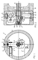
- the device 1 of Fig. 1 for limiting a rotational movement includes an adjustable portion of a rotation stop housing (item 2 is a section through a "second" portion of this housing).
- the portion 2 is essentially ring-shaped and adjustable in the rotational direction and fixable. Inwardly it provides a rotation stop 3 carrying a rotation stop element 4 which is adjustable by screwing in its axial direction, and which is intended to co-operate, limiting, with contact cushioning elements 5 on a rotary arm 9, which, as usual, is fastened to a shaft 10 of a rotary actuator.
- the figure further shows a channel 6, which in this case is comprised of a one-way bore, obliquely into the material of portion 2.
- This channel 6 is intended for receiving a rotation position detector, which is intended to detect a position of the rotary arm 9.
- a rotation position detector which is intended to detect a position of the rotary arm 9.
- magnetic detectors may be mentioned, which senses the presence of a magnet 8 being provided outmost on the rotary arm 9. 7 indicates a locking screw for fixing a detector being inserted into the channel 6.
- Fig. 1 also shows a rotation stop 3' having a rotation stop element 4', both elements belonging to a "first" portion 2' (see Fig. 2) of a device for limiting a rotational movement.
- the above described second portion 2 is shown in Fig. 2 as is also the first portion 2' of the device which is positioned axially displaced with respect to the second portion and which is generally cup-shaped and having a central hole 14 for a rotary actuator shaft bearing 13.
- the hole 14 further receives a reduced diameter portion 10' of a rotary actuator shaft 10, which is inside said bearing 13 and which further outmost is provided with an axial stop element, here a screw 12, between which element 12 and the bearing 13 a spring 11 is arranged.
- the spring 11 thus presses the bearing 13 and thereby the entire first portion 2' of the rotation stop housing and thus also its other portions 2 in the direction against the rotary actuator which is indicated with thin lines and is indicated with 18.
- a fixing portion 17 is fastened to this rotary actuator housing 18 which portion 17 is a part of the rotation stop housing in this embodiment.
- a first toothing 15 having radially extending teeth which in the position shown in the Figure prevents relative rotation between the portions 2 and 2', is provided between the first portion 2' and the second portion 2 and in more detail between the axially directed edge surfaces of the cup 2' and the ring.
- This arrangement gives a very rigid locking which can not be obtained by the conventional friction lock arrangement.
- the locking is also automatic by the axial spring load between the parts. In order to prevent play, also after some use and thereby possible wear between the teeth, they may have a tapering cross-section a certain angle in the direction of the free ends of the teeth.
- the craftsman In order to set a desired rotational limitation in two directions, the craftsman firstly only has to grip the envelope surface of the second portion, pull this portion axially to the left in Fig. 3 so that the co-operating teeth of the second toothing are disengaged from each other. Hereby the rotation of the second portion is allowed (in particular together with the first portion) so that the desired rotation stop 3 may be set as desired. After having completed the adjustment, the second portion may again be engaged through the second toothing 16 with the fastening portion 17 with the aid of the force of the spring 11. Fine adjustment may be obtained by screw setting the associated rotation stop element 4 in Fig. 1.
- the envelope surface of the first portion 2' of the rotation stop housing is gripped, so that the co-operating teeth on the first toothing 15 are disengaged whereupon also the first portion 2' is adjustable in the rotational direction to a desired position of the rotation stop 3'. Fine adjustment may be obtained with the aid of the element 4'.
- the invention thus provides very simple and efficient setting for the craftsman.
- Fig. 3 shows the device 1 for limiting a rotational movement being attached to the housing 18 of a rotary actuator. 19 indicates the cables to the rotation position detectors which are inserted into the respective channel 6 (see Fig. 1).
- the device according to the invention may thus include only one adjustable part, in cases where for example the rotary actuator itself is used for limiting the movement in the other direction. Further, the adjustment may be achieved otherwise than through an axial displacement and turning. It is thus within the scope of the invention to provide also such devices where the setting rotation may be stopped through other means than be above described axial displacement and co-operating teeth. For example locking pins, screws or other fastening elements may thus be used for this purpose.
- the fastening portion may be a separate part of the rotation stop housing or an integral part of a rotary actuator housing.
- the rotary actuator housing is provided with the necessary elements such as for example toothing, locking recesses or the like for co-operation with the respective adjustable portion of the rotation stop housing.
- the invention provides a cost-effective solution which among other things depends on the parts of the rotation stop housing with integral rotation stop being easily manufactured and easily mounted.
- the invention also allows the different parts to be manufactured through rational production methods whereby for example die-casting in an aluminium alloy or possibly forming in a plastic material or in a plastic composite are contemplated.
Landscapes
- Engineering & Computer Science (AREA)
- Physics & Mathematics (AREA)
- Fluid Mechanics (AREA)
- Mechanical Engineering (AREA)
- General Engineering & Computer Science (AREA)
- Actuator (AREA)
- Fluid-Damping Devices (AREA)
- Chairs For Special Purposes, Such As Reclining Chairs (AREA)
- Pivots And Pivotal Connections (AREA)
Description
Claims (11)
- Device (1) in connection with a rotary actuator for limiting a rotational movement of the rotary actuator shaft (10) and including at least one rotation stop element (3,3'), which is adjustable in the rotation direction and fixable and is intended to cooperate in a limiting manner with a rotary arm (9) fastened to the shaft of the rotary actuator and is housed inside a rotation stop housing (2,2') covering said at least one rotation stop element and said rotary arm (9),
characterized inthat the rotation stop housing comprises a first portion (2'), which is adjustable in the rotational direction and fixable with respect to the rotary actuator housing,that the rotation stop element (3',4') is rigidly connected to said first adjustable portion (2') of the rotation stop housing, andthat said first portion (2') is adjustable with respect to a fastening portion (17), which is a part being fixable to the rotary actuator housing or an integral part of the rotary actuator housing. - Device according to claim 1, characterized in that the rotary stop housing is also provided with a second adjustable portion (2) which is located axially displaced with respect to said first portion (2') and which is likewise adjustable in the rotational direction and fixable with respect to the rotary actuator housing and to which a second rotation stop element (3,4) is fastened.
- Device according to any of the claim 1 - 2, characterized in that the first portion is provided with means (11,12,13) for allowing a rotatable connection to the shaft (10) of the rotary actuator.
- Device according to claim 3, characterized in that said means (11-13) for allowing rotatable connection also allows relative axial movement between the respective adjustable portion (2,2') and said shaft (10) and thereby the fastening portion, whereby, in a first axial position of the respective adjustable portion, it is rotationally locked to the fastening portion, and in a second axial position, it is free for rotation with respect to the fastening portion (17).
- Device according to claim 4, characterized in that said relative axial movement is allowed against the action of a spring (11).
- Device according to any of the previous claims, characterized in that the respective adjustable portion (2,2') is fixable with respect to the fastening portion (17) through axially projecting fixing elements (15,16).
- Device according to claim 6, characterized in that said fixing elements are comprised of radially extending teeth (15,16).
- Device according to any of the previous claims, characterized in that each adjustable portion is provided with a channel (6) for a rotation position detector which is intended to detect the rotational position of the rotary arm (9), which is fastened to the rotary actuator shaft.
- Device according to claim 8, characterized in that each rotation stop element (4,4') is adjustable with respect to the respective adjustable portion (2,2').
- Device according to claim 9, characterized in that each rotation stop element (4,4') is adjustable by screwing.
- Rotary actuator, characterized in that it includes a device according to the any of the claims 1 - 10.
Applications Claiming Priority (3)
| Application Number | Priority Date | Filing Date | Title |
|---|---|---|---|
| SE9703172 | 1997-09-03 | ||
| SE9703172A SE510354C2 (en) | 1997-09-03 | 1997-09-03 | Device for rotary actuator and rotary actuator with such device |
| PCT/SE1998/001409 WO1999014506A1 (en) | 1997-09-03 | 1998-07-23 | Rotator device |
Publications (2)
| Publication Number | Publication Date |
|---|---|
| EP1007856A1 EP1007856A1 (en) | 2000-06-14 |
| EP1007856B1 true EP1007856B1 (en) | 2003-06-11 |
Family
ID=20408125
Family Applications (1)
| Application Number | Title | Priority Date | Filing Date |
|---|---|---|---|
| EP98934122A Expired - Lifetime EP1007856B1 (en) | 1997-09-03 | 1998-07-23 | Rotator device |
Country Status (5)
| Country | Link |
|---|---|
| EP (1) | EP1007856B1 (en) |
| JP (1) | JP2001516855A (en) |
| DE (1) | DE69815535T2 (en) |
| SE (1) | SE510354C2 (en) |
| WO (1) | WO1999014506A1 (en) |
Families Citing this family (2)
| Publication number | Priority date | Publication date | Assignee | Title |
|---|---|---|---|---|
| DE202006005174U1 (en) * | 2006-03-31 | 2006-06-22 | Festo Ag & Co | Fluid operated rotary actuator |
| JP7856293B2 (en) * | 2022-04-11 | 2026-05-11 | 株式会社アイエイアイ | Rotary actuator |
Family Cites Families (1)
| Publication number | Priority date | Publication date | Assignee | Title |
|---|---|---|---|---|
| DE3943716C2 (en) * | 1989-12-14 | 1995-01-05 | Festo Kg | Motor of oscillating-piston type |
-
1997
- 1997-09-03 SE SE9703172A patent/SE510354C2/en not_active IP Right Cessation
-
1998
- 1998-07-23 JP JP2000512014A patent/JP2001516855A/en active Pending
- 1998-07-23 DE DE69815535T patent/DE69815535T2/en not_active Expired - Fee Related
- 1998-07-23 EP EP98934122A patent/EP1007856B1/en not_active Expired - Lifetime
- 1998-07-23 WO PCT/SE1998/001409 patent/WO1999014506A1/en not_active Ceased
Also Published As
| Publication number | Publication date |
|---|---|
| EP1007856A1 (en) | 2000-06-14 |
| WO1999014506A1 (en) | 1999-03-25 |
| DE69815535T2 (en) | 2004-05-13 |
| SE9703172L (en) | 1999-03-04 |
| SE510354C2 (en) | 1999-05-17 |
| SE9703172D0 (en) | 1997-09-03 |
| DE69815535D1 (en) | 2003-07-17 |
| JP2001516855A (en) | 2001-10-02 |
Similar Documents
| Publication | Publication Date | Title |
|---|---|---|
| US7204351B2 (en) | Brake gear for a disc brake | |
| EP3566913B1 (en) | Seatbelt retractor | |
| TW523480B (en) | Integrated rotation-handle-switch | |
| RU2609842C2 (en) | Linings wear control device for disc brake | |
| EP0919747A3 (en) | Device for restricting the amount of rotation and webbing retractor using such a device | |
| CA2238849A1 (en) | Recliner apparatus | |
| JPH1044083A (en) | Robot rotary joint stopper | |
| EP3334888B1 (en) | Passage barrier system | |
| CA2048180A1 (en) | Key and rotary lock cylinder fro a safety lock | |
| EP1340571A3 (en) | Chuck with gripping mechanism stop | |
| US6964209B2 (en) | Sensor mount attachment device | |
| SE505278C2 (en) | Theft protection for shoes | |
| EP3300835A1 (en) | Accessory clamp and spindle lock mechanism for power tool lock | |
| EP0717166A1 (en) | Device for supporting and controlling a roller blind | |
| US5957628A (en) | Face milling cutter or angular milling cutter | |
| EP1007856A1 (en) | Rotator device | |
| US4402625A (en) | Apparatus for connection and disconnection of a hub to and from an internally threaded shaft | |
| GB2333979A (en) | Drilling chuck | |
| EP0735347B1 (en) | Rotational position detector device for rotary actuator | |
| GB2367513A (en) | Drill chuck | |
| CA2002128C (en) | Retaining system | |
| GB2063398A (en) | Spot-type disc brake including pad-wear compensator | |
| CZ302597A3 (en) | Removable hub for mounting a rotary mechanism onto a driving shaft and the rotary mechanism equipped by such removable hub | |
| SE514590C2 (en) | Milling Tools | |
| EP1066920A3 (en) | Air tool provided with safety device |
Legal Events
| Date | Code | Title | Description |
|---|---|---|---|
| PUAI | Public reference made under article 153(3) epc to a published international application that has entered the european phase |
Free format text: ORIGINAL CODE: 0009012 |
|
| 17P | Request for examination filed |
Effective date: 20000124 |
|
| AK | Designated contracting states |
Kind code of ref document: A1 Designated state(s): DE FR GB IT |
|
| GRAH | Despatch of communication of intention to grant a patent |
Free format text: ORIGINAL CODE: EPIDOS IGRA |
|
| GRAH | Despatch of communication of intention to grant a patent |
Free format text: ORIGINAL CODE: EPIDOS IGRA |
|
| GRAA | (expected) grant |
Free format text: ORIGINAL CODE: 0009210 |
|
| AK | Designated contracting states |
Designated state(s): DE FR GB IT |
|
| PG25 | Lapsed in a contracting state [announced via postgrant information from national office to epo] |
Ref country code: IT Free format text: LAPSE BECAUSE OF FAILURE TO SUBMIT A TRANSLATION OF THE DESCRIPTION OR TO PAY THE FEE WITHIN THE PRESCRIBED TIME-LIMIT;WARNING: LAPSES OF ITALIAN PATENTS WITH EFFECTIVE DATE BEFORE 2007 MAY HAVE OCCURRED AT ANY TIME BEFORE 2007. THE CORRECT EFFECTIVE DATE MAY BE DIFFERENT FROM THE ONE RECORDED. Effective date: 20030611 Ref country code: FR Free format text: LAPSE BECAUSE OF FAILURE TO SUBMIT A TRANSLATION OF THE DESCRIPTION OR TO PAY THE FEE WITHIN THE PRESCRIBED TIME-LIMIT Effective date: 20030611 |
|
| REG | Reference to a national code |
Ref country code: GB Ref legal event code: FG4D |
|
| REF | Corresponds to: |
Ref document number: 69815535 Country of ref document: DE Date of ref document: 20030717 Kind code of ref document: P |
|
| PG25 | Lapsed in a contracting state [announced via postgrant information from national office to epo] |
Ref country code: GB Free format text: LAPSE BECAUSE OF NON-PAYMENT OF DUE FEES Effective date: 20030911 |
|
| PLBE | No opposition filed within time limit |
Free format text: ORIGINAL CODE: 0009261 |
|
| STAA | Information on the status of an ep patent application or granted ep patent |
Free format text: STATUS: NO OPPOSITION FILED WITHIN TIME LIMIT |
|
| GBPC | Gb: european patent ceased through non-payment of renewal fee |
Effective date: 20030911 |
|
| 26N | No opposition filed |
Effective date: 20040312 |
|
| EN | Fr: translation not filed | ||
| PGFP | Annual fee paid to national office [announced via postgrant information from national office to epo] |
Ref country code: DE Payment date: 20050714 Year of fee payment: 8 |
|
| PG25 | Lapsed in a contracting state [announced via postgrant information from national office to epo] |
Ref country code: DE Free format text: LAPSE BECAUSE OF NON-PAYMENT OF DUE FEES Effective date: 20070201 |