EP1007854B1 - Pulsation damper - Google Patents
Pulsation damper Download PDFInfo
- Publication number
- EP1007854B1 EP1007854B1 EP98941901A EP98941901A EP1007854B1 EP 1007854 B1 EP1007854 B1 EP 1007854B1 EP 98941901 A EP98941901 A EP 98941901A EP 98941901 A EP98941901 A EP 98941901A EP 1007854 B1 EP1007854 B1 EP 1007854B1
- Authority
- EP
- European Patent Office
- Prior art keywords
- openings
- pulsation damper
- outlet
- inlet
- diffuser
- Prior art date
- Legal status (The legal status is an assumption and is not a legal conclusion. Google has not performed a legal analysis and makes no representation as to the accuracy of the status listed.)
- Expired - Lifetime
Links
Images
Classifications
-
- F—MECHANICAL ENGINEERING; LIGHTING; HEATING; WEAPONS; BLASTING
- F04—POSITIVE - DISPLACEMENT MACHINES FOR LIQUIDS; PUMPS FOR LIQUIDS OR ELASTIC FLUIDS
- F04C—ROTARY-PISTON, OR OSCILLATING-PISTON, POSITIVE-DISPLACEMENT MACHINES FOR LIQUIDS; ROTARY-PISTON, OR OSCILLATING-PISTON, POSITIVE-DISPLACEMENT PUMPS
- F04C29/00—Component parts, details or accessories of pumps or pumping installations, not provided for in groups F04C18/00 - F04C28/00
- F04C29/06—Silencing
- F04C29/063—Sound absorbing materials
-
- F—MECHANICAL ENGINEERING; LIGHTING; HEATING; WEAPONS; BLASTING
- F01—MACHINES OR ENGINES IN GENERAL; ENGINE PLANTS IN GENERAL; STEAM ENGINES
- F01N—GAS-FLOW SILENCERS OR EXHAUST APPARATUS FOR MACHINES OR ENGINES IN GENERAL; GAS-FLOW SILENCERS OR EXHAUST APPARATUS FOR INTERNAL COMBUSTION ENGINES
- F01N1/00—Silencing apparatus characterised by method of silencing
- F01N1/08—Silencing apparatus characterised by method of silencing by reducing exhaust energy by throttling or whirling
- F01N1/10—Silencing apparatus characterised by method of silencing by reducing exhaust energy by throttling or whirling in combination with sound-absorbing materials
-
- F—MECHANICAL ENGINEERING; LIGHTING; HEATING; WEAPONS; BLASTING
- F16—ENGINEERING ELEMENTS AND UNITS; GENERAL MEASURES FOR PRODUCING AND MAINTAINING EFFECTIVE FUNCTIONING OF MACHINES OR INSTALLATIONS; THERMAL INSULATION IN GENERAL
- F16L—PIPES; JOINTS OR FITTINGS FOR PIPES; SUPPORTS FOR PIPES, CABLES OR PROTECTIVE TUBING; MEANS FOR THERMAL INSULATION IN GENERAL
- F16L55/00—Devices or appurtenances for use in, or in connection with, pipes or pipe systems
- F16L55/04—Devices damping pulsations or vibrations in fluids
-
- F—MECHANICAL ENGINEERING; LIGHTING; HEATING; WEAPONS; BLASTING
- F01—MACHINES OR ENGINES IN GENERAL; ENGINE PLANTS IN GENERAL; STEAM ENGINES
- F01N—GAS-FLOW SILENCERS OR EXHAUST APPARATUS FOR MACHINES OR ENGINES IN GENERAL; GAS-FLOW SILENCERS OR EXHAUST APPARATUS FOR INTERNAL COMBUSTION ENGINES
- F01N2260/00—Exhaust treating devices having provisions not otherwise provided for
- F01N2260/18—Exhaust treating devices having provisions not otherwise provided for for improving rigidity, e.g. by wings, ribs
-
- F—MECHANICAL ENGINEERING; LIGHTING; HEATING; WEAPONS; BLASTING
- F01—MACHINES OR ENGINES IN GENERAL; ENGINE PLANTS IN GENERAL; STEAM ENGINES
- F01N—GAS-FLOW SILENCERS OR EXHAUST APPARATUS FOR MACHINES OR ENGINES IN GENERAL; GAS-FLOW SILENCERS OR EXHAUST APPARATUS FOR INTERNAL COMBUSTION ENGINES
- F01N2490/00—Structure, disposition or shape of gas-chambers
- F01N2490/02—Two or more expansion chambers in series connected by means of tubes
- F01N2490/04—Two or more expansion chambers in series connected by means of tubes the gases flowing longitudinally from inlet to outlet only in one direction
Definitions
- the present invention relates to a pulsation damper according to the preamble of claim 1.
- a damper of this kind is known from US-A-5563382 and serves to damp gas pulses with a frequency of less than 100 Hz and preferably between 10 and 20 Hz. In doing so. it is necessary to satisfy the requirements of various standards, of which the API standard is the most important. This standard prescribes that the peak-to-peak pulsation with respect to the average absolute pressure is never more than 2% of the average sound level.
- the object of the present invention is to provide a pulsation damper which has improved damping characteristics without its design being complicated to any significant extent.
- Another object of the invention is to increase the service life of diffuser pipes of this nature.
- One way of damping sound waves is to arrange a diffuser either in the inlet or in the outlet.
- a diffuser of this nature comprises a pipe-like part which is provided with a perforation.
- the total surface area of the free passage of the perforations is at least equal to the total inlet or outlet surface. Owing to the relatively small openings, perforations of this kind are particularly exposed to corrosive conditions. In practice, it has been found that, in particular, perforated parts of pipes rupture under the pressure wave load after a relatively short time.
- the perforated part of the diffuser is reinforced by means of reinforcement bodies extending along the circumference. These are preferably realized by starting from a pipe and forming windows in this pipe with large openings by, for example, cutting, while reinforcement bodies of this nature extending along the circumference remain in place between the openings. Naturally, in a design of this nature longitudinal bodies are present in order to provide sufficient strength in the axial direction. In a design of this nature, the perforation can be realized in a particularly simple manner by arranging perforated plates on the openings or windows obtained in this way. Depending on the design of the diffuser, perforated plates of this nature will be arranged on the inside or outside of the pipes. If the diffuser is an inlet diffuser, the gas pressure from the inside of the pipe will act outwards, so that it is preferable to arrange a perforated plate of this nature on the inside. For an outlet diffuser, this situation is precisely reversed.
- both an inlet diffuser and an outlet diffuser are provided.
- the damping members described above may comprise any structure known in the prior art.
- a so-called multipipe damper is used.
- This comprises a pipe-supporting structure which is completely closed, through which pipe-supporting structure there extend a number of pipes which connect the two closed-off chambers in the vessel to one another.
- this pipe-supporting structure comprises two curved plate parts which lie at a distance from one another. In this case, the curvature is always directed away from the adjoining plate part in question, so that a "hamburger-like" structure is produced.
- a further sound-absorbing material such as bituminous material, may be arranged between these two plates.
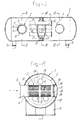
- Fig. 1 shows a pulsation damper. It consists of a vessel 1 which may have any size known in the prior art for the purpose of damping low-frequency vibrations.
- the inlet 2 of this vessel is connected, optionally directly and in a manner which is not shown in more detail, to a compressor of the Roots blower type.
- the outlet 3 is connected, in a manner which is not shown in more detail, to further devices.
- a so-called multipipe damper 4 is arranged between the inlet 2 and the outlet 3.
- both the inlet and the outlet comprise a diffuser.
- the inlet is provided with an inlet flange 5 to which a pipe member 6 is connected.
- a receiving ring 10 is welded to the opposite side of the vessel. The free open end of the pipe member 6 projects into this ring.
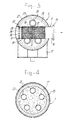
- the pipe member 6 is provided with comparatively large openings 12, for example by being cut, circumferential bodies 7 and longitudinal bodies 8 being delimited between the openings. These bodies consist of the same material as the pipe member.
- a perforated plate is arranged in the pipe member at the location of these openings 12.
- This plate is denoted by 9.
- the surface of the openings 12 comprises preferably 50-70% of the circumferential surface area of the pipe.
- the perforated plate 9 can be attached to the pipe member 6 by means of welding. It can be seen from Figure 1 that the perforated plate 9, like the opening 12, extends only on the "left-hand side" of the pipe body 6. This means that gas which flows in is initially directed to the left, so that the distance which it has to cover in order to reach the outlet 3 is as great as possible.
- the outlet diffuser arranged in outlet 3 is designed in a corresponding manner to the inlet diffuser. It comprises an outlet flange 15, pipe member 16 provided with circumferential bodies 17 and longitudinal bodies 18. Here, owing to the direction of flow of the gas, the perforated plate 19 is attached to the outside of the pipe member. The pipe member 16 is again attached with the aid of a receiving ring 20.
- the outlet diffuser shown here is not provided with the components 28-30, but it should be understood that these components may be arranged therein.
- the vessel contains silencing members comprising two curved tube plates 24, 25 which are connected, via supports 22, to the circumference of the vessel. Apart from a water drain 23, both the plates are completely sealed. Open pipes 26 extend through these tube plates. It can be seen from the drawings that the plates 24 and 25 are of convex design. A filling 27 may be situated between these tube plates. This filling then preferably consists of a sound-absorbing material and is obtained, for example, by filling with bituminous material.
- tube plates 24 and 25 are shown at a certain distance apart in the present exemplary embodiment, it should be understood that they may also be attached to one another.
Landscapes
- Engineering & Computer Science (AREA)
- General Engineering & Computer Science (AREA)
- Mechanical Engineering (AREA)
- Chemical & Material Sciences (AREA)
- Combustion & Propulsion (AREA)
- Pipe Accessories (AREA)
- Exhaust Silencers (AREA)
- Aeration Devices For Treatment Of Activated Polluted Sludge (AREA)
- Structures Of Non-Positive Displacement Pumps (AREA)
- Surgical Instruments (AREA)
- Devices For Conveying Motion By Means Of Endless Flexible Members (AREA)
Abstract
Description
- Fig. 1
- shows a side view, partially in section, of the pulsation damper according to the invention;
- Fig. 2
- shows a cross-section on line II-II in Fig. 1;
- Fig. 3
- shows a cross-section on line III-III in Fig. 1;
- Fig. 4
- shows a cross-section on line IV-IV in Fig. 1, and
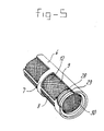
- Fig. 5
- shows a detail of the inlet of the vessel.
Claims (9)
- Pulsation damper for damping low-frequency gas pulses, comprising a vessel (1), having an inlet (2), outlet (3) and silencing members (4) which are arranged in the vessel, at least said inlet or outlet being provided with a diffuser comprising a pipe-like part (6, 16) which is provided with first openings, characterized in that, said pipe-like part comprises a member, which is provided with a number of second openings (12) and is delimited by reinforcement bodies (7,17) which extend around the circumference, at least one of said second openings (12) being covered by a plate (9,19) which plate is provided with said first openings being smaller than said second openings(12).
- Pulsation damper according to claim 1, in which the pipe-like part is provided, in the region of said perforation, with longitudinal reinforcement bodies (8, 18) which extend in the axial direction thereof.
- Pulsation damper according to Claim 2, in which said plate is arranged upstream, in the direction of flow of the gas, of the reinforcement bodies.
- Pulsation damper according to one of the preceding claims, in which said inlet diffuser or outlet diffuser has a part facing towards the outlet or inlet and a part facing away from said outlet or inlet, only the latter part being provided with said first openings.
- Pulsation damper comprising an inlet diffuser and outlet diffuser according to one of Claims 1-4.
- Pulsation damper according to one of the preceding claims, in which a chamber is delimited between the closed end of the pipe and said first openings, and in which a perforated plate (30) is arranged between said chamber and the rest of the pipe.
- Pulsation damper according to one of the preceding claims, in which said damping members comprise a structure which closes off the vessel essentially completely over a cross-section, a number of pipes (26), which realize the connection on either side of said cross-section, extending through said structure, which closure structure comprises two plates (24, 25) which lie at a distance from one another in the longitudinal extent of said pipes.
- Pulsation damper according to Claim 7, in which at least one of said plates is curved with a curvature directed away from the other said plate.
- Pulsation damper according to Claim 7 and/or 8, in which the chamber between said plates is filled with sound-absorbing material (27).
Applications Claiming Priority (3)
| Application Number | Priority Date | Filing Date | Title |
|---|---|---|---|
| NL1006892 | 1997-08-29 | ||
| NL1006892A NL1006892C2 (en) | 1997-08-29 | 1997-08-29 | Pulsation damper. |
| PCT/NL1998/000486 WO1999011938A1 (en) | 1997-08-29 | 1998-08-28 | Pulsation damper |
Publications (2)
| Publication Number | Publication Date |
|---|---|
| EP1007854A1 EP1007854A1 (en) | 2000-06-14 |
| EP1007854B1 true EP1007854B1 (en) | 2003-10-01 |
Family
ID=19765577
Family Applications (1)
| Application Number | Title | Priority Date | Filing Date |
|---|---|---|---|
| EP98941901A Expired - Lifetime EP1007854B1 (en) | 1997-08-29 | 1998-08-28 | Pulsation damper |
Country Status (9)
| Country | Link |
|---|---|
| US (1) | US6302236B1 (en) |
| EP (1) | EP1007854B1 (en) |
| JP (1) | JP4422890B2 (en) |
| AT (1) | ATE251278T1 (en) |
| AU (1) | AU733424B2 (en) |
| CA (2) | CA2302030C (en) |
| DE (1) | DE69818687T2 (en) |
| NL (1) | NL1006892C2 (en) |
| WO (1) | WO1999011938A1 (en) |
Families Citing this family (8)
| Publication number | Priority date | Publication date | Assignee | Title |
|---|---|---|---|---|
| CN100520085C (en) * | 2004-06-15 | 2009-07-29 | 霍尼韦尔国际公司 | Acoustic damper integrated to a compressor housing |
| ES2355919T3 (en) * | 2005-05-31 | 2011-04-01 | Carrier Corporation | METHODS AND APPLIANCES TO REDUCE THE NOISE LEVEL PRODUCED BY AN OIL SEPARATOR. |
| ES2581731T3 (en) * | 2006-05-18 | 2016-09-07 | Aerzener Maschinenfabrik Gmbh | Dry running rotary plunger machine with reactive silencer |
| GB2480182B (en) * | 2009-03-23 | 2012-05-09 | Vortex Performance Exhausts Ltd | An improved exhaust filter |
| CN103244464A (en) * | 2013-04-28 | 2013-08-14 | 山东省章丘鼓风机股份有限公司 | Roots blower pipeline noise reduction device |
| DE102017107599A1 (en) | 2017-04-10 | 2018-10-11 | Gardner Denver Deutschland Gmbh | Pulsation silencer for compressors |
| DE102017107601B4 (en) | 2017-04-10 | 2019-11-07 | Gardner Denver Deutschland Gmbh | Method for controlling a screw compressor |
| DE102017107602B3 (en) | 2017-04-10 | 2018-09-20 | Gardner Denver Deutschland Gmbh | Compressor system with internal air-water cooling |
Family Cites Families (14)
| Publication number | Priority date | Publication date | Assignee | Title |
|---|---|---|---|---|
| JPS53665Y2 (en) * | 1973-08-23 | 1978-01-11 | ||
| US4011922A (en) * | 1975-07-18 | 1977-03-15 | Nelson Industries, Inc. | Muffler construction |
| US3957133A (en) * | 1975-09-10 | 1976-05-18 | Scovill Manufacturing Company | Muffler |
| JPS595135Y2 (en) * | 1979-04-06 | 1984-02-16 | 株式会社クボタ | Silencer |
| SU1507997A1 (en) * | 1987-02-20 | 1989-09-15 | Научно-Исследовательский Институт Общей Гигиены И Профессиональных Заболеваний Министерства Здравоохранения Армсср | Silencer |
| US5227593A (en) * | 1990-09-12 | 1993-07-13 | Suzuki Kabushiki Kaisha | Muffler assembly for engine |
| US5365025A (en) * | 1992-01-24 | 1994-11-15 | Tennessee Gas Pipeline Company | Low backpressure straight-through reactive and dissipative muffler |
| NL9200313A (en) * | 1992-02-19 | 1993-09-16 | Qe International B V | DAMPER FOR COMPRESSED AIR. |
| JPH0714119U (en) * | 1993-08-12 | 1995-03-10 | カルソニック株式会社 | Tail pipe silencer |
| JP2883010B2 (en) * | 1994-10-17 | 1999-04-19 | 科学技術庁航空宇宙技術研究所長 | Silencer tower for low frequency noise |
| JP2682574B2 (en) * | 1994-10-17 | 1997-11-26 | 科学技術庁航空宇宙技術研究所長 | Resonant silencer for low frequency noise |
| US6082487A (en) * | 1998-02-13 | 2000-07-04 | Donaldson Company, Inc. | Mufflers for use with engine retarders; and methods |
| US6155379A (en) * | 1998-07-08 | 2000-12-05 | Nsu Corporation | Silencing member for mufflers and method of manufacturing the silencing member |
| US6109387A (en) * | 1999-07-19 | 2000-08-29 | Boretti; Napoleon P. | Silencer for gas discharge devices |
-
1997
- 1997-08-29 NL NL1006892A patent/NL1006892C2/en not_active IP Right Cessation
-
1998
- 1998-08-28 DE DE69818687T patent/DE69818687T2/en not_active Expired - Lifetime
- 1998-08-28 AU AU90058/98A patent/AU733424B2/en not_active Ceased
- 1998-08-28 CA CA002302030A patent/CA2302030C/en not_active Expired - Fee Related
- 1998-08-28 AT AT98941901T patent/ATE251278T1/en active
- 1998-08-28 US US09/486,478 patent/US6302236B1/en not_active Expired - Lifetime
- 1998-08-28 EP EP98941901A patent/EP1007854B1/en not_active Expired - Lifetime
- 1998-08-28 JP JP2000508914A patent/JP4422890B2/en not_active Expired - Fee Related
- 1998-08-28 WO PCT/NL1998/000486 patent/WO1999011938A1/en active IP Right Grant
- 1998-08-28 CA CA2629430A patent/CA2629430C/en not_active Expired - Fee Related
Also Published As
| Publication number | Publication date |
|---|---|
| EP1007854A1 (en) | 2000-06-14 |
| US6302236B1 (en) | 2001-10-16 |
| WO1999011938A1 (en) | 1999-03-11 |
| CA2302030A1 (en) | 1999-03-11 |
| JP4422890B2 (en) | 2010-02-24 |
| AU9005898A (en) | 1999-03-22 |
| JP2001515177A (en) | 2001-09-18 |
| CA2302030C (en) | 2009-01-06 |
| DE69818687T2 (en) | 2004-04-22 |
| CA2629430C (en) | 2011-07-12 |
| DE69818687D1 (en) | 2003-11-06 |
| CA2629430A1 (en) | 1999-03-11 |
| ATE251278T1 (en) | 2003-10-15 |
| NL1006892C2 (en) | 1999-03-02 |
| AU733424B2 (en) | 2001-05-17 |
Similar Documents
| Publication | Publication Date | Title |
|---|---|---|
| US4267899A (en) | Muffler assembly | |
| US4314621A (en) | Fluidborne noise attenuator | |
| US6968923B2 (en) | Reduced noise valve stack connection | |
| US4671380A (en) | Hydraulic noise attenuators | |
| US5859393A (en) | Reduced cost vent silencer | |
| EP1007854B1 (en) | Pulsation damper | |
| KR930016660A (en) | Exhaust Side Silencer of Compressor | |
| US5101930A (en) | Hydraulic elevator muffler | |
| US5677518A (en) | Device for deadening sound in pipelines | |
| AU672601B2 (en) | Silencer for compressed air | |
| KR830002109A (en) | Broadband pulsation attenuator | |
| EP1359366A1 (en) | Perforated pulsation dampener and dampening system | |
| CN212178231U (en) | Pipeline shock absorber | |
| KR200397669Y1 (en) | acoustic damper for gas pipeline | |
| JPH0633917A (en) | Liquid pressure reducing device | |
| EP0402423A1 (en) | Soundproofing wall element | |
| JPH08200585A (en) | Noise preventing structure for fluid control valve | |
| EP0025033B1 (en) | Hydraulic noise attenuator | |
| RU2199050C1 (en) | Device for dampening pressure fluctuations | |
| JPH0135031Y2 (en) | ||
| Kohmann et al. | Noise reduction in fluid filled pipes on ships by a new muffler | |
| RU2083910C1 (en) | Pressure stabilizer | |
| SU1765591A1 (en) | Noise suppression value | |
| KR100508164B1 (en) | Connecting apparatus for variable muffler | |
| JPS6249516B2 (en) |
Legal Events
| Date | Code | Title | Description |
|---|---|---|---|
| PUAI | Public reference made under article 153(3) epc to a published international application that has entered the european phase |
Free format text: ORIGINAL CODE: 0009012 |
|
| 17P | Request for examination filed |
Effective date: 20000218 |
|
| AK | Designated contracting states |
Kind code of ref document: A1 Designated state(s): AT BE DE FR GB IT NL |
|
| GRAH | Despatch of communication of intention to grant a patent |
Free format text: ORIGINAL CODE: EPIDOS IGRA |
|
| GRAH | Despatch of communication of intention to grant a patent |
Free format text: ORIGINAL CODE: EPIDOS IGRA |
|
| GRAA | (expected) grant |
Free format text: ORIGINAL CODE: 0009210 |
|
| AK | Designated contracting states |
Kind code of ref document: B1 Designated state(s): AT BE DE FR GB IT NL |
|
| REG | Reference to a national code |
Ref country code: GB Ref legal event code: FG4D |
|
| REF | Corresponds to: |
Ref document number: 69818687 Country of ref document: DE Date of ref document: 20031106 Kind code of ref document: P |
|
| ET | Fr: translation filed | ||
| PLBE | No opposition filed within time limit |
Free format text: ORIGINAL CODE: 0009261 |
|
| STAA | Information on the status of an ep patent application or granted ep patent |
Free format text: STATUS: NO OPPOSITION FILED WITHIN TIME LIMIT |
|
| 26N | No opposition filed |
Effective date: 20040702 |
|
| PGFP | Annual fee paid to national office [announced via postgrant information from national office to epo] |
Ref country code: NL Payment date: 20130521 Year of fee payment: 16 |
|
| PGFP | Annual fee paid to national office [announced via postgrant information from national office to epo] |
Ref country code: AT Payment date: 20130828 Year of fee payment: 16 |
|
| PGFP | Annual fee paid to national office [announced via postgrant information from national office to epo] |
Ref country code: FR Payment date: 20130830 Year of fee payment: 16 Ref country code: GB Payment date: 20130902 Year of fee payment: 16 |
|
| PGFP | Annual fee paid to national office [announced via postgrant information from national office to epo] |
Ref country code: IT Payment date: 20130822 Year of fee payment: 16 |
|
| PGFP | Annual fee paid to national office [announced via postgrant information from national office to epo] |
Ref country code: BE Payment date: 20130926 Year of fee payment: 16 Ref country code: DE Payment date: 20131031 Year of fee payment: 16 |
|
| REG | Reference to a national code |
Ref country code: DE Ref legal event code: R119 Ref document number: 69818687 Country of ref document: DE |
|
| REG | Reference to a national code |
Ref country code: NL Ref legal event code: V1 Effective date: 20150301 |
|
| REG | Reference to a national code |
Ref country code: AT Ref legal event code: MM01 Ref document number: 251278 Country of ref document: AT Kind code of ref document: T Effective date: 20140828 |
|
| GBPC | Gb: european patent ceased through non-payment of renewal fee |
Effective date: 20140828 |
|
| PG25 | Lapsed in a contracting state [announced via postgrant information from national office to epo] |
Ref country code: NL Free format text: LAPSE BECAUSE OF NON-PAYMENT OF DUE FEES Effective date: 20150301 Ref country code: BE Free format text: LAPSE BECAUSE OF NON-PAYMENT OF DUE FEES Effective date: 20140831 Ref country code: IT Free format text: LAPSE BECAUSE OF NON-PAYMENT OF DUE FEES Effective date: 20140828 |
|
| REG | Reference to a national code |
Ref country code: DE Ref legal event code: R119 Ref document number: 69818687 Country of ref document: DE Effective date: 20150303 |
|
| PG25 | Lapsed in a contracting state [announced via postgrant information from national office to epo] |
Ref country code: AT Free format text: LAPSE BECAUSE OF NON-PAYMENT OF DUE FEES Effective date: 20140828 |
|
| REG | Reference to a national code |
Ref country code: FR Ref legal event code: ST Effective date: 20150430 |
|
| PG25 | Lapsed in a contracting state [announced via postgrant information from national office to epo] |
Ref country code: GB Free format text: LAPSE BECAUSE OF NON-PAYMENT OF DUE FEES Effective date: 20140828 Ref country code: DE Free format text: LAPSE BECAUSE OF NON-PAYMENT OF DUE FEES Effective date: 20150303 |
|
| PG25 | Lapsed in a contracting state [announced via postgrant information from national office to epo] |
Ref country code: FR Free format text: LAPSE BECAUSE OF NON-PAYMENT OF DUE FEES Effective date: 20140901 |