EP1007824B1 - Method of fitting a valve seating ring and an apparatus therefor - Google Patents
Method of fitting a valve seating ring and an apparatus therefor Download PDFInfo
- Publication number
- EP1007824B1 EP1007824B1 EP97944003A EP97944003A EP1007824B1 EP 1007824 B1 EP1007824 B1 EP 1007824B1 EP 97944003 A EP97944003 A EP 97944003A EP 97944003 A EP97944003 A EP 97944003A EP 1007824 B1 EP1007824 B1 EP 1007824B1
- Authority
- EP
- European Patent Office
- Prior art keywords
- tool
- ring
- component
- valve seating
- weld
- Prior art date
- Legal status (The legal status is an assumption and is not a legal conclusion. Google has not performed a legal analysis and makes no representation as to the accuracy of the status listed.)
- Expired - Lifetime
Links
- 238000000034 method Methods 0.000 title claims abstract description 15
- 238000003466 welding Methods 0.000 claims abstract description 23
- 239000012530 fluid Substances 0.000 claims description 6
- 239000000463 material Substances 0.000 claims description 4
- 238000001816 cooling Methods 0.000 claims description 3
- 210000001331 nose Anatomy 0.000 claims 2
- 239000002131 composite material Substances 0.000 claims 1
- 210000000887 face Anatomy 0.000 claims 1
- 230000000977 initiatory effect Effects 0.000 claims 1
- XEEYBQQBJWHFJM-UHFFFAOYSA-N Iron Chemical compound [Fe] XEEYBQQBJWHFJM-UHFFFAOYSA-N 0.000 description 4
- 238000002485 combustion reaction Methods 0.000 description 4
- 239000002826 coolant Substances 0.000 description 3
- 238000010438 heat treatment Methods 0.000 description 3
- RYGMFSIKBFXOCR-UHFFFAOYSA-N Copper Chemical compound [Cu] RYGMFSIKBFXOCR-UHFFFAOYSA-N 0.000 description 2
- LYCAIKOWRPUZTN-UHFFFAOYSA-N Ethylene glycol Chemical compound OCCO LYCAIKOWRPUZTN-UHFFFAOYSA-N 0.000 description 2
- 239000004411 aluminium Substances 0.000 description 2
- 229910052782 aluminium Inorganic materials 0.000 description 2
- XAGFODPZIPBFFR-UHFFFAOYSA-N aluminium Chemical compound [Al] XAGFODPZIPBFFR-UHFFFAOYSA-N 0.000 description 2
- 229910052802 copper Inorganic materials 0.000 description 2
- 239000010949 copper Substances 0.000 description 2
- 229910052742 iron Inorganic materials 0.000 description 2
- 210000003127 knee Anatomy 0.000 description 2
- 229910052751 metal Inorganic materials 0.000 description 2
- 239000002184 metal Substances 0.000 description 2
- 229910000640 Fe alloy Inorganic materials 0.000 description 1
- 229910045601 alloy Inorganic materials 0.000 description 1
- 239000000956 alloy Substances 0.000 description 1
- 238000007796 conventional method Methods 0.000 description 1
- 230000008878 coupling Effects 0.000 description 1
- 238000010168 coupling process Methods 0.000 description 1
- 238000005859 coupling reaction Methods 0.000 description 1
- 230000001186 cumulative effect Effects 0.000 description 1
- 238000007710 freezing Methods 0.000 description 1
- 230000008014 freezing Effects 0.000 description 1
- 230000005484 gravity Effects 0.000 description 1
- WGCNASOHLSPBMP-UHFFFAOYSA-N hydroxyacetaldehyde Natural products OCC=O WGCNASOHLSPBMP-UHFFFAOYSA-N 0.000 description 1
- 238000009413 insulation Methods 0.000 description 1
- 230000010354 integration Effects 0.000 description 1
- 238000003754 machining Methods 0.000 description 1
- 238000005058 metal casting Methods 0.000 description 1
- 239000012811 non-conductive material Substances 0.000 description 1
- XLYOFNOQVPJJNP-UHFFFAOYSA-N water Substances O XLYOFNOQVPJJNP-UHFFFAOYSA-N 0.000 description 1
Images


Classifications
-
- B—PERFORMING OPERATIONS; TRANSPORTING
- B23—MACHINE TOOLS; METAL-WORKING NOT OTHERWISE PROVIDED FOR
- B23K—SOLDERING OR UNSOLDERING; WELDING; CLADDING OR PLATING BY SOLDERING OR WELDING; CUTTING BY APPLYING HEAT LOCALLY, e.g. FLAME CUTTING; WORKING BY LASER BEAM
- B23K11/00—Resistance welding; Severing by resistance heating
- B23K11/02—Pressure butt welding
-
- F—MECHANICAL ENGINEERING; LIGHTING; HEATING; WEAPONS; BLASTING
- F01—MACHINES OR ENGINES IN GENERAL; ENGINE PLANTS IN GENERAL; STEAM ENGINES
- F01L—CYCLICALLY OPERATING VALVES FOR MACHINES OR ENGINES
- F01L3/00—Lift-valve, i.e. cut-off apparatus with closure members having at least a component of their opening and closing motion perpendicular to the closing faces; Parts or accessories thereof
- F01L3/22—Valve-seats not provided for in preceding subgroups of this group; Fixing of valve-seats
-
- Y—GENERAL TAGGING OF NEW TECHNOLOGICAL DEVELOPMENTS; GENERAL TAGGING OF CROSS-SECTIONAL TECHNOLOGIES SPANNING OVER SEVERAL SECTIONS OF THE IPC; TECHNICAL SUBJECTS COVERED BY FORMER USPC CROSS-REFERENCE ART COLLECTIONS [XRACs] AND DIGESTS
- Y10—TECHNICAL SUBJECTS COVERED BY FORMER USPC
- Y10T—TECHNICAL SUBJECTS COVERED BY FORMER US CLASSIFICATION
- Y10T29/00—Metal working
- Y10T29/49—Method of mechanical manufacture
- Y10T29/49229—Prime mover or fluid pump making
- Y10T29/49298—Poppet or I.C. engine valve or valve seat making
- Y10T29/49306—Valve seat making
Definitions
- This invention concerns the forming of valve seatings in metal castings forming parts of internal combustion engines, most commonly cylinder heads of such engines.
- EP-A-0751264 there is disclosed a method of securing a valve seat member to a cylinder head recess, in which the cylinder head is placed on a press machine with the recess facing upwards, the member is pressed down against the recess, and the member is metallurgically bonded to the recess by applying a voltage thereacross via upper and lower electrodes.
- this prior disclosure does not obviate either of the above mentioned problems.
- a method of fitting a valve seating ring in a annular recess in an engine component, such as a cylinder head comprises the steps of:
- the component can be indexed so as to present different ones of a plurality of recesses therein in alignment with said tool so as to allow each of the recesses to be fitted with a valve seating ring in the manner aforesaid.
- apparatus for fitting a valve seating ring in an annular recess in an engine component comprising component support means positioned adjacent and above a workstation, a tool in the workstation, drive means for moving the tool in an upward and downward direction relative to the component support means, means for aligning the tool axis and the support means so that the up and down movement of the tool is in alignment with a given region of the component support, means for locating onto the upper end of the tool a valve seating ring, control means for controlling the drive means to cause the tool to move upwards and position the ring located thereon in a recess in the component carried by the support means, electrical connections between a supply of electric current and the component and the tool so as to cause an electric current to flow from one to the other when contact is made between the ring and the component, means for exerting a force on the tool or the support means or both to push the tool and the support means towards each other so that the ring on the tool is pressed into contact with said recess in order to resistance
- both the tool and the component holding device are fluid cooled, typically using water or glycol solution.
- the sequence in which rings are fitted to the component is chosen, so that successive rings are located at well spaced apart regions of the component, allowing the heat generated during the previous welding step to dissipate, and prevent an integration of heating in any one region.
- the invention also lies in an engine component when fitted with one or more valve seating rings in accordance with the aforementioned method.
- the apparatus is of particular use in forming valve-seats in the underside of an aluminium engine cylinder head.
- the tool may be formed in two parts, an upper and a lower part, and the upper part is adapted to receive a valve seating ring thereon and is mounted on the lower part so as to be movable relative thereto so as to allow the valve seating ring to fit uniformly and accurately into a recess into which it is introduced.
- valve seats are typically arranged in pairs relative to each cylinder and there may be four valves (and corresponding number of valve seats) per cylinder, arranged in two pairs.
- the axes of the narrow diameter bores associated with one pair of valve seats extend in a divergent manner through the cylinder head relative to the axes of the bores of the other pair.
- the two valve seats of each pair and therefore the recesses into which the valve seating rings are to be fitted are in close proximity in the cylinder head, but the valve seating rings of each pair cannot be fitted and bonded simultaneously or even in quick succession due to the cumulative heating which would occur.
- fitting a seating ring to one of the bores in one pair associated with a first cylinder, and one of the pair of bores associated with another cylinder which is remote from the first cylinder, in quick succession.
- tool means adapted to support at the upper end thereof a pair of valve seating rings for movement into engagement with and fitting into each of two spaced apart recesses in the cylinder head in the manner described as aforesaid, each of the two valve seating rings being presented to the tooling means in the workstation from a supply of said valve seating rings, and the tooling means being movable to present and insert the valve seating rings located thereon simultaneously into the two recesses, and electric current is caused to flow through the tooling means to weld-bond the valve seating rings in place.
- Preferably separate electrical paths are provided through the tooling means to the two separate tools carrying the two rings, and a common return path is provided through the cylinder head.
- Two separate electric current supplies may be provided, each of which is adapted separately to supply welding current to each of the two separate welding sites so that if the electrical resistance associated with one of the welding sites is different from that of the other, the magnitude of the electric current, and time for the current to flow, can be controlled accordingly so as to produce a similar weld at each interface.
- a single current supply may be provided, switchable to provide current to first one and then the other weld site.
- the machine shown comprises essentially a main frame, shown generally by the reference numeral 10, to one face of which is bolted a table or knee 12 on which are mounted two vertically moveable electrode tools 14, 16.
- the frame includes an overhead support 18 for supporting an aluminium cylinder head 20 of an internal combustion engine. Electric power is fed to the electrode tools 14, 16 by a pair of flexible electric cables 22, the rear one of which is not visible.
- a flexible electric cable 24 is connected to a lower part of the cylinder head support via an electric clamping unit 25, so that in use a welding circuit is completed when the tools 14, 16 engage the cylinder head 20.
- the cylinder head 20 (shown chain-dotted is formed with two shaped valve bores 26, 28 which are inclined at an angle to one another so that their lower ends meet at what will become the domed head of an engine cylinder.
- the bores 26, 28 (which in use will house the engine valve stems) are formed annular recesses 30, 32 respectively, into each of which is to be weld-bonded a valve seating ring made of a copper coated sintered iron alloy.
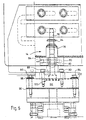
- the ring 34 is shown in Figure 5 held in position on tool 14 prior to being weld-bonded.
- the cylinder head 20 is held by clamps 36, 38 against an inclined face of a wedged-shape mounting 40, made of copper, such that the axis of the valve bore 26 is vertical.
- the mounting 40 is connected via an electrically insulated layer 42 and adapter plate 43 to a member 44, which in turn is mounted for horizontal sliding movement from a fixed slide unit 45 (shown chain-dotted in Figure 4) forming part of the overhead support 18.
- the electric cable 24 is connected co the mounting 40 such that the layer 42 electrically insulates the upper part of the support 18 from the electric power supply.
- Horizontal movement of the member 44 (and nence of the cylinder head 20) along the slide unit 46 is effected by an AC servopositioning motor and decoder 47 ( Figure 2).
- the position of the member 44 is determined by a position detector 48 which sends pulses to the decoder, thereby enabling the latter to count pulses from a "zero home" position and so identify the position of the slide unit.
- each of the tools 14, 16 is independently movable in a vertical direction, typically by a distance of approximately 155mm, by means of thrust rods 54, 56 actuated by two-stage pneumatic cylinders 50, 52 respectively.
- the left-hand cylinder 52 and rod 56 are shown in section, and the retracted rod 56 can be seen mounted for vertical sliding movement in a linear ball bearing 58.
- the tool 16 is connected to the rod 56 by a coupling comprising upper and lower thrust bearings 60, 62 respectively, which allow the tool 15 a limited degree of radial movement in order to accommodate any initial misalignment between the tool and the valve bore (such as bore 26) in the cylinder head 20.
- the tool 14 is likewise coupled by alignable thrust bearings, similar to the bearings 60, 62.
- FIGS. 2 and 3 also show a loading unit, comprising a table 64 which is vertically moveable by means of a pneumatic ram 66, enabling a cylinder head 20 to be raised to the required position for it to be clamped to the mounting 40 when located thereabove, and likewise to be lowered for removal from the machine.
- a loading unit comprising a table 64 which is vertically moveable by means of a pneumatic ram 66, enabling a cylinder head 20 to be raised to the required position for it to be clamped to the mounting 40 when located thereabove, and likewise to be lowered for removal from the machine.
- FIG. 5 there is shown a feed unit for loading seating rings 34 onto a single tool, such as the tool 14.
- a conveyor mechanism 68 feeds rings in a single line to a pick-up position.
- a suction head 70 fixed to an arm 72 locates and grips a ring.
- the arm 72 is pivotally mounted above a shaft 74 which is also vertically moveable by a cam (not shown), typically by a distance of 60mm.
- a cam typically by a distance of 60mm.
- the head 70 is lifted to the position shown at 70 and is then moved by the arm 72 through an angle of about 180°.
- the centre of the ring is aligned with the axis of the tool 14.
- the head is then lowered and suction released, so that the ring is positioned on the tool above a cylindrical nose or pilot portion 76 of the tool.
- the arm 72 For use with the two tools 14, 16, the arm 72 carries a second suction head (not shown), similar to the head 70, and spaced apart by the same distance as the spacing between the tools 14 and 16, enabling the unit to deposit a ring onto each of the tools in a single operation.
- a second suction head (not shown), similar to the head 70, and spaced apart by the same distance as the spacing between the tools 14 and 16, enabling the unit to deposit a ring onto each of the tools in a single operation.
- Figure 6 is an enlarged detail view of the electrode tool 14 showing a removable locator member 73 adapted to support the ring 34. Since different diameter rings may be required for a cylinder block, i.e. for the exhaust and inlet valves, the locator member - 5 can be removed and replaced by a similar member of different diameter.
- the tool 14 incorporates a cooling block 80 having a passage 82 extending around the centre of the tool which is generally of U-shape as viewed from above. Threaded ports 84 at the ends of the passage 82 enable flexible hoses (not shown) to be connected to the passage so as to allow coolant fluid to be fed thereto.
- the tool 14 is connected via an intermediate block 86 (see also Figure 3) to the top of the respective two-stage cylinder 50 or 52 by upper bolts 88, 90 and lower bolts 92, 94.
- an insulating layer 96 is interposed and insulating washers 98, 100 are fitted beneath the heads of the bolts 92 and 94 respectively.
- an insulating layer 102 is fitted between the bottom face of the tool 14 and the intermediate member 86 to act as a double insulation.
- a valve seating ring 34 is deposited by the feed unit onto each electrode tool.
- the motor 47 then moves the slidable member 44, and hence the cylinder head, into the correct position so that the tool 14 is in alignment with the bore 26, and the tool 16 is in alignment with a similar bore in the head 20 disposed behind the bore 26, as viewed in Figure 1.
- Electric power is next connected to the cable 24 and at first to the cable 22 for the tool 14.
- Coolant fluid is fed to the passages 2 of both tools 14 and 16 which are then raised by the cylinders 50, 52 to bring the rings thereon into contact with the respective annular recesses 30 in the cylinder head.
- the nose 76 of each tool (which may additionally be made of electrically nonconductive material) enters the respective bore 26, 28, any minor misalignment being taken care of by the thrust bearings 60, 62.
- an air knife may blow cool air into that region.
- coolant is fed to internal passages (not shown in the mounting 40 to reduce ite temperature and that of the cylinder head clamped thereon.
- the motor 47 is then actuated to move the cylinder head to the next location requiring seating rings to be welded thereon.
- the cylinder head 20 is removed and reclamped to the mounting 40 with the other bank of bores including bore 26, which will now be vertically disposed.
- appropriately sized seating rings are then welded in position in the recesses 72 of respective bores 28 in a similar manner as described above.
Landscapes
- Engineering & Computer Science (AREA)
- Mechanical Engineering (AREA)
- General Engineering & Computer Science (AREA)
- Cylinder Crankcases Of Internal Combustion Engines (AREA)
- Automatic Assembly (AREA)
- Lift Valve (AREA)
- Adhesives Or Adhesive Processes (AREA)
- Resistance Welding (AREA)
- Pressure Welding/Diffusion-Bonding (AREA)
Abstract
Description
Claims (19)
- A method of fitting a valve seating ring (34) in an annular recess (30) in an engine component (20), such as a cylinder head comprising the steps of:a) supporting the engine component above a workstation so that the recess which is to receive the valve seating ring faces in a generally downward direction;b) positioning the ring at the upper end of a tool (14) which forms part of the workstation and is adapted to be moved in an upward direction towards the component supported thereabove;c) moving the tool upwards so that the upper end enters the recess and positions the seating ring accurately therein;d) exerting an upward force so as to press the ring uniformly against at least one region of the recess into which it is to be fixed;e) causing an electric current to flow across the junction between the ring and the component so as to locally heat and cause a plastic deformation of the component material around the ring, to weld-bond the ring to the component;f) terminating the flow of current to allow the site to cool; andg) removing the tool and leaving the seating ring bonded to the component, to form the valve seating.
- A method according to claim 1 in which the component (20) is indexed so as to present different ones of a plurality of recesses (30) therein in alignment with said tool (14) so as to allow each of the recesses to be fitted with seating ring.
- A method according to claim 2 in which the tool (14) or the component support (18) is mounted so as to accommodate any misalignment, so as to enable the axis of the recess (30) in which the ring (34) is to be fitted to be aligned with the axis of movement of the tool.
- Apparatus for fitting a valve seating ring (34) in an annular recess (30) in an engine component (20), comprising component support means (18) positioned adjacent and above a workstation, a tool (14) in the workstation, drive means (50) for moving the tool in an upward and downward direction relative to the component support means, means for aligning the tool axis and the support means so that the up and down movement of the tool is in alignment with a given region of the component support, means (78) for locating onto the upper end of the tool a valve seating ring, control means for controlling the drive means to cause the tool to move upwards and position the ring located thereon in a recess in the component carried by the support means, electrical connections (22) between a supply of electric current and the component and the tool so as to cause an electric current to flow from one to the other when contact is made between the ring and the component, means for exerting a force on the tool or the support means or both to push the tool and the support means towards each other so that the ring on the tool is pressed into contact with said recess in order to resistance weld the seating ring in place, said control means also causing the drive means to withdraw the tool in a downward direction clear of the ring when weld-bonded to the component, permitting relative lateral movement between the component support and the tool to allow the latter to be aligned with another region of the component support means or to allow a component carried by the support means to be moved away and replaced by another component for fitting a ring therein.
- Apparatus according to claim 4 in which the tool (14) and/or the component holding device are fluid cooled.
- Apparatus according to claim 4 or claim 5 and further comprising means for directing a jet of fluid towards the component after the bonding has occurred, to cool the ring and the component in the region of the weld-bond.
- Apparatus according to claim 6 in which the jet of fluid is directed in a downward sense so that any material which has spattered from the welding-bonding zone is blown thereby in a downward sense away from the component.
- Apparatus according to any one of claims 4 to 7 in which means is provided in the workstation for collecting and conveying away therefrom any spattered material.
- Apparatus according to any one of claims 4 to 6 in which the tool (14) is formed as an upper and a lower part, the upper part being adapted to receive a valve seating ring thereon and being mounted on the lower part by means so as to be readily movable relative thereto so as to allow the valve seating ring to fit uniformly and accurately into the recess.
- Apparatus according to any one of claims 4 to 9 in which at least two rings are to be weld-bonded to the component, further comprising tool means adapted to support at the upper end thereof a pair of valve seating rings for movement into engagement with and fitting into each of two spaced apart recesses in the component, each of the two valve seating rings being presented to the tooling means in the workstation from a supply of said valve seating rings, and the tooling means being movable to present and insert the valve seating rings located thereon simultaneously into the two recesses, whereby electric current from said supply is caused to flow through the tooling means to weld-bond the pair of valve seating rings in place.
- Apparatus according to claim 10, in which separate electrical paths are provided through the tooling means to the two separate tools carrying the two rings, and a common return path is provided through the cylinder head.
- Apparatus according to claim 11 in which two separate electric current supplies are provided, each of which is adapted separately to supply welding current to each of the two separate welding sites so that if the electrical resistance associated with one of the welding sites is different from that of the other, the magnitude of the electric current, and time for the current to flow, can be controlled accordingly so as to produce a similar weld at each interface.
- Apparatus according to any one of claims 4 to 12 in which control means is provided for controlling the flow, magnitude and duration of the electric current so that whether a single or multiple welding process is employed, the appropriate current and duration of flow is available for each weld site, so that each of the valve seating rings is appropriately welded in position.
- Apparatus according to any one of claims 10 to 13 in which the tooling means comprises two spaced apart noses on which valve seating rings can be positioned, and the means for introducing relative movement between the cooling means and a supported inverted cylinder head causes appropriate movement of both of the noses into the respective spaced apart valve seat recesses, and means for exerting a compressive force first between the one valve seating ring and its recess in the cylinder head, to produce an appropriate thrust on each ring during the application of welding current.
- Apparatus according to claim 14 in which a first lower force is applied just prior to the welding current application, and a second higher force is applied at the same time as, or just after the initiation of the welding current.
- Apparatus according to any one of claims 4 to 15 comprising composite tooling having a plurality of separate tooling elements adapted to present and insert a plurality of valve seating rings simultaneously into each of a corresponding plurality of recesses on the underside of an inverted cylinder head component supported thereabove, so that all of the said plurality of seating rings can be positioned and held in place ready to be weld-bonded in weld site recesses in the cylinder head during a sequence of weld-bond operations, with appropriate relative movement between each of the separate elements of the tooling means and the cylinder head so as to force each of the seatings into the cylinder head recesses into which they are to be secured, just before and during the application of welding current.
- Apparatus according to any one of claims 4 to 16 comprising conveying means for supplying valve seating rings to the workstation, ready to be received in the correct position on the upper end of the tool for conveyance into a recess in the underside of the component.
- Apparatus according to claim 17 in which the conveying means includes an escapement and/or buffer store so that the presentation of the seating rings to the tool is controlled, and occurs as required.
- Apparatus according to claim 17 or claim 18 in which the conveying means comprises an arm (72) rotatable about a vertical axis and carrying a vacuum suction device (70) at its end remote from the pivoting axis, for placement over and picking up of an upturned ring on a conveyor or other feed mechanism, allowing the ring to be lowered over and onto the tool.
Applications Claiming Priority (5)
| Application Number | Priority Date | Filing Date | Title |
|---|---|---|---|
| GBGB9626639.0A GB9626639D0 (en) | 1996-12-21 | 1996-12-21 | Weld bonding machined parts |
| GB9626639 | 1996-12-21 | ||
| GBGB9716625.0A GB9716625D0 (en) | 1997-08-07 | 1997-08-07 | Weld bonding machined parts |
| GB9716625 | 1997-08-07 | ||
| PCT/GB1997/002719 WO1998028523A1 (en) | 1996-12-21 | 1997-10-03 | Method of fitting a valve seating ring and an apparatus therefor |
Publications (2)
| Publication Number | Publication Date |
|---|---|
| EP1007824A1 EP1007824A1 (en) | 2000-06-14 |
| EP1007824B1 true EP1007824B1 (en) | 2001-07-11 |
Family
ID=26310707
Family Applications (1)
| Application Number | Title | Priority Date | Filing Date |
|---|---|---|---|
| EP97944003A Expired - Lifetime EP1007824B1 (en) | 1996-12-21 | 1997-10-03 | Method of fitting a valve seating ring and an apparatus therefor |
Country Status (9)
| Country | Link |
|---|---|
| US (1) | US6259054B1 (en) |
| EP (1) | EP1007824B1 (en) |
| JP (1) | JP2001507100A (en) |
| KR (1) | KR20000062272A (en) |
| AT (1) | ATE203091T1 (en) |
| DE (1) | DE69705644T2 (en) |
| ES (1) | ES2160368T3 (en) |
| GB (1) | GB2320452B (en) |
| WO (1) | WO1998028523A1 (en) |
Families Citing this family (4)
| Publication number | Priority date | Publication date | Assignee | Title |
|---|---|---|---|---|
| US6401336B1 (en) * | 1999-08-26 | 2002-06-11 | Morrow Tech Industries, Llc | Resistance welding of spray gun valve assembly |
| JP3571605B2 (en) * | 2000-03-16 | 2004-09-29 | 川田鉄工株式会社 | Machining center index device |
| US7022372B1 (en) | 2002-11-12 | 2006-04-04 | Advanced Cardiovascular Systems, Inc. | Compositions for coating implantable medical devices |
| KR100611365B1 (en) | 2004-11-17 | 2006-08-11 | 주식회사 이랜텍 | Battery cell automatic welding device |
Family Cites Families (6)
| Publication number | Priority date | Publication date | Assignee | Title |
|---|---|---|---|---|
| US5742020A (en) * | 1995-01-23 | 1998-04-21 | Yamaha Hatsudoki Kabushiki Kaisha | Valve seat-bonded cylinder head and method for producing same |
| JP3373317B2 (en) * | 1995-02-16 | 2003-02-04 | ヤマハ発動機株式会社 | Valve seat structure of cylinder head |
| JPH08270500A (en) * | 1995-03-31 | 1996-10-15 | Yamaha Motor Co Ltd | Internal combustion engine |
| EP0740054B1 (en) * | 1995-04-26 | 2003-03-12 | Yamaha Hatsudoki Kabushiki Kaisha | Method for producing a cylinder head |
| JP3394363B2 (en) * | 1995-06-28 | 2003-04-07 | ヤマハ発動機株式会社 | Engine cylinder head |
| JPH0979014A (en) * | 1995-09-14 | 1997-03-25 | Yamaha Motor Co Ltd | Manufacturing method of engine cylinder head |
-
1997
- 1997-10-03 ES ES97944003T patent/ES2160368T3/en not_active Expired - Lifetime
- 1997-10-03 DE DE69705644T patent/DE69705644T2/en not_active Expired - Fee Related
- 1997-10-03 KR KR1019997005645A patent/KR20000062272A/en not_active Withdrawn
- 1997-10-03 US US09/308,209 patent/US6259054B1/en not_active Expired - Fee Related
- 1997-10-03 AT AT97944003T patent/ATE203091T1/en active
- 1997-10-03 EP EP97944003A patent/EP1007824B1/en not_active Expired - Lifetime
- 1997-10-03 JP JP52849798A patent/JP2001507100A/en active Pending
- 1997-10-03 WO PCT/GB1997/002719 patent/WO1998028523A1/en not_active Ceased
- 1997-10-06 GB GB9721004A patent/GB2320452B/en not_active Expired - Fee Related
Also Published As
| Publication number | Publication date |
|---|---|
| DE69705644D1 (en) | 2001-08-16 |
| DE69705644T2 (en) | 2002-03-14 |
| KR20000062272A (en) | 2000-10-25 |
| JP2001507100A (en) | 2001-05-29 |
| GB2320452B (en) | 1999-02-03 |
| EP1007824A1 (en) | 2000-06-14 |
| US6259054B1 (en) | 2001-07-10 |
| ATE203091T1 (en) | 2001-07-15 |
| GB2320452A (en) | 1998-06-24 |
| GB9721004D0 (en) | 1997-12-03 |
| WO1998028523A1 (en) | 1998-07-02 |
| ES2160368T3 (en) | 2001-11-01 |
Similar Documents
| Publication | Publication Date | Title |
|---|---|---|
| US6512195B2 (en) | Modular welding machine | |
| US4951386A (en) | Apparatus for disassembling bearing caps and assembling metals | |
| US5403988A (en) | Stud welding apparatus | |
| CN103506797B (en) | Rotating shaft welding fixture, workbench and rotating shaft robot welding system | |
| CN106216868B (en) | A kind of welding method and special fixture of heavy axle stiffening ring | |
| US4603456A (en) | Machining equipment for production lines | |
| JP3055678B2 (en) | Resistance welding apparatus and its electrode unit | |
| CN211540234U (en) | Automatic annular production line of restoreing of aluminium electroloysis anode rod | |
| US6259054B1 (en) | Method of fitting a valve seating ring and an apparatus therefor | |
| CN106216828A (en) | Electricity servo c-type robot soldering pliers | |
| CN112159992A (en) | Automatic repair production line and repair method for flow-splitting aluminum electrolysis anode steel claw | |
| US5031819A (en) | Automatic braze welding apparatus | |
| CN113560359B (en) | Titanium alloy seamless tube processing technology and processing device thereof | |
| CN107498166B (en) | Chain saw guide plate dislocation spot-welding equipment | |
| US9616517B2 (en) | Removable welding tip assembly | |
| JPH05263125A (en) | Full automatic high-frequency induction quenching device | |
| CN219632803U (en) | Welding device | |
| CN218964662U (en) | Aluminum-steel direct welding system for aluminum electrolysis | |
| US3743815A (en) | System for producing valves as for internal-combustion engines | |
| KR100246523B1 (en) | A robot hand for trimming and a device for exchanging automatically cutter | |
| CN116871633A (en) | Bipolar plate welding device | |
| CN110695497B (en) | Automatic TIG welding method for helium tube of large superconducting magnet coil | |
| JP3025523B2 (en) | Automatic coil changer for induction hardening equipment | |
| JPH0775778B2 (en) | Welding equipment for chip parts for engine valves | |
| US2935596A (en) | Fusing machine |
Legal Events
| Date | Code | Title | Description |
|---|---|---|---|
| PUAI | Public reference made under article 153(3) epc to a published international application that has entered the european phase |
Free format text: ORIGINAL CODE: 0009012 |
|
| 17P | Request for examination filed |
Effective date: 19990423 |
|
| AK | Designated contracting states |
Kind code of ref document: A1 Designated state(s): AT BE DE ES FR IT SE |
|
| GRAG | Despatch of communication of intention to grant |
Free format text: ORIGINAL CODE: EPIDOS AGRA |
|
| 17Q | First examination report despatched |
Effective date: 20000822 |
|
| GRAG | Despatch of communication of intention to grant |
Free format text: ORIGINAL CODE: EPIDOS AGRA |
|
| GRAH | Despatch of communication of intention to grant a patent |
Free format text: ORIGINAL CODE: EPIDOS IGRA |
|
| GRAH | Despatch of communication of intention to grant a patent |
Free format text: ORIGINAL CODE: EPIDOS IGRA |
|
| RBV | Designated contracting states (corrected) |
Designated state(s): AT BE DE ES FR IT SE |
|
| GRAA | (expected) grant |
Free format text: ORIGINAL CODE: 0009210 |
|
| ITF | It: translation for a ep patent filed | ||
| AK | Designated contracting states |
Kind code of ref document: B1 Designated state(s): AT BE DE ES FR IT SE |
|
| REF | Corresponds to: |
Ref document number: 203091 Country of ref document: AT Date of ref document: 20010715 Kind code of ref document: T |
|
| REF | Corresponds to: |
Ref document number: 69705644 Country of ref document: DE Date of ref document: 20010816 |
|
| PG25 | Lapsed in a contracting state [announced via postgrant information from national office to epo] |
Ref country code: AT Free format text: LAPSE BECAUSE OF NON-PAYMENT OF DUE FEES Effective date: 20011003 |
|
| PG25 | Lapsed in a contracting state [announced via postgrant information from national office to epo] |
Ref country code: ES Free format text: LAPSE BECAUSE OF NON-PAYMENT OF DUE FEES Effective date: 20011004 |
|
| PG25 | Lapsed in a contracting state [announced via postgrant information from national office to epo] |
Ref country code: BE Free format text: LAPSE BECAUSE OF NON-PAYMENT OF DUE FEES Effective date: 20011031 |
|
| REG | Reference to a national code |
Ref country code: ES Ref legal event code: FG2A Ref document number: 2160368 Country of ref document: ES Kind code of ref document: T3 |
|
| ET | Fr: translation filed | ||
| PGFP | Annual fee paid to national office [announced via postgrant information from national office to epo] |
Ref country code: SE Payment date: 20020215 Year of fee payment: 5 Ref country code: FR Payment date: 20020215 Year of fee payment: 5 |
|
| BERE | Be: lapsed |
Owner name: UNOVA U.K. LTD Effective date: 20011031 |
|
| PLBE | No opposition filed within time limit |
Free format text: ORIGINAL CODE: 0009261 |
|
| STAA | Information on the status of an ep patent application or granted ep patent |
Free format text: STATUS: NO OPPOSITION FILED WITHIN TIME LIMIT |
|
| PG25 | Lapsed in a contracting state [announced via postgrant information from national office to epo] |
Ref country code: DE Free format text: LAPSE BECAUSE OF NON-PAYMENT OF DUE FEES Effective date: 20020702 |
|
| 26N | No opposition filed | ||
| PG25 | Lapsed in a contracting state [announced via postgrant information from national office to epo] |
Ref country code: SE Free format text: LAPSE BECAUSE OF NON-PAYMENT OF DUE FEES Effective date: 20021004 |
|
| EUG | Se: european patent has lapsed | ||
| PG25 | Lapsed in a contracting state [announced via postgrant information from national office to epo] |
Ref country code: FR Free format text: LAPSE BECAUSE OF NON-PAYMENT OF DUE FEES Effective date: 20030630 |
|
| REG | Reference to a national code |
Ref country code: FR Ref legal event code: ST |
|
| REG | Reference to a national code |
Ref country code: ES Ref legal event code: FD2A Effective date: 20021113 |
|
| PG25 | Lapsed in a contracting state [announced via postgrant information from national office to epo] |
Ref country code: IT Free format text: LAPSE BECAUSE OF NON-PAYMENT OF DUE FEES;WARNING: LAPSES OF ITALIAN PATENTS WITH EFFECTIVE DATE BEFORE 2007 MAY HAVE OCCURRED AT ANY TIME BEFORE 2007. THE CORRECT EFFECTIVE DATE MAY BE DIFFERENT FROM THE ONE RECORDED. Effective date: 20051003 |