EP1007339B1 - Diaphragm press - Google Patents
Diaphragm press Download PDFInfo
- Publication number
- EP1007339B1 EP1007339B1 EP98902874A EP98902874A EP1007339B1 EP 1007339 B1 EP1007339 B1 EP 1007339B1 EP 98902874 A EP98902874 A EP 98902874A EP 98902874 A EP98902874 A EP 98902874A EP 1007339 B1 EP1007339 B1 EP 1007339B1
- Authority
- EP
- European Patent Office
- Prior art keywords
- platen assemblies
- press
- membrane
- flexible membrane
- diaphragm press
- Prior art date
- Legal status (The legal status is an assumption and is not a legal conclusion. Google has not performed a legal analysis and makes no representation as to the accuracy of the status listed.)
- Expired - Lifetime
Links
Images

Classifications
-
- B—PERFORMING OPERATIONS; TRANSPORTING
- B30—PRESSES
- B30B—PRESSES IN GENERAL
- B30B1/00—Presses, using a press ram, characterised by the features of the drive therefor, pressure being transmitted directly, or through simple thrust or tension members only, to the press ram or platen
- B30B1/003—Presses, using a press ram, characterised by the features of the drive therefor, pressure being transmitted directly, or through simple thrust or tension members only, to the press ram or platen by an elastic bag or diaphragm expanded by fluid pressure
-
- B—PERFORMING OPERATIONS; TRANSPORTING
- B30—PRESSES
- B30B—PRESSES IN GENERAL
- B30B5/00—Presses characterised by the use of pressing means other than those mentioned in the preceding groups
- B30B5/02—Presses characterised by the use of pressing means other than those mentioned in the preceding groups wherein the pressing means is in the form of a flexible element, e.g. diaphragm, urged by fluid pressure
Definitions
- This invention relates to diaphragm presses for thermolaminating and in particular to improvements in thermolaminating passes including membrane form presses.
- Instances where the risk of creasing or wrinkling is high include medium to large workpieces (eg 1200 mm - 2400 mm or longer), irregular or perforated components (eg frames), thermofoils which are unstable when exposed to heat due to type, gauge, or the release of captive process stresses, hygroscopic materials which become unstable when in contact with a wet, water-based glue line (which causes undulations) (eg veneers or paper), and free standing components which must be straight after process curing temperatures and heat resistance have been achieved (eg 2400 mm high pantry doors or panels).
- medium to large workpieces eg 1200 mm - 2400 mm or longer
- irregular or perforated components eg frames
- thermofoils which are unstable when exposed to heat due to type, gauge, or the release of captive process stresses
- hygroscopic materials which become unstable when in contact with a wet, water-based glue line (which causes undulations) (eg veneers or paper)
- free standing components
- EP 0749824 A2 discloses a hot platen welder press for fusing thermoplastic sheets, including upper and lower platen assemblies, with each platen assembly including a diaphragm set of two compliant membranes.
- a moulding machine comprising a diaphragm is known from document US-A-3 284 858.
- a membrane that can be either flexible or rigid we have discovered that it is possible to provide a membrane that can be flexible or rigid as required. We have achieved this by installing, on the side of the membrane remote from the workpiece, a platen assembly which can be moved independently of and relative to the combination frame (also known as an "L" frame) and/or other frames, trays, tables, or conveyors of the press and which can bring the membrane into contact with the workpiece.
- a platen assembly may include a vented heating plate allowing the application of heat and pressure to the workpiece via the membrane as required.
- Parts of the surfaces of the platen assembly of the invention and the combination frame make positive contact when the platen assembly is retracted and are held or locked together to establish a seal. This results in re-establishment of the chamber of the press, and the press then functions as a normal diaphragm press in which heat, pressure and vacuum can be applied in accordance with current technology.
- a multi-function diaphragm press including upper and lower platen assemblies separated by a flexible membrane, one of said platen assemblies being movable between a first position whereby said one of said platen assemblies does not contact said flexible membrane and a second position whereby said flexible membrane is in contact with said one of said platen assemblies to provide a rigid membrane, characterised in that in said first position said one of said platen assemblies cooperates with a frame of said multi-function diaphragm press and said membrane to provide a pressure chamber, whereby said flexible membrane can contact a workpiece inserted between said flexible membrane and the other of said platen assemblies allowing said flexible membrane to follow the contours of said workpiece.
- said one of said platen assemblies is moved by hydraulic means.
- said one of said platen assemblies can be installed in either the top or the bottom half of the press.
- two independently movable platen assemblies can be installed in the press, one in either half. It is also possible that more than one independently movable platen assembly may be installed in either half of the press.
- each platen assembly includes a plate, hereinafter called a bolster, a heating means and a vented heat exchanging means.
- a plate hereinafter called a bolster
- a heating means Preferably the plate is made of steel.
- a vented heat exchanging means Preferably the plate is made of steel.
- an independently movable platen assembly is installed in the top half of a diaphragm press it provides a rigid surface adjustable by raising or lowering the platen assembly in the top half of the normally flexible press without the need to remove or add parts to the press. Retraction, sealing and/or locking of the independently movable platen assembly against the combination frame lip permits normal diaphragm press operation.
- a significant advantage is that a workpiece can be flat surface-pressed with the rigid surface provided by the lowered independently movable platen assembly and, if required, flexibly 3-D pressed immediately afterward. This is particularly useful for pressing large or unusual objects or where the surface coating materials vary in type, gauge, thermal stability or memory effects or where instability affects flatness such as where a hygroscopic material like veneer contacts a wet glue line.
- a significant reduction in losses due to creasing of surface coatings during the pressing process can be achieved by rigid membrane flat pressing of surface coating to flat surfaces of the object or workpiece prior to a rapid changeover to flexible 3-D pressing to complete the forming and bonding of the surface coating to the surfaces of the object or workpiece.
- the numeral 10 designates generally a diaphragm press.
- Press 10 utilises a pressure bag or bladder 12 under a lower bolster 14, preferably formed of steel.
- the source of pressure may air or hydraulic.
- the upper face of an independently movable bolster 16 of an independently movable platen assembly is mounted on shafts 18 of pistons (not shown) of hydraulic cylinders 20, the pistons being capable of being lowered or retracted as required.
- An insulating layer 22 is fixed to the lower face of bolster 16 to insulate bolster 16 from a heating means 24.
- a vented heat exchanging means 26 is fixed to the underside of heating means 24.
- the hydraulic cylinders 20 are mounted on a frame 28 independent of a combination frame 30 of the press 10.
- the independently movable platen assembly (formed by bolster 16, insulating layer 22, heating means 24 and vented heat exchanging means 26) is lowered and contacts a membrane 32 to provide a so-called "rigid membrane".
- This enables flat pressing of a workpiece which is normally positioned on a base board (not shown) in chamber 34 above lower vented heat exchanging means 36.
- the upper face of bottom steel bolster 14 is covered by lower insulating layer 40 insulating bolster 14 from lower heating means 38.
- the numerals 42 and 44 respectively designate the loading tray and portion of the fixed or moving frame of press 10, while numeral 46 designates the press base bolster.
- Fig. 2 shows retraction of the platen assembly to provide a standard flexible membrane press.
- the sealing 48 between the upper face of bolster 16 and the combination frame 30 results in the formation of a pressurizable chamber 50 as in conventional diaphragm presses.
- the surface(s) of the workpiece to be processed are sealed by the spray application of a quality glue line taking into account variations in absorption rates, and allowed to flush off as per manufacturer's instructions.
- Standard jigging, base board and foil preparation then can be completed.
- the workpiece can then be recoated with an even coat of glue and allowed to dry or it can be placed on the base board with a wet tacky coat of adhesive, then covered by the foil to be attached.
- a dry adhesive file can be placed between the foil and the workpiece, or the workpiece can be covered with adhesive-backed foil.
- This resultant assembly can be inserted via the tray, table or belt into the pressure chamber which is subsequently closed.
- This cycle includes the steps of causing the independently movable platen to make contact via the membrane with the top surface of the component either once or several times for predetermined periods of time.
- the foil becomes firmly attached to the workpiece.
- no air pressure is required in the chamber.
- the independently movable platen assembly is then retracted and locked and sealed to the combination frame and standard press cycles are resumed as required. With the foil firmly attached to all top surfaces of the workpiece the risk of creasing during pre-heat and final forming is significantly reduced.
Abstract
Description
- This invention relates to diaphragm presses for thermolaminating and in particular to improvements in thermolaminating passes including membrane form presses.
- Existing press technologies essentially are divided into two types - (1) day light presses, where pressing is done between two rigid plates; and (2) diaphragm presses, also known as membrane or membraneless presses, where an object or workpiece is pressed between a flexible surface and a rigid plate or between two flexible surfaces. In membrane presses the membrane seals a pressurizable chamber. When the chamber is pressurised the membrane conforms to the shape of the workpiece. Additionally vacuum may be applied to the other side of the workpiece via a vented lower platen.
- As the size of the object or workpiece increases it becomes more difficult to maintain quality. This is reflected by the increasing rate of rejects caused by unrepairable creases or wrinkles in the surface finish applied by the diaphragm press. The increase in rejection rate is a significant economic cost. Instances where the risk of creasing or wrinkling is high include medium to large workpieces (eg 1200 mm - 2400 mm or longer), irregular or perforated components (eg frames), thermofoils which are unstable when exposed to heat due to type, gauge, or the release of captive process stresses, hygroscopic materials which become unstable when in contact with a wet, water-based glue line (which causes undulations) (eg veneers or paper), and free standing components which must be straight after process curing temperatures and heat resistance have been achieved (eg 2400 mm high pantry doors or panels).
- EP 0749824 A2 discloses a hot platen welder press for fusing thermoplastic sheets, including upper and lower platen assemblies, with each platen assembly including a diaphragm set of two compliant membranes.
- A moulding machine comprising a diaphragm is known from document US-A-3 284 858.
- Present day diaphragm presses do not offer a membrane that can be either flexible or rigid. We have discovered that it is possible to provide a membrane that can be flexible or rigid as required. We have achieved this by installing, on the side of the membrane remote from the workpiece, a platen assembly which can be moved independently of and relative to the combination frame (also known as an "L" frame) and/or other frames, trays, tables, or conveyors of the press and which can bring the membrane into contact with the workpiece. Such a platen assembly may include a vented heating plate allowing the application of heat and pressure to the workpiece via the membrane as required. Parts of the surfaces of the platen assembly of the invention and the combination frame make positive contact when the platen assembly is retracted and are held or locked together to establish a seal. This results in re-establishment of the chamber of the press, and the press then functions as a normal diaphragm press in which heat, pressure and vacuum can be applied in accordance with current technology.
- According to the present invention there is provided a multi-function diaphragm press including upper and lower platen assemblies separated by a flexible membrane, one of said platen assemblies being movable between a first position whereby said one of said platen assemblies does not contact said flexible membrane and a second position whereby said flexible membrane is in contact with said one of said platen assemblies to provide a rigid membrane, characterised in that in said first position said one of said platen assemblies cooperates with a frame of said multi-function diaphragm press and said membrane to provide a pressure chamber, whereby said flexible membrane can contact a workpiece inserted between said flexible membrane and the other of said platen assemblies allowing said flexible membrane to follow the contours of said workpiece. Preferably said one of said platen assemblies is moved by hydraulic means.
- Preferably said one of said platen assemblies can be installed in either the top or the bottom half of the press. Alternatively, two independently movable platen assemblies can be installed in the press, one in either half. It is also possible that more than one independently movable platen assembly may be installed in either half of the press.
- Preferably each platen assembly includes a plate, hereinafter called a bolster, a heating means and a vented heat exchanging means. Preferably the plate is made of steel.
- Where an independently movable platen assembly is installed in the top half of a diaphragm press it provides a rigid surface adjustable by raising or lowering the platen assembly in the top half of the normally flexible press without the need to remove or add parts to the press. Retraction, sealing and/or locking of the independently movable platen assembly against the combination frame lip permits normal diaphragm press operation.
- A significant advantage is that a workpiece can be flat surface-pressed with the rigid surface provided by the lowered independently movable platen assembly and, if required, flexibly 3-D pressed immediately afterward. This is particularly useful for pressing large or unusual objects or where the surface coating materials vary in type, gauge, thermal stability or memory effects or where instability affects flatness such as where a hygroscopic material like veneer contacts a wet glue line. A significant reduction in losses due to creasing of surface coatings during the pressing process can be achieved by rigid membrane flat pressing of surface coating to flat surfaces of the object or workpiece prior to a rapid changeover to flexible 3-D pressing to complete the forming and bonding of the surface coating to the surfaces of the object or workpiece.
- In order that the invention may be more clearly understood reference is now made to schematic illustrations of one embodiment of the invention in which:-
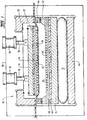
- Fig. 1 depicts a section through a press with an independently movable platen assembly in a lowered position; and
- Fig. 2 is the same view showing the press being used as a flexible membrane diaphragm press.
- In the drawings the
numeral 10 designates generally a diaphragm press.Press 10 utilises a pressure bag orbladder 12 under alower bolster 14, preferably formed of steel. The source of pressure may air or hydraulic. The upper face of an independentlymovable bolster 16 of an independently movable platen assembly is mounted onshafts 18 of pistons (not shown) ofhydraulic cylinders 20, the pistons being capable of being lowered or retracted as required. Aninsulating layer 22 is fixed to the lower face ofbolster 16 to insulatebolster 16 from a heating means 24. A vented heat exchanging means 26 is fixed to the underside of heating means 24. Thehydraulic cylinders 20 are mounted on a frame 28 independent of acombination frame 30 of thepress 10. When the pistons are lowered, the independently movable platen assembly (formed bybolster 16,insulating layer 22, heating means 24 and vented heat exchanging means 26) is lowered and contacts amembrane 32 to provide a so-called "rigid membrane". This enables flat pressing of a workpiece which is normally positioned on a base board (not shown) inchamber 34 above lower vented heat exchanging means 36. Similarly, the upper face ofbottom steel bolster 14 is covered by lower insulatinglayer 40 insulatingbolster 14 from lower heating means 38. Thenumerals press 10, whilenumeral 46 designates the press base bolster. - Fig. 2 shows retraction of the platen assembly to provide a standard flexible membrane press. The sealing 48 between the upper face of
bolster 16 and thecombination frame 30 results in the formation of apressurizable chamber 50 as in conventional diaphragm presses. - When using the press with a sprayable glue line, also referred to as adhesive, the surface(s) of the workpiece to be processed are sealed by the spray application of a quality glue line taking into account variations in absorption rates, and allowed to flush off as per manufacturer's instructions.
- Standard jigging, base board and foil preparation then can be completed. The workpiece can then be recoated with an even coat of glue and allowed to dry or it can be placed on the base board with a wet tacky coat of adhesive, then covered by the foil to be attached. Alternatively, a dry adhesive file can be placed between the foil and the workpiece, or the workpiece can be covered with adhesive-backed foil.
- This resultant assembly can be inserted via the tray, table or belt into the pressure chamber which is subsequently closed.
- An appropriate cycle for the operation of the press is selected. This cycle includes the steps of causing the independently movable platen to make contact via the membrane with the top surface of the component either once or several times for predetermined periods of time. As a result, the foil becomes firmly attached to the workpiece. During this stage no air pressure is required in the chamber. The independently movable platen assembly is then retracted and locked and sealed to the combination frame and standard press cycles are resumed as required. With the foil firmly attached to all top surfaces of the workpiece the risk of creasing during pre-heat and final forming is significantly reduced.
- It is to be understood that variations and modifications can be made to the embodiment described, within the scope of the appended claims.
Claims (6)
- A multi-function diaphragm press including upper and lower platen assemblies (16, 22, 24, 26; 14, 40, 38, 36), separated by a flexible membrane (32), one of said platen assemblies (16, 22, 24, 26) being movable between a first position whereby said one of said platen assemblies does not contact said flexible membrane and a second position whereby said flexible membrane is in contact with said one of said platen assemblies to provide a rigid membrane, characterised in that in said first position said one of said platen assemblies (16, 22, 24, 26) cooperates with a frame (30) of said multi-function diaphragm press and said membrane (32) to provide a pressure chamber (50), whereby said flexible membrane (32) can contact a workpiece inserted between said flexible membrane and the other of said platen assemblies (14, 40, 38, 36) allowing said flexible membrane to follow the contours of said workpiece.
- The multi-function diaphragm press of claim 1, wherein said one of said platen assemblies (16, 22, 24, 26) includes sealing means (48) which cooperates with said frame (30) to ensure fluid tightness of said pressure chamber (50).
- The multi-function diaphragm press of claim 1 or 2, wherein said one of said platen assemblies (16, 22, 24, 26) is moved by hydraulic means (20).
- The multi-function diaphragm press of any one of the preceding claims, wherein each of said platen assemblies (16, 22, 24, 26; 14, 40, 38, 36) includes a plate or bolster (16; 14), a heating means (24; 38) and a vented heat exchanging means (26; 36).
- The multi-function diaphragm press of any one of the preceding claims, wherein the other of said platen assemblies (14, 40, 38, 36) is located on a pressure bag or bladder (12).
- The multi-function diaphragm press of any one of the preceding claims, wherein the other of said platen assemblies (14, 40, 38, 36) is movable.
Applications Claiming Priority (3)
| Application Number | Priority Date | Filing Date | Title |
|---|---|---|---|
| AUPO5313A AUPO531397A0 (en) | 1997-02-25 | 1997-02-25 | Improvements to diaphragm press |
| AUPO531397 | 1997-02-25 | ||
| PCT/AU1998/000111 WO1998038033A1 (en) | 1997-02-25 | 1998-02-20 | Improvements to diaphragm presses |
Publications (3)
| Publication Number | Publication Date |
|---|---|
| EP1007339A4 EP1007339A4 (en) | 2000-06-14 |
| EP1007339A1 EP1007339A1 (en) | 2000-06-14 |
| EP1007339B1 true EP1007339B1 (en) | 2006-04-26 |
Family
ID=3799616
Family Applications (1)
| Application Number | Title | Priority Date | Filing Date |
|---|---|---|---|
| EP98902874A Expired - Lifetime EP1007339B1 (en) | 1997-02-25 | 1998-02-20 | Diaphragm press |
Country Status (8)
| Country | Link |
|---|---|
| US (1) | US6250217B1 (en) |
| EP (1) | EP1007339B1 (en) |
| JP (1) | JP3996206B2 (en) |
| AT (1) | ATE324250T1 (en) |
| AU (1) | AUPO531397A0 (en) |
| DE (1) | DE69834333T2 (en) |
| ES (1) | ES2263198T3 (en) |
| WO (1) | WO1998038033A1 (en) |
Cited By (1)
| Publication number | Priority date | Publication date | Assignee | Title |
|---|---|---|---|---|
| CN108724781A (en) * | 2018-05-29 | 2018-11-02 | 薛春红 | It is a kind of to be pressed together device for material processing |
Families Citing this family (16)
| Publication number | Priority date | Publication date | Assignee | Title |
|---|---|---|---|---|
| DE10352754B3 (en) * | 2003-11-12 | 2005-06-30 | Bachmann Kunststoff Technologien Gmbh | Hot-pressing device with a press plate and at least one elastic coating |
| DE102005031416B4 (en) * | 2005-07-04 | 2007-06-14 | Meier Vakuumtechnik Gmbh | membrane press |
| US8746132B2 (en) * | 2005-08-12 | 2014-06-10 | Lawrence Equipment Inc. | Heated discharge platen for dough processing system |
| EP2002915B1 (en) * | 2006-03-15 | 2011-10-12 | NGK Insulators, Ltd. | Method of fabricating dissimilar material jointed body |
| US8109314B1 (en) | 2007-06-07 | 2012-02-07 | Santiago Rodriguez | Air clamp |
| DE102007041261B3 (en) * | 2007-08-30 | 2009-03-19 | Meier Vakuumtechnik Gmbh | Laminator, pressure membrane and method for laminating component stacks |
| WO2009135123A2 (en) * | 2008-05-01 | 2009-11-05 | Lawrence Equipment, Inc. | Vacuum pressing platen assembly and method for adjustment |
| US9199439B2 (en) | 2008-07-22 | 2015-12-01 | 3Form, Llc | Efficient lamination press with thin flexible platens |
| EP2189283A1 (en) * | 2008-11-21 | 2010-05-26 | komax Holding AG | Apparatus for laminating a solar cell modul |
| DE102009020991A1 (en) * | 2009-05-12 | 2010-11-18 | Robert Bürkle GmbH | Press for laminating substantially plate-shaped workpieces |
| DE202009018528U1 (en) * | 2009-10-09 | 2012-02-27 | Fotoverbundglas Marl Gmbh | Device for producing laminated safety glass |
| US8689685B2 (en) | 2010-11-04 | 2014-04-08 | Lawrence Equipment Inc. | Dough forming pressing plate with spacers |
| RU2466862C1 (en) * | 2011-05-19 | 2012-11-20 | Общество с ограниченной ответственностью "Малое инновационное предприятие "Декор-БГИТА" | Method of manufacturing facing shield with embossed multicoloured surface |
| US8662313B2 (en) | 2011-07-20 | 2014-03-04 | Lawrence Equipment Inc. | Systems and methods for processing comestibles |
| WO2014058474A1 (en) * | 2012-10-11 | 2014-04-17 | Hunter Douglas Industries Switzerland Gmbh | Efficient lamination press with thin flexible platens |
| DE102018101470A1 (en) | 2018-01-23 | 2019-07-25 | Robert Bürkle GmbH | Laminating apparatus and method for laminating at least one layer stack |
Citations (1)
| Publication number | Priority date | Publication date | Assignee | Title |
|---|---|---|---|---|
| US3284858A (en) * | 1964-02-18 | 1966-11-15 | Molding machine and head with pressure compensating provision |
Family Cites Families (14)
| Publication number | Priority date | Publication date | Assignee | Title |
|---|---|---|---|---|
| DE1007047B (en) | 1956-02-18 | 1957-04-25 | Becker & Van Huellen | Hydraulic hot plate press |
| DE1279613B (en) | 1964-08-20 | 1968-10-10 | August Laepple G M B H & Co We | Press with a cushion plate that is resiliently influenced by a pressure medium |
| US3850559A (en) * | 1973-04-18 | 1974-11-26 | Unisil Molds Inc | Apparatus for vulcanizing rubber molds |
| DE3017258A1 (en) | 1979-02-03 | 1981-11-12 | Helmut Friz Gmbh & Co, 7102 Weinsberg | Preforming appliance for membrane - has support and pressure units inside membrane bounded pressure chamber |
| DE3008485A1 (en) * | 1980-03-05 | 1981-09-10 | Friz, Helmut A., Dipl.-Ing., 7000 Stuttgart | Membrane-fitted moulding press - has workpiece feed mechanism with device allowing exact positioning of workpiece |
| DE3011171A1 (en) | 1980-03-22 | 1981-10-01 | Friz, Helmut A., Dipl.-Ing., 7000 Stuttgart | Veneer pressed and bonded onto three=dimensionally fluted surface - by progressive moulding with tools then distributed pressure on pressing membrane |
| US4450034A (en) * | 1982-06-10 | 1984-05-22 | Atlantic Richfield Company | Laminator for large workpieces |
| US4529472A (en) * | 1982-11-10 | 1985-07-16 | Wei K. Hsu | Impulse sealing apparatus |
| DE3532710A1 (en) | 1985-09-13 | 1987-03-19 | Wemhoener Heinrich Gmbh Co | Diaphragm forming press |
| DE3702679A1 (en) | 1987-01-30 | 1988-08-11 | Robert Hildebrand Maschinen An | Press |
| DE3935562A1 (en) * | 1989-10-25 | 1991-05-02 | Friz Maschinenbau Gmbh | Bag press for e.g. veneering shapes - has fixed lower platen with vacuum bores and moving frame with pressurised membrane contg. fabrics with embedded polyester heater element |
| DE4108936A1 (en) * | 1991-03-19 | 1992-09-24 | Kannegiesser H Gmbh Co | DEVICE FOR GLUING TEXTILE SURFACES |
| DE4310302C2 (en) | 1993-03-30 | 2002-12-05 | Friz Maschb Gmbh | Process and membrane molding press for coating three-dimensional workpieces |
| US5635014A (en) | 1995-06-19 | 1997-06-03 | Gr Systems | Press apparatus and methods for fusing overlapped thermoplastic sheet materials |
-
1997
- 1997-02-25 AU AUPO5313A patent/AUPO531397A0/en not_active Abandoned
-
1998
- 1998-02-20 DE DE69834333T patent/DE69834333T2/en not_active Expired - Lifetime
- 1998-02-20 AT AT98902874T patent/ATE324250T1/en active
- 1998-02-20 WO PCT/AU1998/000111 patent/WO1998038033A1/en active IP Right Grant
- 1998-02-20 JP JP53706798A patent/JP3996206B2/en not_active Expired - Fee Related
- 1998-02-20 ES ES98902874T patent/ES2263198T3/en not_active Expired - Lifetime
- 1998-02-20 US US09/297,195 patent/US6250217B1/en not_active Expired - Fee Related
- 1998-02-20 EP EP98902874A patent/EP1007339B1/en not_active Expired - Lifetime
Patent Citations (1)
| Publication number | Priority date | Publication date | Assignee | Title |
|---|---|---|---|---|
| US3284858A (en) * | 1964-02-18 | 1966-11-15 | Molding machine and head with pressure compensating provision |
Cited By (1)
| Publication number | Priority date | Publication date | Assignee | Title |
|---|---|---|---|---|
| CN108724781A (en) * | 2018-05-29 | 2018-11-02 | 薛春红 | It is a kind of to be pressed together device for material processing |
Also Published As
| Publication number | Publication date |
|---|---|
| US6250217B1 (en) | 2001-06-26 |
| ATE324250T1 (en) | 2006-05-15 |
| ES2263198T3 (en) | 2006-12-01 |
| EP1007339A4 (en) | 2000-06-14 |
| DE69834333T2 (en) | 2007-04-26 |
| WO1998038033A1 (en) | 1998-09-03 |
| EP1007339A1 (en) | 2000-06-14 |
| JP2001513029A (en) | 2001-08-28 |
| DE69834333D1 (en) | 2006-06-01 |
| JP3996206B2 (en) | 2007-10-24 |
| AUPO531397A0 (en) | 1997-03-20 |
Similar Documents
| Publication | Publication Date | Title |
|---|---|---|
| EP1007339B1 (en) | Diaphragm press | |
| JPH05269777A (en) | Hot press | |
| CA2176689A1 (en) | Press Apparatus and Methods for Fusing Overlapped Thermoplastic Sheet Materials | |
| CA2075100A1 (en) | Process for the production of a composite sheet comprising a cellular core and at least one outer layer | |
| JPH07195391A (en) | Hot press | |
| JPH0310501B2 (en) | ||
| JPH03262607A (en) | Molding tool of composite part | |
| US5809858A (en) | Device for achieving optimum leveling of cutting die and platen components in die cutting machines | |
| CA2079043A1 (en) | Method and apparatus for the manufacture of a resealable package | |
| AU718260C (en) | Improvements to diaphragm presses | |
| AU718260B2 (en) | Improvements to diaphragm presses | |
| JPH072485B2 (en) | Container sealing device | |
| US20080181979A1 (en) | Hot press for coating work pieces, in particular furniture parts, as well as work table therefor | |
| JPH0154173B2 (en) | ||
| CN110053269A (en) | Aluminum honeycomb arc panel bonding forming device and method | |
| JP3204569B2 (en) | hot press | |
| JPS5921306B2 (en) | Pasting method for laminated resin molded products | |
| US3806104A (en) | Presses | |
| JPH043747Y2 (en) | ||
| JPS62211129A (en) | Vacuum type hot press | |
| JP3343791B2 (en) | Product movement prevention structure by thermal expansion and contraction | |
| KR970003938B1 (en) | Method for applying transfer picture on funiture | |
| JP2003165160A (en) | Laminator | |
| EP0864414A2 (en) | Hot-plate press for panel pressing | |
| PL315975A1 (en) | Method of and apparatus for making decoartive foamed plastic boards |
Legal Events
| Date | Code | Title | Description |
|---|---|---|---|
| PUAI | Public reference made under article 153(3) epc to a published international application that has entered the european phase |
Free format text: ORIGINAL CODE: 0009012 |
|
| 17P | Request for examination filed |
Effective date: 19990412 |
|
| A4 | Supplementary search report drawn up and despatched |
Effective date: 20000322 |
|
| AK | Designated contracting states |
Kind code of ref document: A4 Designated state(s): AT BE CH DE DK ES FI FR GB GR IE IT LI LU MC NL PT SE Kind code of ref document: A1 Designated state(s): AT BE CH DE DK ES FI FR GB GR IE IT LI LU MC NL PT SE |
|
| 17Q | First examination report despatched |
Effective date: 20040719 |
|
| GRAP | Despatch of communication of intention to grant a patent |
Free format text: ORIGINAL CODE: EPIDOSNIGR1 |
|
| RTI1 | Title (correction) |
Free format text: DIAPHRAGM PRESS |
|
| GRAS | Grant fee paid |
Free format text: ORIGINAL CODE: EPIDOSNIGR3 |
|
| GRAA | (expected) grant |
Free format text: ORIGINAL CODE: 0009210 |
|
| AK | Designated contracting states |
Kind code of ref document: B1 Designated state(s): AT BE CH DE DK ES FI FR GB GR IE IT LI LU MC NL PT SE |
|
| PG25 | Lapsed in a contracting state [announced via postgrant information from national office to epo] |
Ref country code: IT Free format text: LAPSE BECAUSE OF FAILURE TO SUBMIT A TRANSLATION OF THE DESCRIPTION OR TO PAY THE FEE WITHIN THE PRESCRIBED TIME-LIMIT;WARNING: LAPSES OF ITALIAN PATENTS WITH EFFECTIVE DATE BEFORE 2007 MAY HAVE OCCURRED AT ANY TIME BEFORE 2007. THE CORRECT EFFECTIVE DATE MAY BE DIFFERENT FROM THE ONE RECORDED. Effective date: 20060426 Ref country code: FI Free format text: LAPSE BECAUSE OF FAILURE TO SUBMIT A TRANSLATION OF THE DESCRIPTION OR TO PAY THE FEE WITHIN THE PRESCRIBED TIME-LIMIT Effective date: 20060426 Ref country code: BE Free format text: LAPSE BECAUSE OF FAILURE TO SUBMIT A TRANSLATION OF THE DESCRIPTION OR TO PAY THE FEE WITHIN THE PRESCRIBED TIME-LIMIT Effective date: 20060426 |
|
| REG | Reference to a national code |
Ref country code: GB Ref legal event code: FG4D |
|
| REG | Reference to a national code |
Ref country code: IE Ref legal event code: FG4D |
|
| REF | Corresponds to: |
Ref document number: 69834333 Country of ref document: DE Date of ref document: 20060601 Kind code of ref document: P |
|
| PG25 | Lapsed in a contracting state [announced via postgrant information from national office to epo] |
Ref country code: SE Free format text: LAPSE BECAUSE OF FAILURE TO SUBMIT A TRANSLATION OF THE DESCRIPTION OR TO PAY THE FEE WITHIN THE PRESCRIBED TIME-LIMIT Effective date: 20060726 Ref country code: DK Free format text: LAPSE BECAUSE OF FAILURE TO SUBMIT A TRANSLATION OF THE DESCRIPTION OR TO PAY THE FEE WITHIN THE PRESCRIBED TIME-LIMIT Effective date: 20060726 |
|
| REG | Reference to a national code |
Ref country code: CH Ref legal event code: NV Representative=s name: E. BLUM & CO. PATENTANWAELTE |
|
| PG25 | Lapsed in a contracting state [announced via postgrant information from national office to epo] |
Ref country code: PT Free format text: LAPSE BECAUSE OF FAILURE TO SUBMIT A TRANSLATION OF THE DESCRIPTION OR TO PAY THE FEE WITHIN THE PRESCRIBED TIME-LIMIT Effective date: 20060926 |
|
| ET | Fr: translation filed | ||
| REG | Reference to a national code |
Ref country code: ES Ref legal event code: FG2A Ref document number: 2263198 Country of ref document: ES Kind code of ref document: T3 |
|
| PG25 | Lapsed in a contracting state [announced via postgrant information from national office to epo] |
Ref country code: MC Free format text: LAPSE BECAUSE OF NON-PAYMENT OF DUE FEES Effective date: 20070228 |
|
| PLBE | No opposition filed within time limit |
Free format text: ORIGINAL CODE: 0009261 |
|
| STAA | Information on the status of an ep patent application or granted ep patent |
Free format text: STATUS: NO OPPOSITION FILED WITHIN TIME LIMIT |
|
| 26N | No opposition filed |
Effective date: 20070129 |
|
| REG | Reference to a national code |
Ref country code: CH Ref legal event code: PFA Owner name: KORY DUBAY MANUFACTURING AUSTRALIA PTY. LTD Free format text: KORY DUBAY MANUFACTURING AUSTRALIA PTY. LTD#2-6 CROMER AVENUE#SUNSHINE NORTH, VIC 3020 (AU) -TRANSFER TO- KORY DUBAY MANUFACTURING AUSTRALIA PTY. LTD#2-6 CROMER AVENUE#SUNSHINE NORTH, VIC 3020 (AU) |
|
| PG25 | Lapsed in a contracting state [announced via postgrant information from national office to epo] |
Ref country code: IE Free format text: LAPSE BECAUSE OF NON-PAYMENT OF DUE FEES Effective date: 20070220 |
|
| PG25 | Lapsed in a contracting state [announced via postgrant information from national office to epo] |
Ref country code: GR Free format text: LAPSE BECAUSE OF FAILURE TO SUBMIT A TRANSLATION OF THE DESCRIPTION OR TO PAY THE FEE WITHIN THE PRESCRIBED TIME-LIMIT Effective date: 20060727 |
|
| PG25 | Lapsed in a contracting state [announced via postgrant information from national office to epo] |
Ref country code: LU Free format text: LAPSE BECAUSE OF NON-PAYMENT OF DUE FEES Effective date: 20070220 |
|
| PGFP | Annual fee paid to national office [announced via postgrant information from national office to epo] |
Ref country code: CH Payment date: 20110303 Year of fee payment: 14 Ref country code: DE Payment date: 20110218 Year of fee payment: 14 Ref country code: AT Payment date: 20110228 Year of fee payment: 14 Ref country code: NL Payment date: 20110303 Year of fee payment: 14 Ref country code: IT Payment date: 20110222 Year of fee payment: 14 Ref country code: FR Payment date: 20110302 Year of fee payment: 14 |
|
| PGFP | Annual fee paid to national office [announced via postgrant information from national office to epo] |
Ref country code: ES Payment date: 20110222 Year of fee payment: 14 Ref country code: GB Payment date: 20110222 Year of fee payment: 14 |
|
| REG | Reference to a national code |
Ref country code: NL Ref legal event code: V1 Effective date: 20120901 |
|
| REG | Reference to a national code |
Ref country code: CH Ref legal event code: PL |
|
| GBPC | Gb: european patent ceased through non-payment of renewal fee |
Effective date: 20120220 |
|
| PG25 | Lapsed in a contracting state [announced via postgrant information from national office to epo] |
Ref country code: CH Free format text: LAPSE BECAUSE OF NON-PAYMENT OF DUE FEES Effective date: 20120229 Ref country code: LI Free format text: LAPSE BECAUSE OF NON-PAYMENT OF DUE FEES Effective date: 20120229 |
|
| REG | Reference to a national code |
Ref country code: FR Ref legal event code: ST Effective date: 20121031 |
|
| PG25 | Lapsed in a contracting state [announced via postgrant information from national office to epo] |
Ref country code: IT Free format text: LAPSE BECAUSE OF NON-PAYMENT OF DUE FEES Effective date: 20120220 |
|
| REG | Reference to a national code |
Ref country code: DE Ref legal event code: R119 Ref document number: 69834333 Country of ref document: DE Effective date: 20120901 |
|
| REG | Reference to a national code |
Ref country code: AT Ref legal event code: MM01 Ref document number: 324250 Country of ref document: AT Kind code of ref document: T Effective date: 20120220 |
|
| PG25 | Lapsed in a contracting state [announced via postgrant information from national office to epo] |
Ref country code: GB Free format text: LAPSE BECAUSE OF NON-PAYMENT OF DUE FEES Effective date: 20120220 Ref country code: FR Free format text: LAPSE BECAUSE OF NON-PAYMENT OF DUE FEES Effective date: 20120229 Ref country code: AT Free format text: LAPSE BECAUSE OF NON-PAYMENT OF DUE FEES Effective date: 20120220 Ref country code: NL Free format text: LAPSE BECAUSE OF NON-PAYMENT OF DUE FEES Effective date: 20120901 |
|
| PG25 | Lapsed in a contracting state [announced via postgrant information from national office to epo] |
Ref country code: DE Free format text: LAPSE BECAUSE OF NON-PAYMENT OF DUE FEES Effective date: 20120901 |
|
| REG | Reference to a national code |
Ref country code: ES Ref legal event code: FD2A Effective date: 20130708 |
|
| PG25 | Lapsed in a contracting state [announced via postgrant information from national office to epo] |
Ref country code: ES Free format text: LAPSE BECAUSE OF NON-PAYMENT OF DUE FEES Effective date: 20120221 |