EP1007333B1 - Fabrication method and apparatus for fabricating an object as a plurality of successive laminae - Google Patents
Fabrication method and apparatus for fabricating an object as a plurality of successive laminae Download PDFInfo
- Publication number
- EP1007333B1 EP1007333B1 EP98903183A EP98903183A EP1007333B1 EP 1007333 B1 EP1007333 B1 EP 1007333B1 EP 98903183 A EP98903183 A EP 98903183A EP 98903183 A EP98903183 A EP 98903183A EP 1007333 B1 EP1007333 B1 EP 1007333B1
- Authority
- EP
- European Patent Office
- Prior art keywords
- precursor
- light beam
- recipient surface
- regions
- material layer
- Prior art date
- Legal status (The legal status is an assumption and is not a legal conclusion. Google has not performed a legal analysis and makes no representation as to the accuracy of the status listed.)
- Expired - Lifetime
Links
- 238000000034 method Methods 0.000 title claims abstract description 43
- 238000004519 manufacturing process Methods 0.000 title claims abstract description 25
- 239000002243 precursor Substances 0.000 claims abstract description 50
- 238000010438 heat treatment Methods 0.000 claims abstract description 12
- 239000011343 solid material Substances 0.000 claims abstract description 7
- 239000000463 material Substances 0.000 claims description 22
- 239000000443 aerosol Substances 0.000 claims description 9
- 230000009466 transformation Effects 0.000 claims description 9
- 239000000758 substrate Substances 0.000 claims description 7
- 230000005684 electric field Effects 0.000 claims description 6
- 230000007704 transition Effects 0.000 claims description 6
- 238000013459 approach Methods 0.000 claims description 5
- 229910010293 ceramic material Inorganic materials 0.000 claims description 3
- 239000007788 liquid Substances 0.000 claims description 3
- 230000007246 mechanism Effects 0.000 claims description 3
- 230000001427 coherent effect Effects 0.000 claims description 2
- 238000005507 spraying Methods 0.000 claims description 2
- 230000008569 process Effects 0.000 description 11
- 239000000919 ceramic Substances 0.000 description 8
- 238000000151 deposition Methods 0.000 description 7
- QTBSBXVTEAMEQO-UHFFFAOYSA-N Acetic acid Chemical compound CC(O)=O QTBSBXVTEAMEQO-UHFFFAOYSA-N 0.000 description 6
- MCMNRKCIXSYSNV-UHFFFAOYSA-N Zirconium dioxide Chemical compound O=[Zr]=O MCMNRKCIXSYSNV-UHFFFAOYSA-N 0.000 description 6
- 230000008021 deposition Effects 0.000 description 6
- 239000000843 powder Substances 0.000 description 6
- LRHPLDYGYMQRHN-UHFFFAOYSA-N N-Butanol Chemical compound CCCCO LRHPLDYGYMQRHN-UHFFFAOYSA-N 0.000 description 4
- PNEYBMLMFCGWSK-UHFFFAOYSA-N aluminium oxide Inorganic materials [O-2].[O-2].[O-2].[Al+3].[Al+3] PNEYBMLMFCGWSK-UHFFFAOYSA-N 0.000 description 4
- 229920000642 polymer Polymers 0.000 description 4
- 238000012545 processing Methods 0.000 description 4
- 238000011960 computer-aided design Methods 0.000 description 3
- 238000013461 design Methods 0.000 description 3
- 238000005516 engineering process Methods 0.000 description 3
- 230000003993 interaction Effects 0.000 description 3
- 239000002184 metal Substances 0.000 description 3
- 239000000203 mixture Substances 0.000 description 3
- 229920005989 resin Polymers 0.000 description 3
- 239000011347 resin Substances 0.000 description 3
- 238000000110 selective laser sintering Methods 0.000 description 3
- 239000007787 solid Substances 0.000 description 3
- 239000002904 solvent Substances 0.000 description 3
- VEXZGXHMUGYJMC-UHFFFAOYSA-N Hydrochloric acid Chemical compound Cl VEXZGXHMUGYJMC-UHFFFAOYSA-N 0.000 description 2
- 229910009474 Y2O3—ZrO2 Inorganic materials 0.000 description 2
- 229960000583 acetic acid Drugs 0.000 description 2
- 235000011054 acetic acid Nutrition 0.000 description 2
- 230000008901 benefit Effects 0.000 description 2
- 239000003054 catalyst Substances 0.000 description 2
- 238000004320 controlled atmosphere Methods 0.000 description 2
- 229910052593 corundum Inorganic materials 0.000 description 2
- 239000007789 gas Substances 0.000 description 2
- 239000000178 monomer Substances 0.000 description 2
- 239000000126 substance Substances 0.000 description 2
- XLYOFNOQVPJJNP-UHFFFAOYSA-N water Substances O XLYOFNOQVPJJNP-UHFFFAOYSA-N 0.000 description 2
- 229910001845 yogo sapphire Inorganic materials 0.000 description 2
- 239000004215 Carbon black (E152) Substances 0.000 description 1
- UFHFLCQGNIYNRP-UHFFFAOYSA-N Hydrogen Chemical compound [H][H] UFHFLCQGNIYNRP-UHFFFAOYSA-N 0.000 description 1
- 229930182559 Natural dye Natural products 0.000 description 1
- 238000010521 absorption reaction Methods 0.000 description 1
- 238000004026 adhesive bonding Methods 0.000 description 1
- 150000004703 alkoxides Chemical class 0.000 description 1
- 239000011230 binding agent Substances 0.000 description 1
- 239000012159 carrier gas Substances 0.000 description 1
- 238000005266 casting Methods 0.000 description 1
- 230000008859 change Effects 0.000 description 1
- 230000002860 competitive effect Effects 0.000 description 1
- 239000002131 composite material Substances 0.000 description 1
- 230000003247 decreasing effect Effects 0.000 description 1
- 238000000280 densification Methods 0.000 description 1
- 230000001419 dependent effect Effects 0.000 description 1
- 238000005137 deposition process Methods 0.000 description 1
- 238000011161 development Methods 0.000 description 1
- 238000010586 diagram Methods 0.000 description 1
- 230000000694 effects Effects 0.000 description 1
- 238000011156 evaluation Methods 0.000 description 1
- 238000000605 extraction Methods 0.000 description 1
- 229930195733 hydrocarbon Natural products 0.000 description 1
- 150000002430 hydrocarbons Chemical class 0.000 description 1
- 239000001257 hydrogen Substances 0.000 description 1
- 229910052739 hydrogen Inorganic materials 0.000 description 1
- 239000012535 impurity Substances 0.000 description 1
- 229910001867 inorganic solvent Inorganic materials 0.000 description 1
- 239000003049 inorganic solvent Substances 0.000 description 1
- 238000003698 laser cutting Methods 0.000 description 1
- 238000004093 laser heating Methods 0.000 description 1
- 239000012705 liquid precursor Substances 0.000 description 1
- 238000001459 lithography Methods 0.000 description 1
- 238000003754 machining Methods 0.000 description 1
- 238000010137 moulding (plastic) Methods 0.000 description 1
- 239000000978 natural dye Substances 0.000 description 1
- 150000002823 nitrates Chemical class 0.000 description 1
- 230000003287 optical effect Effects 0.000 description 1
- 239000003960 organic solvent Substances 0.000 description 1
- 239000002245 particle Substances 0.000 description 1
- 239000002985 plastic film Substances 0.000 description 1
- 239000002952 polymeric resin Substances 0.000 description 1
- 238000002360 preparation method Methods 0.000 description 1
- 238000007639 printing Methods 0.000 description 1
- BDERNNFJNOPAEC-UHFFFAOYSA-N propan-1-ol Chemical compound CCCO BDERNNFJNOPAEC-UHFFFAOYSA-N 0.000 description 1
- 238000002310 reflectometry Methods 0.000 description 1
- 230000008439 repair process Effects 0.000 description 1
- 239000004576 sand Substances 0.000 description 1
- 238000005245 sintering Methods 0.000 description 1
- 238000007569 slipcasting Methods 0.000 description 1
- 238000003860 storage Methods 0.000 description 1
- 229920003002 synthetic resin Polymers 0.000 description 1
- 238000012360 testing method Methods 0.000 description 1
- 239000010409 thin film Substances 0.000 description 1
- MYWQGROTKMBNKN-UHFFFAOYSA-N tributoxyalumane Chemical compound [Al+3].CCCC[O-].CCCC[O-].CCCC[O-] MYWQGROTKMBNKN-UHFFFAOYSA-N 0.000 description 1
- FAQYAMRNWDIXMY-UHFFFAOYSA-N trichloroborane Chemical compound ClB(Cl)Cl FAQYAMRNWDIXMY-UHFFFAOYSA-N 0.000 description 1
- RUDFQVOCFDJEEF-UHFFFAOYSA-N yttrium(III) oxide Inorganic materials [O-2].[O-2].[O-2].[Y+3].[Y+3] RUDFQVOCFDJEEF-UHFFFAOYSA-N 0.000 description 1
Images
Classifications
-
- G—PHYSICS
- G03—PHOTOGRAPHY; CINEMATOGRAPHY; ANALOGOUS TECHNIQUES USING WAVES OTHER THAN OPTICAL WAVES; ELECTROGRAPHY; HOLOGRAPHY
- G03F—PHOTOMECHANICAL PRODUCTION OF TEXTURED OR PATTERNED SURFACES, e.g. FOR PRINTING, FOR PROCESSING OF SEMICONDUCTOR DEVICES; MATERIALS THEREFOR; ORIGINALS THEREFOR; APPARATUS SPECIALLY ADAPTED THEREFOR
- G03F7/00—Photomechanical, e.g. photolithographic, production of textured or patterned surfaces, e.g. printing surfaces; Materials therefor, e.g. comprising photoresists; Apparatus specially adapted therefor
- G03F7/0037—Production of three-dimensional images
-
- B—PERFORMING OPERATIONS; TRANSPORTING
- B29—WORKING OF PLASTICS; WORKING OF SUBSTANCES IN A PLASTIC STATE IN GENERAL
- B29C—SHAPING OR JOINING OF PLASTICS; SHAPING OF MATERIAL IN A PLASTIC STATE, NOT OTHERWISE PROVIDED FOR; AFTER-TREATMENT OF THE SHAPED PRODUCTS, e.g. REPAIRING
- B29C64/00—Additive manufacturing, i.e. manufacturing of three-dimensional [3D] objects by additive deposition, additive agglomeration or additive layering, e.g. by 3D printing, stereolithography or selective laser sintering
- B29C64/10—Processes of additive manufacturing
- B29C64/106—Processes of additive manufacturing using only liquids or viscous materials, e.g. depositing a continuous bead of viscous material
- B29C64/124—Processes of additive manufacturing using only liquids or viscous materials, e.g. depositing a continuous bead of viscous material using layers of liquid which are selectively solidified
- B29C64/129—Processes of additive manufacturing using only liquids or viscous materials, e.g. depositing a continuous bead of viscous material using layers of liquid which are selectively solidified characterised by the energy source therefor, e.g. by global irradiation combined with a mask
- B29C64/135—Processes of additive manufacturing using only liquids or viscous materials, e.g. depositing a continuous bead of viscous material using layers of liquid which are selectively solidified characterised by the energy source therefor, e.g. by global irradiation combined with a mask the energy source being concentrated, e.g. scanning lasers or focused light sources
-
- B—PERFORMING OPERATIONS; TRANSPORTING
- B33—ADDITIVE MANUFACTURING TECHNOLOGY
- B33Y—ADDITIVE MANUFACTURING, i.e. MANUFACTURING OF THREE-DIMENSIONAL [3-D] OBJECTS BY ADDITIVE DEPOSITION, ADDITIVE AGGLOMERATION OR ADDITIVE LAYERING, e.g. BY 3-D PRINTING, STEREOLITHOGRAPHY OR SELECTIVE LASER SINTERING
- B33Y10/00—Processes of additive manufacturing
-
- B—PERFORMING OPERATIONS; TRANSPORTING
- B33—ADDITIVE MANUFACTURING TECHNOLOGY
- B33Y—ADDITIVE MANUFACTURING, i.e. MANUFACTURING OF THREE-DIMENSIONAL [3-D] OBJECTS BY ADDITIVE DEPOSITION, ADDITIVE AGGLOMERATION OR ADDITIVE LAYERING, e.g. BY 3-D PRINTING, STEREOLITHOGRAPHY OR SELECTIVE LASER SINTERING
- B33Y30/00—Apparatus for additive manufacturing; Details thereof or accessories therefor
-
- B—PERFORMING OPERATIONS; TRANSPORTING
- B29—WORKING OF PLASTICS; WORKING OF SUBSTANCES IN A PLASTIC STATE IN GENERAL
- B29K—INDEXING SCHEME ASSOCIATED WITH SUBCLASSES B29B, B29C OR B29D, RELATING TO MOULDING MATERIALS OR TO MATERIALS FOR MOULDS, REINFORCEMENTS, FILLERS OR PREFORMED PARTS, e.g. INSERTS
- B29K2105/00—Condition, form or state of moulded material or of the material to be shaped
- B29K2105/0055—Gaseous
-
- B—PERFORMING OPERATIONS; TRANSPORTING
- B29—WORKING OF PLASTICS; WORKING OF SUBSTANCES IN A PLASTIC STATE IN GENERAL
- B29K—INDEXING SCHEME ASSOCIATED WITH SUBCLASSES B29B, B29C OR B29D, RELATING TO MOULDING MATERIALS OR TO MATERIALS FOR MOULDS, REINFORCEMENTS, FILLERS OR PREFORMED PARTS, e.g. INSERTS
- B29K2105/00—Condition, form or state of moulded material or of the material to be shaped
- B29K2105/0058—Liquid or visquous
- B29K2105/0061—Gel or sol
-
- B—PERFORMING OPERATIONS; TRANSPORTING
- B29—WORKING OF PLASTICS; WORKING OF SUBSTANCES IN A PLASTIC STATE IN GENERAL
- B29K—INDEXING SCHEME ASSOCIATED WITH SUBCLASSES B29B, B29C OR B29D, RELATING TO MOULDING MATERIALS OR TO MATERIALS FOR MOULDS, REINFORCEMENTS, FILLERS OR PREFORMED PARTS, e.g. INSERTS
- B29K2995/00—Properties of moulding materials, reinforcements, fillers, preformed parts or moulds
- B29K2995/0037—Other properties
- B29K2995/0072—Roughness, e.g. anti-slip
- B29K2995/0073—Roughness, e.g. anti-slip smooth
Definitions
- This invention relates to a fabrication method according to the precharacterising part of claim 1 and to a fabrication apparatus for fabricating an object according to the precharacterising part of claim 8.
- Rapid prototyping has already demonstrated its ability to reduce a product's development time, and to allow manufacturers to react faster and more flexibly to meet the demands of the rapidly changing markets.
- the monomers are photosensitive and have a low storage lifetime, leading to a high cost of the precursor materials.
- the surface finish quality of the final part is constrained by the size of the powder, and often a subsequent machining step is needed to give an acceptable surface finish.
- the dimensional control is limited due to staircase-edge effect caused by the stacking of the sheets.
- Reference [5] discloses a fabrication method involving photocurable plastic sheets, whereby regions of the sheets are cured by application of a laser beam.
- the precharacterising portion of claim 1 is based on this document.
- a technique for producing 3-D objects from a powder precursor has been proposed [6], with a vibration wiper blade being used to help apply the powder to a recipient surface.
- a stereolithography method involving polymer resin cured by a laser beam [7] uses an electric or magnetic field used to align particles within the polymer. Fabrication techniques in [8] and [9] make use of a gaseous precursor.
- This invention provides a fabrication method in which an object is formed as a plurality of successive laminae, regions of the laminae being caused to harden by application of a directable light beam, the method being characterised by the repeated steps of: (i) applying an aerosol or gaseous precursor onto a recipient surface; (ii) providing a temperature gradient along an application path of the precursor, so that the precursor is heated as it approaches the recipient surface and a transformation initiated so that a material layer of transformed material is deposited on the recipient surface; and (iii) locally heating regions of the material layer by directing a light beam onto those regions, so that the locally-heated regions are further transformed to a solid material.
- This invention also provides fabrication apparatus for fabricating an object as a plurality of successive laminae, the apparatus comprising: a directable light beam directable onto regions of a deposited precursor so that the regions transform to a solid material; characterised by: a precursor outlet for applying an aerosol or gaseous precursor onto a recipient surface; and a heater for providing a temperature gradient along an application path of the precursor, so that the precursor is heated as it approaches the recipient surface and a transformation initiated so that a material layer of transformed material is deposited on the recipient surface; whereby local heating by the light beam causes regions of the material layer to be further transformed to a solid material.
- This invention provides a new rapid prototyping process (embodiments of which will be referred to herein as laser gel manufacturing (LGM)) capable of efficiently producing high quality engineering parts, especially ceramic components for manufacturing industries.
- LGM laser gel manufacturing
- a "sol" precursor solution is supplied to a nozzle or outlet 10, from which it is sprayed onto a micro-positioning table 20 (which may comprise a conventional PZT stage and control electronics - not shown).
- a voltage source 30 is used to generate an electric field between the nozzle 10 and the table 20, so that droplets of the precursor solution emerging from the nozzle 10 are attracted towards the table 20.
- a temperature gradient is maintained (e.g. by heating elements surrounding the table 20 - not shown), so that the table is at a higher temperature than the nozzle 10. Under the influence of the temperature gradient and guided by the electric field, a sol-gel transition takes place and a gel layer is thus deposited onto the table.
- a sol to gel transition can occur below 400°C, depending on the type of precursor and the solvent used. With the above examples, a sol to gel transition can occur between room temperature and about 250°C.
- a galvoscanner 40 (a known electrically-driven mirror capable of fine, accurate and rapid motion) causes a laser beam 45 from a laser source 50 (focused if necessary by focusing optics 60 shown schematically in Figure 1) the laser beam to move in the x-y direction (i.e. substantially in the plane of the table). Where the laser beam locally heats the deposited gel, that area of the gel crystallises into a ceramic material. In this way, a section of a solid object is being constructed as a result of the laser-gel interaction.
- a coherent light source with a wavelength between ultraviolet and infrared may be used.
- the galvoscanner is shown schematically, but of course would comprise (as well as at least one reflector or other directing optics such as lenses) a motor, a drive mechanism and a controller (e.g. a control computer) forming an overall drive means (not shown).
- the beam could be directed by reconfiguring the relative positions of the directing optics.
- the next section is built by lowering the table in the z-direction, followed by the deposition of the gel and the scanning of the laser beam onto the selected region of the gel, to construct the desired geometry through the laser-gel interaction.
- the above sequence is repeated to construct a 3-D object.
- the LGM process can be applied to printing and marking applications, in which the gel material changes its optical properties (e.g. reflectivity and absorption coefficient) as a result of the laser-gel interaction, after it has been irradiated by the laser beam.
- the precursor used to form the gel in an electric field can be chemicals that are soluble in organic solvents or inorganic solvents.
- the chemicals can be natural dyes, metal alkoxides, nitrates, etc.
- the process combines the technologies of sol-gel deposition [3], deposition techniques described in our copending application [4] and laser heating. It involves the preparation of sol and subsequent spraying of the sol across an electric field under a temperature gradient onto an object forming table to produce an uniform gel deposit via a sol-gel transition induced by laser and/or other heating methods (e.g. by the temperature gradient mentioned above or by heating the nozzle 10). Subsequently, an intense laser beam is used to cause localised gel-ceramic phase transformation at selected regions of the gel deposit.
- a 3-D ceramic part can be constructed layer-by-layer through the manipulation of the movement of laser beam and object forming table.
- a 3-D computer aided design model of an engineering part is sliced into many 2-D sections.
- each section are used to generate the tool paths to move the laser beam in a specific manner using a computer numerical control (CNC) system.
- CNC computer numerical control
- the laser beam scans the gel deposit on the object forming table according to the tool paths, thereby forming a cross section of an engineering part via gel-ceramic transformation.
- the object forming table is then moved one layer down to allow the next layer of gel to be deposited and selective regions of the gel is converted into the ceramic phase at selective regions using a scanning laser beam.
- the 3-D part is then constructed layer-by-layer with the finest details until the final object is formed.
- the time taken to build a volume of engineering parts is influenced by the processing parameters (such as sol composition, gel deposition rate, laser energy density, laser scan speed, scan spacing and table temperature and deposition rate, etc.).
- This method can reduce the amount of undesirable impurities in the engineering parts because it avoids the use of binder/sintering aids to provide the mechanical strength of the part during or after building.
- This process can be used in atmospheric or reduced atmospheric pressure.
- Embodiments of this fabrication method can therefore combine the benefits of both laser aided transformation and the deposition processes of reference [4], offering the following advantages:
- aerosol or gaseous precursors could be used. In this case a similar apparatus would be used.
- the aerosol or gaseous precursor is passed through the nozzle or outlet 10 and directed onto the micro-positioning table 20.
- the voltage source provides an electric field so that the precursor is attracted towards the table.
- Local heating forms areas of solid stable material. This sequence is repeated to produce a 3D object. Additional heating sources can be used to heat the object if required.
- the approach can be used to manufacture oxide and non-oxide parts.
- the gaseous precursor can comprise a mixture of boron trichloride, hydrocarbon and/or hydrogen gases.
- the gases can also be fed separately through a coaxial cylindrical nozzle.
- the process and apparatus of Figure 1 can also accommodate solid precursors such as powder for the manufacture of oxide and non-oxide parts.
- a carrier gas may be used to facilitate the transport of powder in the nozzle.
- Thick or thin films can be deposited onto planar substrates or onto substrates with complex geometry.
- the process may be preformed in an open atmosphere for oxide materials or in a controlled atmosphere for non-oxide materials.
- the process can be performed at atmospheric or low pressure.
Abstract
Description
- This invention relates to a fabrication method according to the precharacterising part of
claim 1 and to a fabrication apparatus for fabricating an object according to the precharacterising part of claim 8. - In the current competitive domestic, industrial and military markets, the commercial lifetimes of products are continually decreasing and their design complexity is increasing. This has led to an ever-increasing need for rapid prototyping technology in the manufacturing industries. Rapid prototyping has already demonstrated its ability to reduce a product's development time, and to allow manufacturers to react faster and more flexibly to meet the demands of the rapidly changing markets.
- At present, there are various types of commercially available rapid prototyping methods, such as (a) selective laser curing of liquid monomers, usually within a pool of the liquid (Stereo lithography, SLA) [see publication reference 1], (b) selective laser sintering (SLS) of powders (e.g. polymers, resin coated metal and sand) [1] and (c) layer object manufacturing (LOM) [2] which involves the laser cutting and adhesive bonding of sheets of papers or slip casting of ceramic tapes. These methods have been used to produce prototypes of new designs for evaluation and testing. In addition, they have successfully produced patterns for casting or plastic moulding tools needed for the manufacturing of prototypes of design products or short run products.
- However, the parts that are made by these methods always suffer from low mechanical strength due to poor density or excessive resin, and so require additional process steps such as debinding of resin, and heat treatment for densification. This may lead to undesirable shrinkage resulting in poor dimensional control. In addition, these methods are limited to a selected range of materials - generally being limited to use only with polymers.
- In the SLA method, the monomers are photosensitive and have a low storage lifetime, leading to a high cost of the precursor materials.
- In the SLS method, the surface finish quality of the final part is constrained by the size of the powder, and often a subsequent machining step is needed to give an acceptable surface finish.
- In the LOM technique, the dimensional control is limited due to staircase-edge effect caused by the stacking of the sheets.
- There is therefore a need for a rapid prototyping technology capable of producing fully dense and functional parts directly from a computer-aided-design (CAD) model without the need for the time wasting intermediate processing steps. There is also a need for a technique which will allow other, possibly stronger or otherwise more suitable, materials to be used in rapid prototyping.
- Reference [5] discloses a fabrication method involving photocurable plastic sheets, whereby regions of the sheets are cured by application of a laser beam. The precharacterising portion of
claim 1 is based on this document. A technique for producing 3-D objects from a powder precursor has been proposed [6], with a vibration wiper blade being used to help apply the powder to a recipient surface. A stereolithography method involving polymer resin cured by a laser beam [7] uses an electric or magnetic field used to align particles within the polymer. Fabrication techniques in [8] and [9] make use of a gaseous precursor. - This invention provides a fabrication method in which an object is formed as a plurality of successive laminae, regions of the laminae being caused to harden by application of a directable light beam, the method being characterised by the repeated steps of: (i) applying an aerosol or gaseous precursor onto a recipient surface; (ii) providing a temperature gradient along an application path of the precursor, so that the precursor is heated as it approaches the recipient surface and a transformation initiated so that a material layer of transformed material is deposited on the recipient surface; and (iii) locally heating regions of the material layer by directing a light beam onto those regions, so that the locally-heated regions are further transformed to a solid material.
- This invention also provides fabrication apparatus for fabricating an object as a plurality of successive laminae, the apparatus comprising: a directable light beam directable onto regions of a deposited precursor so that the regions transform to a solid material; characterised by: a precursor outlet for applying an aerosol or gaseous precursor onto a recipient surface; and a heater for providing a temperature gradient along an application path of the precursor, so that the precursor is heated as it approaches the recipient surface and a transformation initiated so that a material layer of transformed material is deposited on the recipient surface; whereby local heating by the light beam causes regions of the material layer to be further transformed to a solid material.
- Particular embodiments of the invention are the subject of the respective dependent claims.
- This invention provides a new rapid prototyping process (embodiments of which will be referred to herein as laser gel manufacturing (LGM)) capable of efficiently producing high quality engineering parts, especially ceramic components for manufacturing industries.
- The invention will now be described by way of example with reference to the accompanying drawing, throughout which like parts are referred to by like references, and in which:
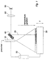
- Figure 1 is a schematic diagram of a rapid prototyping apparatus.
-
- Referring to Figure 1, a "sol" precursor solution is supplied to a nozzle or
outlet 10, from which it is sprayed onto a micro-positioning table 20 (which may comprise a conventional PZT stage and control electronics - not shown). Avoltage source 30 is used to generate an electric field between thenozzle 10 and the table 20, so that droplets of the precursor solution emerging from thenozzle 10 are attracted towards the table 20. Also, a temperature gradient is maintained (e.g. by heating elements surrounding the table 20 - not shown), so that the table is at a higher temperature than thenozzle 10. Under the influence of the temperature gradient and guided by the electric field, a sol-gel transition takes place and a gel layer is thus deposited onto the table. - Examples of suitable precursor solutions are as follows:
- Sol precursor for the deposition of stabilised zirconia (Y2O3-ZrO2)
Precursor for yttria stabilised zirconia: Y(O2C8H15)3 and Zr(OC4H9)4
Solvent: propanol or butanol - Catalyst: ethanoic acid - Sol precursor for the deposition of alumina (Al2O3):
Precursor for alumina: Al(OC4H9)3
Solvent: butanol and water - Catalyst: ethanoic acid or hydrochloric acid -
- A sol to gel transition can occur below 400°C, depending on the type of precursor and the solvent used. With the above examples, a sol to gel transition can occur between room temperature and about 250°C.
- A galvoscanner 40 (a known electrically-driven mirror capable of fine, accurate and rapid motion) causes a
laser beam 45 from a laser source 50 (focused if necessary by focusingoptics 60 shown schematically in Figure 1) the laser beam to move in the x-y direction (i.e. substantially in the plane of the table). Where the laser beam locally heats the deposited gel, that area of the gel crystallises into a ceramic material. In this way, a section of a solid object is being constructed as a result of the laser-gel interaction. In general, a coherent light source with a wavelength between ultraviolet and infrared may be used. - The galvoscanner is shown schematically, but of course would comprise (as well as at least one reflector or other directing optics such as lenses) a motor, a drive mechanism and a controller (e.g. a control computer) forming an overall drive means (not shown). In alternative embodiments, the beam could be directed by reconfiguring the relative positions of the directing optics.
- The next section is built by lowering the table in the z-direction, followed by the deposition of the gel and the scanning of the laser beam onto the selected region of the gel, to construct the desired geometry through the laser-gel interaction. The above sequence is repeated to construct a 3-D object.
- In addition, the LGM process can be applied to printing and marking applications, in which the gel material changes its optical properties (e.g. reflectivity and absorption coefficient) as a result of the laser-gel interaction, after it has been irradiated by the laser beam. The precursor used to form the gel in an electric field can be chemicals that are soluble in organic solvents or inorganic solvents. The chemicals can be natural dyes, metal alkoxides, nitrates, etc.
- The process combines the technologies of sol-gel deposition [3], deposition techniques described in our copending application [4] and laser heating. It involves the preparation of sol and subsequent spraying of the sol across an electric field under a temperature gradient onto an object forming table to produce an uniform gel deposit via a sol-gel transition induced by laser and/or other heating methods (e.g. by the temperature gradient mentioned above or by heating the nozzle 10). Subsequently, an intense laser beam is used to cause localised gel-ceramic phase transformation at selected regions of the gel deposit. A 3-D ceramic part can be constructed layer-by-layer through the manipulation of the movement of laser beam and object forming table. A 3-D computer aided design model of an engineering part is sliced into many 2-D sections. The geometries of each section are used to generate the tool paths to move the laser beam in a specific manner using a computer numerical control (CNC) system. The laser beam scans the gel deposit on the object forming table according to the tool paths, thereby forming a cross section of an engineering part via gel-ceramic transformation. The object forming table is then moved one layer down to allow the next layer of gel to be deposited and selective regions of the gel is converted into the ceramic phase at selective regions using a scanning laser beam. The 3-D part is then constructed layer-by-layer with the finest details until the final object is formed.
- The time taken to build a volume of engineering parts is influenced by the processing parameters (such as sol composition, gel deposition rate, laser energy density, laser scan speed, scan spacing and table temperature and deposition rate, etc.). This method can reduce the amount of undesirable impurities in the engineering parts because it avoids the use of binder/sintering aids to provide the mechanical strength of the part during or after building. This process can be used in atmospheric or reduced atmospheric pressure.
- Embodiments of this fabrication method can therefore combine the benefits of both laser aided transformation and the deposition processes of reference [4], offering the following advantages:
- (1) good dimensional control due to a small volume change during processing
- (2) excellent surface finish
- (3) rapid manufacture of highly dense and/or porous engineering parts
- (4) no support is required during the net shape forming process
- (5) ease of extraction of parts after the end of the manufacturing process
- (6) process can occur in open atmosphere for the production of ceramic oxide parts
- (7) application to a wide range of ceramic materials e.g. Al2O3, Y2O3-ZrO2 etc.
- (8) simple, multicomponent oxides and doped-oxides parts can be manufactured with well controlled structure and composition.
- (9) non-oxide components (such as those of metal, polymer and composites) can be manufactured in controlled atmosphere.
- (10) simple/flexible equipment
- (11) low cost and safe process using water soluble or organic soluble precursors
- (12) manufacturing process can occur at low temperatures, e.g. 300-600°C for stabilised zirconia based ceramic parts
- (13) one-step processing without the need for further heat treatment
- (14) possible to manufacture small, and precise engineering parts, as well as large engineering parts.
-
- In place of the sol precursor, aerosol or gaseous precursors could be used. In this case a similar apparatus would be used. The aerosol or gaseous precursor is passed through the nozzle or
outlet 10 and directed onto the micro-positioning table 20. The voltage source provides an electric field so that the precursor is attracted towards the table. Local heating (by the light beam) forms areas of solid stable material. This sequence is repeated to produce a 3D object. Additional heating sources can be used to heat the object if required. The approach can be used to manufacture oxide and non-oxide parts. For example, in the fabrication of B4C parts, the gaseous precursor can comprise a mixture of boron trichloride, hydrocarbon and/or hydrogen gases. The gases can also be fed separately through a coaxial cylindrical nozzle. - Besides liquid precursors, the process and apparatus of Figure 1 can also accommodate solid precursors such as powder for the manufacture of oxide and non-oxide parts. A carrier gas may be used to facilitate the transport of powder in the nozzle.
- The process is not necessarily fixed within a confined space, but can be made portable so as to allow the manufacturing of large components and/or for repairs. Thick or thin films can be deposited onto planar substrates or onto substrates with complex geometry.
- The process may be preformed in an open atmosphere for oxide materials or in a controlled atmosphere for non-oxide materials. The process can be performed at atmospheric or low pressure.
-
- [1] T Grimm, Rapid News, Vol 4(4), p48, (1996)
- [2] E A Griffin, D R Mumm and D B Marshall, American Ceramic Society Bulletin, Vol 75(7), p65 (1996)
- [3] C J Brinker and G W Scherer, Sol-Gel Science, Academic Press Inc (1990)
- [4] PCT Patent Application number PCT/GB96/03105
- [5] EP-A-0 467 097
- [6] DE-A-4 325 573
- [7] WO-A-93/20993
- [8] WO-A-93/02846
- [9] WO-A-92/16343
-
Claims (12)
- A fabrication method in which an object is formed as a plurality of successive laminae, regions of the laminae being caused to harden by application of a directable light beam (45), the method being characterised by the repeated steps of:(i) applying an aerosol or gaseous precursor onto a recipient surface;(ii) providing a temperature gradient along an application path of the precursor, so that the precursor is heated as it approaches the recipient surface and a transformation initiated so that a material layer of transformed material is deposited on the recipient surface; and(iii) locally heating regions of the material layer by directing a light beam (45) onto those regions, so that the locally-heated regions are further transformed to a solid material.
- A method according to claim 1, in which the precursor is an aerosol precursor, step (i) comprising spraying a liquid onto the recipient surface.
- A method according to any one of the preceding claims, in which the object is formed on a movable substrate (20), the method comprising the repeated step of:(iv) moving the substrate (20) so that the most recently-deposited precursor then forms a recipient surface at substantially the same position with respect to the application of precursor.
- A method according to any one of the preceding claims, in which the light beam (45) is a coherent light beam with a wavelength ranging from ultraviolet to infrared.
- A method according to claim 4, in which the light beam (45) is a laser beam.
- A method according to any one of the preceding claims, comprising the step of:applying an electric field between a precursor outlet (10) and the recipient surface, to attract the precursor towards the recipient surface.
- A method according to any one of the preceding claims, in which the precursor is an aerosol precursor comprising a sol, and in step (ii) the transformation initiated is a sol-gel transition in forming a gel material layer.
- A method according to claim 7, in which the gel material layer crystallises to form a ceramic material when heated by the light beam (45).
- Fabrication apparatus for fabricating an object as a plurality of successive laminae, the apparatus comprising:characterised by:a directable light beam (45) directable onto regions of a deposited precursor so that the regions transform to a solid material;a precursor outlet (10) for applying an aerosol or gaseous precursor onto a recipient surface; anda heater for providing a temperature gradient along an application path of the precursor, so that the precursor is heated as it approaches the recipient surface and a transformation initiated so that a material layer of transformed material is deposited on the recipient surface;whereby local heating by the light beam (45) causes regions of the material layer to be further transformed to a solid material.
- Apparatus according to claim 9, in which the object is formed on a movable substrate (20), the apparatus comprising:a substrate drive mechanism for moving the substrate (20) so that each most-recently-deposited precursor then forms a recipient surface at substantially the same position with respect to the application of precursor.
- Apparatus according to claim 9 or 10, in which the light beam (45) comprises:a light source (50);light beam directing optics (40); anda directing optics drive mechanism for moving or reconfiguring the directing optics (40) in order to direct the light beam (45).
- Apparatus according to any one of claims 9 to 11, in which the precursor is an aerosol precursor comprising a sol, and the transformation initiated is a sol-gel transition in forming a gel material layer.
Applications Claiming Priority (3)
| Application Number | Priority Date | Filing Date | Title |
|---|---|---|---|
| GBGB9702658.7A GB9702658D0 (en) | 1997-02-10 | 1997-02-10 | Fabrication method and apparatus |
| GB9702658 | 1997-02-10 | ||
| PCT/GB1998/000414 WO1998034777A1 (en) | 1997-02-10 | 1998-02-10 | Fabrication method and apparatus for fabricating an object as a plurality of successive laminae |
Publications (2)
| Publication Number | Publication Date |
|---|---|
| EP1007333A1 EP1007333A1 (en) | 2000-06-14 |
| EP1007333B1 true EP1007333B1 (en) | 2002-05-08 |
Family
ID=10807350
Family Applications (1)
| Application Number | Title | Priority Date | Filing Date |
|---|---|---|---|
| EP98903183A Expired - Lifetime EP1007333B1 (en) | 1997-02-10 | 1998-02-10 | Fabrication method and apparatus for fabricating an object as a plurality of successive laminae |
Country Status (7)
| Country | Link |
|---|---|
| US (2) | US6180186B1 (en) |
| EP (1) | EP1007333B1 (en) |
| JP (1) | JP2001511083A (en) |
| AU (1) | AU6000598A (en) |
| DE (1) | DE69805306T2 (en) |
| GB (1) | GB9702658D0 (en) |
| WO (1) | WO1998034777A1 (en) |
Families Citing this family (10)
| Publication number | Priority date | Publication date | Assignee | Title |
|---|---|---|---|---|
| DE19853947C1 (en) * | 1998-11-23 | 2000-02-24 | Fraunhofer Ges Forschung | Process chamber for selective laser fusing of material powder comprises a raised section in the cover surface above the structure volume, in which a window is arranged for the coupling in of the laser beam |
| FI20010523A0 (en) * | 2001-03-16 | 2001-03-16 | Yli Urpo Antti | Treatment of sols, gels and mixtures thereof |
| US7381633B2 (en) * | 2005-01-27 | 2008-06-03 | Hewlett-Packard Development Company, L.P. | Method of making a patterned metal oxide film |
| US7762120B2 (en) * | 2005-12-01 | 2010-07-27 | The Boeing Company | Tapered ultrasonic reference standard |
| US8113895B2 (en) * | 2005-12-16 | 2012-02-14 | Yoshihiro Watanabe | Article such as surfboard and production method thereof |
| DE102006014694B3 (en) * | 2006-03-28 | 2007-10-31 | Eos Gmbh Electro Optical Systems | Process chamber and method for processing a material with a directed beam of electromagnetic radiation, in particular for a laser sintering device |
| US8175734B2 (en) * | 2009-10-08 | 2012-05-08 | 3D M. T. P. Ltd. | Methods and system for enabling printing three-dimensional object models |
| JP6483551B2 (en) * | 2015-07-03 | 2019-03-13 | 株式会社アスペクト | Powder bed fusion unit |
| US11097532B2 (en) * | 2016-02-01 | 2021-08-24 | Ricoh Company, Ltd. | Method for making mold, method for molding model material, and mold making apparatus |
| DE102021117377A1 (en) | 2021-07-06 | 2023-01-12 | Volkswagen Aktiengesellschaft | Process for producing a separator and/or a separator layer |
Family Cites Families (12)
| Publication number | Priority date | Publication date | Assignee | Title |
|---|---|---|---|---|
| EP0542729B1 (en) * | 1986-10-17 | 1996-05-22 | Board Of Regents, The University Of Texas System | Method and apparatus for producing parts by selective sintering |
| US5352310A (en) * | 1989-02-17 | 1994-10-04 | Natter Marc D | Actinic activation shaping system and method |
| US5002854A (en) * | 1989-04-21 | 1991-03-26 | E. I. Du Pont De Nemours And Company | Solid imaging method using compositions containing core-shell polymers |
| US5156697A (en) * | 1989-09-05 | 1992-10-20 | Board Of Regents, The University Of Texas System | Selective laser sintering of parts by compound formation of precursor powders |
| US5135695A (en) * | 1989-12-04 | 1992-08-04 | Board Of Regents The University Of Texas System | Positioning, focusing and monitoring of gas phase selective beam deposition |
| US5169579A (en) * | 1989-12-04 | 1992-12-08 | Board Of Regents, The University Of Texas System | Catalyst and plasma assisted nucleation and renucleation of gas phase selective laser deposition |
| US5094935A (en) * | 1990-06-26 | 1992-03-10 | E. I. Dupont De Nemours And Company | Method and apparatus for fabricating three dimensional objects from photoformed precursor sheets |
| JP2667934B2 (en) * | 1991-05-01 | 1997-10-27 | アライド−シグナル・インコーポレーテッド | Stereolithography using vinyl ether-epoxide polymers |
| EP0640034A4 (en) * | 1992-04-15 | 1995-08-30 | Soane Technologies Inc | Rapid prototype three-dimensional stereolithography. |
| DE4325573C2 (en) * | 1993-07-30 | 1998-09-03 | Stephan Herrmann | Process for the production of moldings by successive build-up of powder layers and device for its implementation |
| US5498444A (en) * | 1994-02-28 | 1996-03-12 | Microfab Technologies, Inc. | Method for producing micro-optical components |
| US5705116A (en) * | 1994-06-27 | 1998-01-06 | Sitzmann; Eugene Valentine | Increasing the useful range of cationic photoinitiators in stereolithography |
-
1997
- 1997-02-10 GB GBGB9702658.7A patent/GB9702658D0/en active Pending
-
1998
- 1998-02-10 EP EP98903183A patent/EP1007333B1/en not_active Expired - Lifetime
- 1998-02-10 DE DE69805306T patent/DE69805306T2/en not_active Expired - Lifetime
- 1998-02-10 AU AU60005/98A patent/AU6000598A/en not_active Abandoned
- 1998-02-10 WO PCT/GB1998/000414 patent/WO1998034777A1/en active IP Right Grant
- 1998-02-10 JP JP53401698A patent/JP2001511083A/en not_active Ceased
-
1999
- 1999-08-06 US US09/371,872 patent/US6180186B1/en not_active Expired - Fee Related
-
2000
- 2000-10-27 US US09/698,620 patent/US6635112B1/en not_active Expired - Fee Related
Also Published As
| Publication number | Publication date |
|---|---|
| DE69805306D1 (en) | 2002-06-13 |
| US6180186B1 (en) | 2001-01-30 |
| GB9702658D0 (en) | 1997-04-02 |
| AU6000598A (en) | 1998-08-26 |
| US6635112B1 (en) | 2003-10-21 |
| DE69805306T2 (en) | 2002-12-05 |
| JP2001511083A (en) | 2001-08-07 |
| WO1998034777A1 (en) | 1998-08-13 |
| EP1007333A1 (en) | 2000-06-14 |
Similar Documents
| Publication | Publication Date | Title |
|---|---|---|
| Beaman et al. | Additive manufacturing review: Early past to current practice | |
| Kumar et al. | Selective laser sintering | |
| US10137636B2 (en) | Three-dimensional modelling and/or manufacturing apparatus, and related processes | |
| Bourell et al. | Solid freeform fabrication an advanced manufacturing approach | |
| US5637175A (en) | Apparatus for forming an integral object from laminations | |
| Bourell et al. | Rapid prototyping | |
| US5398193A (en) | Method of three-dimensional rapid prototyping through controlled layerwise deposition/extraction and apparatus therefor | |
| KR960008015B1 (en) | Method and apparatus for producing parts by selective sintering | |
| US5876550A (en) | Laminated object manufacturing apparatus and method | |
| US5431967A (en) | Selective laser sintering using nanocomposite materials | |
| EP1007333B1 (en) | Fabrication method and apparatus for fabricating an object as a plurality of successive laminae | |
| GB2422344A (en) | Rapid prototyping using infrared sintering | |
| Hopkinson et al. | Emerging rapid manufacturing processes | |
| WO1995030503A1 (en) | Binder compositions for selective laser sintering processes | |
| Saha et al. | Additive manufacturing of ceramics and cermets: present status and future perspectives | |
| CN1163807A (en) | Multifunctional equipment capable of fast completing various model making technique | |
| Kumar | Bed process | |
| Medelli´ n-Castillo et al. | Rapid prototyping and manufacturing: A review of current technologies | |
| WO2002042521A1 (en) | Fabrication apparatus and method | |
| Danforth et al. | Solid freeform fabrication: novel manufacturing opportunities for electronic ceramics | |
| Fateri et al. | Introduction to additive manufacturing | |
| Tang et al. | Ceramic parts fabricated by ceramic laser fusion | |
| Beaman et al. | Process methods | |
| Wang et al. | 3D printing technology and the adaptability of printing material | |
| Singh et al. | Recent Advancements in Customized Investment Castings Through Additive Manufacturing: Implication of Additive Manufacturing in Investment Casting |
Legal Events
| Date | Code | Title | Description |
|---|---|---|---|
| PUAI | Public reference made under article 153(3) epc to a published international application that has entered the european phase |
Free format text: ORIGINAL CODE: 0009012 |
|
| 17P | Request for examination filed |
Effective date: 19990907 |
|
| AK | Designated contracting states |
Kind code of ref document: A1 Designated state(s): DE FR GB IT |
|
| GRAG | Despatch of communication of intention to grant |
Free format text: ORIGINAL CODE: EPIDOS AGRA |
|
| 17Q | First examination report despatched |
Effective date: 20010118 |
|
| GRAG | Despatch of communication of intention to grant |
Free format text: ORIGINAL CODE: EPIDOS AGRA |
|
| GRAG | Despatch of communication of intention to grant |
Free format text: ORIGINAL CODE: EPIDOS AGRA |
|
| GRAH | Despatch of communication of intention to grant a patent |
Free format text: ORIGINAL CODE: EPIDOS IGRA |
|
| GRAH | Despatch of communication of intention to grant a patent |
Free format text: ORIGINAL CODE: EPIDOS IGRA |
|
| GRAH | Despatch of communication of intention to grant a patent |
Free format text: ORIGINAL CODE: EPIDOS IGRA |
|
| REG | Reference to a national code |
Ref country code: GB Ref legal event code: IF02 |
|
| GRAA | (expected) grant |
Free format text: ORIGINAL CODE: 0009210 |
|
| AK | Designated contracting states |
Kind code of ref document: B1 Designated state(s): DE FR GB IT |
|
| PG25 | Lapsed in a contracting state [announced via postgrant information from national office to epo] |
Ref country code: IT Free format text: LAPSE BECAUSE OF FAILURE TO SUBMIT A TRANSLATION OF THE DESCRIPTION OR TO PAY THE FEE WITHIN THE PRE;WARNING: LAPSES OF ITALIAN PATENTS WITH EFFECTIVE DATE BEFORE 2007 MAY HAVE OCCURRED AT ANY TIME BEFORE 2007. THE CORRECT EFFECTIVE DATE MAY BE DIFFERENT FROM THE ONE RECORDED.SCRIBED TIME-LIMIT Effective date: 20020508 Ref country code: FR Free format text: LAPSE BECAUSE OF FAILURE TO SUBMIT A TRANSLATION OF THE DESCRIPTION OR TO PAY THE FEE WITHIN THE PRESCRIBED TIME-LIMIT Effective date: 20020508 |
|
| REF | Corresponds to: |
Ref document number: 69805306 Country of ref document: DE Date of ref document: 20020613 |
|
| EN | Fr: translation not filed | ||
| PLBE | No opposition filed within time limit |
Free format text: ORIGINAL CODE: 0009261 |
|
| STAA | Information on the status of an ep patent application or granted ep patent |
Free format text: STATUS: NO OPPOSITION FILED WITHIN TIME LIMIT |
|
| 26N | No opposition filed |
Effective date: 20030211 |
|
| REG | Reference to a national code |
Ref country code: GB Ref legal event code: 746 Effective date: 20130204 |
|
| REG | Reference to a national code |
Ref country code: DE Ref legal event code: R084 Ref document number: 69805306 Country of ref document: DE Effective date: 20130612 |
|
| PGFP | Annual fee paid to national office [announced via postgrant information from national office to epo] |
Ref country code: DE Payment date: 20130829 Year of fee payment: 16 |
|
| REG | Reference to a national code |
Ref country code: DE Ref legal event code: R119 Ref document number: 69805306 Country of ref document: DE |
|
| REG | Reference to a national code |
Ref country code: DE Ref legal event code: R119 Ref document number: 69805306 Country of ref document: DE Effective date: 20140902 |
|
| PG25 | Lapsed in a contracting state [announced via postgrant information from national office to epo] |
Ref country code: DE Free format text: LAPSE BECAUSE OF NON-PAYMENT OF DUE FEES Effective date: 20140902 |
|
| PGFP | Annual fee paid to national office [announced via postgrant information from national office to epo] |
Ref country code: GB Payment date: 20170227 Year of fee payment: 20 |
|
| REG | Reference to a national code |
Ref country code: GB Ref legal event code: PE20 Expiry date: 20180209 |
|
| PG25 | Lapsed in a contracting state [announced via postgrant information from national office to epo] |
Ref country code: GB Free format text: LAPSE BECAUSE OF EXPIRATION OF PROTECTION Effective date: 20180209 |