EP1007296B1 - Apparatus for shielding an articulated structure - Google Patents
Apparatus for shielding an articulated structure Download PDFInfo
- Publication number
- EP1007296B1 EP1007296B1 EP98934719A EP98934719A EP1007296B1 EP 1007296 B1 EP1007296 B1 EP 1007296B1 EP 98934719 A EP98934719 A EP 98934719A EP 98934719 A EP98934719 A EP 98934719A EP 1007296 B1 EP1007296 B1 EP 1007296B1
- Authority
- EP
- European Patent Office
- Prior art keywords
- shielding
- sections
- cavity
- section
- joint
- Prior art date
- Legal status (The legal status is an assumption and is not a legal conclusion. Google has not performed a legal analysis and makes no representation as to the accuracy of the status listed.)
- Expired - Lifetime
Links
Images



Classifications
-
- B—PERFORMING OPERATIONS; TRANSPORTING
- B25—HAND TOOLS; PORTABLE POWER-DRIVEN TOOLS; MANIPULATORS
- B25J—MANIPULATORS; CHAMBERS PROVIDED WITH MANIPULATION DEVICES
- B25J19/00—Accessories fitted to manipulators, e.g. for monitoring, for viewing; Safety devices combined with or specially adapted for use in connection with manipulators
- B25J19/0075—Means for protecting the manipulator from its environment or vice versa
- B25J19/0079—Means for protecting the manipulator from its environment or vice versa using an internal pressure system
-
- B—PERFORMING OPERATIONS; TRANSPORTING
- B25—HAND TOOLS; PORTABLE POWER-DRIVEN TOOLS; MANIPULATORS
- B25J—MANIPULATORS; CHAMBERS PROVIDED WITH MANIPULATION DEVICES
- B25J19/00—Accessories fitted to manipulators, e.g. for monitoring, for viewing; Safety devices combined with or specially adapted for use in connection with manipulators
- B25J19/0075—Means for protecting the manipulator from its environment or vice versa
- B25J19/0083—Means for protecting the manipulator from its environment or vice versa using gaiters
-
- Y—GENERAL TAGGING OF NEW TECHNOLOGICAL DEVELOPMENTS; GENERAL TAGGING OF CROSS-SECTIONAL TECHNOLOGIES SPANNING OVER SEVERAL SECTIONS OF THE IPC; TECHNICAL SUBJECTS COVERED BY FORMER USPC CROSS-REFERENCE ART COLLECTIONS [XRACs] AND DIGESTS
- Y10—TECHNICAL SUBJECTS COVERED BY FORMER USPC
- Y10T—TECHNICAL SUBJECTS COVERED BY FORMER US CLASSIFICATION
- Y10T137/00—Fluid handling
- Y10T137/6851—With casing, support, protector or static constructional installations
- Y10T137/7043—Guards and shields
-
- Y—GENERAL TAGGING OF NEW TECHNOLOGICAL DEVELOPMENTS; GENERAL TAGGING OF CROSS-SECTIONAL TECHNOLOGIES SPANNING OVER SEVERAL SECTIONS OF THE IPC; TECHNICAL SUBJECTS COVERED BY FORMER USPC CROSS-REFERENCE ART COLLECTIONS [XRACs] AND DIGESTS
- Y10—TECHNICAL SUBJECTS COVERED BY FORMER USPC
- Y10T—TECHNICAL SUBJECTS COVERED BY FORMER US CLASSIFICATION
- Y10T137/00—Fluid handling
- Y10T137/8593—Systems
- Y10T137/86268—With running joint between movable parts of system
Definitions
- the present invention relates to protective coverings for use in industrial operations to be carried out in hard working environment, and more particularly to protective apparatus for covering an articulated structure such as a robot arm.
- An apparatus for shielding according to the preamble of claim 1 and a shielded apparatus according to the preamble of claim 5 are known from EP-A-0 138 461.
- a shielded apparatus for working in hard environment comprising a movable articulated structure including at least two segments connected through an articulation to allow movement of at least one of the segments through drive means connected to control means, at least a portion of the articulated structure having to be protected against contamination from the working environment.
- the apparatus further comprises at least first and second sections for shielding outer surfaces of said at least one movable segment and the articulation as part of said structure portion, at least one of the first and second shielding sections defining with corresponding said outer surface a cavity therebetween.
- the apparatus also comprises gas input means adapted to be connected to a supply of inactive gas for filling the cavity and gas input means adapted to be connected to a supply of inactive gas for filling the cavity.
- the apparatus is characterized in that the first and second sections are rigidly connected at respective ends thereof to the movable segment and the articulation respectively in a such manner to mate at respective second ends of the sections in a close spaced relationship to form a substantially contactless joint permitting relative rotational movement of the sections, wherein the joint provides escape of the inactive gas out of the cavity while maintaining within the cavity a positive gas pressure relative to environment ambient pressure sufficient to substantially prevent contamination of the structure portion from the working environment.
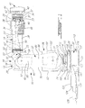
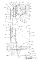
- the apparatus 10 comprises a first shielding or cover section 14 for covering the front arm segment 16 of the robot arm 12, a second shielding or cover section 18 for partially covering an upper pivoting articulation 20, a third shielding or cover section 22 for covering a middle arm segment 24 of the robot arm 12 and a fourth shielding or cover section 26 for covering a lower pivoting articulation 28 of the robot arm 12.
- the robot arm 12 stands on a mounting ring 30 secured to a fixed base 32.
- the first shielding section 14 comprises an end rotating portion 34, a pivoting portion 36 and a rear rotating portion 38.
- the end portion 34 in the form of bellows, is provided for covering a safety clutch (not shown) of a conventional construction being coupled to a mounting disk 40 to which is secured a head 41 holding a working element or tool 44, which is a dual-blade meat cutting tool in the example shown in Figs. 1-3.
- the front end edge 37 of the end portion bellows 34 is tightly attached to the mounting disk 40 through a proper gastight and impermeable adhesive.
- the safety clutch is caused to be released whenever the tool 44 runs against an obstacle, thereby preventing or limiting damage either to the robot or obstacle.
- the rear rotating portion 38 is formed with a generally cylindrical shape and has a front end edge 43 adapted to be tightly connected to a rear end edge 33' of the pivoting portion bellows 36, through use of a proper gastight and impermeable adhesive.
- the rear end 43' of the rear rotating portion 38 is in turn coupled in a close mating relationship to a front cylindrical end portion 25 of the second shielding section 18 through a second rotary joint 52, which will be later described in more detail with reference to Fig. 6.
- the front arm section 16 of the robot arm 12 comprises a rear rotating articulation formed by a rotating portion 53 and a fixed portion 55 secured to the upper pivoting articulation 20.
- the cylindrical end portion 25 of the second shielding section 18 is tightly attached to a main portion 54 thereof formed by a tight assembly of top wall 56, side walls 57, 57', front wall 58 and bottom wall 60.
- a diagonally extending rear wall 62 is tightly attached to outer edges of walls 57, 57' 56 and 60 through proper fasteners 66 to form a closed cavity containing a protected portion of the upper pivoting articulation 20, which also comprises an articulation portion 64 which is was already sealed at the robot arm manufacturing stage, as better shown in Fig. 3.
- the sealed articulation portion 64 which includes the pivoting actuator casing 68, does not require to be further shielded, thereby providing direct access thereto for maintenance, the shielding section 18 may be designed to entirely cover the upper pivoting articulation 20.
- the shielding section 18 is further provided with a side cylindrical portion 70 having an inner side edge 72 tightly attached to the side wall 57, and having an outer side edge 72' being coupled in a close mating relationship to an upper inner side edge 74 of the third shielding section 22 covering the middle arm segment 24 through a third rotary joint 82, which will be later described in more detail with reference to Fig. 7.
- the third shielding section 22 is formed by a tight assembly of peripheral wall 76, inner side wall 78 and outer side wall 80.
- a generally circular upper opening 84 is provided in the outer side wall 80, the edge of which opening 84 being tightly attached to another side edge of the rotary joint 82, as will be explained with reference to Fig. 7.
- a second opposed opening 84 is provided in the outer side wall 78 to give access to the upper pivoting articulation 20 by withdrawing a cover plate tightly affixed to the outer side wall 78 through fasteners 90.
- a lower inner side edge 91 of the third shielding section 22 defines an opening 93 being coupled in a close mating relationship through a fourth rotary joint 94, which will be later described in more with reference to Fig. 8, to an inner side wall 92 as part of the fourth shielding section 26 covering the lower pivoting articulation 28 of the robot arm 12, as better shown in Fig. 2.
- the fourth shielding section 26 further comprises a bottom wall 96 to which are tightly attached top wall 98, outer side wall 92', front wall 100 and rear wall 102. As shown in Fig.
- the mounting ring 30 is provided with a flanged portion 116 being firmly secured to the fixed robot base 32, provided with shielding casing or cover 118 having a top wall 120 provided with a main opening 123 though which upwardly extends the rotating frame 106, as better seen in Fig. 2.
- the shielding casing 118 further has a front wall 122, rear wall 124, bottom wall 125 and side walls 126, 126'.
- the shielding casing 118 communicates with a duct 128 containing line 130 through which electric power, pneumatic and/or hydraulic power are supplied to the robot arm 12.
- the duct 128 is also used to supply the casing 118 and the shielding sections 14, 18, 22 with pressurized gas, which is air as produced by a conventional blower unit 132 in an example shown in Fig. 4, which draws air from a controlled atmosphere location.
- the pressurized inactive gas provides positive gas pressure, relative to ambient environment pressure, within communicating cavities formed between inner surface of shielding sections 14, 18, 22, 26 and outer surface of the corresponding robot arm segments 16, 20, 24 , 28.
- the joints 35, 52, 82 and 94 are designed to allow escape the pressurized gas out of the communicating cavities, while maintaining within the cavities a gas pressure sufficient to prevent contamination of the covered arm portion from the working environment, either in operation or during washing.
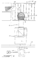
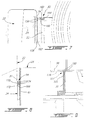
- the rotary joint 35 comprises a first flanged ring 140 to which the front end edge 33 of the pivoting portion 36 is tightly attached, the ring 140 having an outer race plane surface 141 and being secured to the body of the rotary actuator 39.
- the joint 35 further comprises a second ring 142 having an inner race surface 143 and being tightly affixed to the rear edge 37' of the shielding portion 34 and secured to the safety clutch body (not shown).
- the inner race surface 143 is provided with a plurality of concentric circular ribs 144 defining a plurality of grooves forming a labyrinth.
- Relative position of first and second rings 140 and 142 are adjusted to provide minimal spacing between the inner race ribs and the outer race surface, to avoid physical contact therebetween.
- the minimum spacing that can be achieved mostly relies on manufacturing tolerances of the joint components, which can be typically within about 0.002 - 0.003 inch range (0,005-0,0076 cm).
- Inactive gas turbulence occurring through the successive ribs and grooves yields to maintain a pressure gradient between the shielding cavity and the outside environment, without the need of physical sealing contact.
- Optimum minimal spacing is achieved when desired positive pressure regulation is obtained.
- Use of such labyrinth seal has an advantage of minimizing torque required to rotate mating portions of the shielding section, reducing maintenance due to parts wearing. It is to be understood that only a portion of the circular inner race surface 143 of the second ring 142 can be provided with contactless ribs 144, provided desired positive pressure regulation is obtained.
- the rotary joint 52 comprises a first ring 146 having an outer race plane surface 148 an to which a front cylindrical end portion 25 of the second shielding section 18 is tightly attached, the ring 146 being secured to the fixed portion 55 of the rear rotating articulation of the front arm section 16.
- the joint 52 further comprises a second ring 150 having an inner race surface 152 and being tightly affixed to the rear edge 43' of the shielding portion 14 with a collar 154, the ring 150 being rigidly secured to the rotating portion 53.
- the inner race surface 152 is provided with a plurality of concentric circular ribs 156 defining a plurality of grooves forming a labyrinth, as described before.
- the rotary joint 94 uses the inner side wall 92 which is part of the fourth shielding section 26 to provide an outer race plane surface 168.
- the joint 94 comprises a ring 170 having an inner race surface 172 and being tightly affixed to the lower inner side edge 91 of the third shielding section 22, and being rigidly secured to the middle arm segment 24.
- the inner race surface 172 is provided with a plurality of concentric circular ribs 174 defining a plurality of grooves forming a labyrinth, as described before.
- upper edge 105 of the mounting ring 30 forms with the underneath surface 176 of the bottom wall 96 the fifth rotary joint 107, using the underneath surface 176 as an outer race surface and the ring upper edge 105 as an inner race surface through a pair of concentric circular ribs 180 defining a groove forming a labyrinth, as described before.
- the blower unit shown in Fig. 4 draws air from the controlled atmosphere of the room 134 to produce a flow of pressurized air through the line 128 for air feeding the shielding casing 118.
- Input flow of air designated by arrow 182 fills the inner cavity of the casing 118 to pass through the mounting ring, with a small portion of air flow escaping through the joint 107 as better shown in Fig. 2 and as explained before.
- Passing through an aperture in bottom wall, the flow of air fills the fourth shielding section 26 to reach the third shielding section 22 for filling thereof, with a small portion of air flow escaping through the joint 94 as explained before.
- the flow of air then passes through the side cylindrical portion 70 of the second shielding section 18 for filling thereof, with a small portion of air flow escaping through the joint 82 as explained before. Finally, the flow of air fills the first shielding section 14, with a small portion of air flow escaping through the joints 52 and 35. It is to be understood that an equilibrium state is rapidly reached when mean pressure equal to the desired positive pressure is attained at the optimal extension of the shielding portion made of flexible material, where the air input flow rate is equal to the sum of the air output flows escaping the joints 107, 94, 82, 52 and 35.
- the robot system provided with the shielding apparatus 10 is then ready to operate in a hard working environment, being substantially protected against contamination from substances such as dust, explosive gas or vapor, corrosive cleaning fluid, etc.
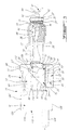
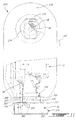
- the shielding apparatus 210 shown is used to cover a robot arm illustrated in dashed lines and generally designated at 212, which is of a same type than the robot arm described before with reference to the first preferred embodiment.
- the apparatus 210 comprises a first shielding or cover section 214 for covering the front arm segment 16 of the robot arm 12 as shown in Fig. 12.
- the apparatus 210 further comprises a second shielding or cover section 218 for completely covering the upper pivoting articulation 20, the middle arm segment 24 and the lower pivoting articulation 28 of the robot arm 12.
- the robot arm 12 stands on a mounting ring 230 secured to a fixed base 232.
- the rear end 243' of the rear portion 238 is in turn tightly attached to edge 253 of an aperture defined in an upper portion of the second shielding section 218.
- the rear portion 238 and the second section 218 are also made of a material showing sufficient flexibility to allow rotation movement of the front arm segment 16 within a working rotation angle range. It is to be understood that the end portion 234 can be designed in a similar way without use of the rotary joint 235 for limited working rotating angle range of the tool 244, through direct tight attachment to the safety clutch body.
- the second shielding section 218 further comprises a bottom wall 296 provided with a main opening 204 though which the rotating frame 106 as part of the robot arm 12 extends upwardly, as shown in Fig. 10.
- Upper edge 305 of the mounting ring 30 forms with the underneath surface of the bottom wall 296 a second rotary joint 307, of a similar construction as the joint illustrated in Fig. 9 and as described before. It is to be understood that the second section 218 can be designed in a similar way than rear portion 238 without use of the rotary joint 307 for limited working rotating angle range of the rotating frame 106, through direct tight attachment to the mounting ring 30.
- the bottom wall 296 is further provided with small openings to provide sealed installation of a rotation stopper 108, and as explained before. As shown in Fig.
- the duct 128 is also used to supply the casing 318 and the shielding sections 314 and 318 with pressurized inactive gas, which is air as produced by a conventional blower as the one shown in Fig. 4.
- the pressurized inactive gas fills the communicating cavities formed between inner surface of shielding sections 314 and 318 and outer surface of the corresponding robot arm segments 16, 20, 24, 28, providing positive gas pressure within relative to ambient environment pressure.
- the first and second cover sections 214 and 218 being essentially made of a substantially gastight and impermeable flexible material which is sufficiently stiff to provide the cover section with sufficiently smooth and stiff outer surface under sufficient positive pressure, to substantially prevent physical contact between the segment outer surface and the cover section which could result in cover damage.
- the cover sections have sufficient area to provide cavities with sufficient volume to allow robot arm movement within its working range without requiring adverse stretching of the material.
- the joints 235 and 307 are designed to allow escape the pressurized gas out of the communicating cavities, while maintaining within the cavities a gas pressure sufficient to extend the sections 314 and 318 to their working shapes, while preventing contamination of the covered arm portion from the working environment, either in operation or during washing. It is to be understood that any of the cavities associated with any portions of shielding sections 214 and 218 can be independently supplied with a separate gas feeding line, and that only one of the joint 235 and 307 can be designed to allow gas escape, provided the positive pressure is maintained under the maximum pressure rating the shielding material can take without being damaged.
- an optional gas regulating valve 300 of a conventional construction as illustrated in dotted line in Fig. 11 can be used to obtain the desired positive pressure.
- Extendible materials as listed before can be used to form the required shapes for the portions 234, 236, 238 of section 214 and for section 218. It is to be understood that any other suitable gastight and impermeable material showing sufficient flexibility can be used.
- Other sealing techniques not using adhesive can be also employed depending upon the material used, such as heat or high frequency sealing techniques.
- FIG. 4 draws air from the controlled atmosphere of the room 134 to produce a flow of pressurized air through the line 128 for air feeding the shielding casing 318.
- Input flow of air designated by arrow 182 fills the inner cavity of the casing 318 to pass through the mounting ring, with a small portion of air flow escaping through the joint 307 as better shown in Fig. 2 and as explained before.
Landscapes
- Engineering & Computer Science (AREA)
- Robotics (AREA)
- Mechanical Engineering (AREA)
- Manipulator (AREA)
Description
Claims (8)
- An apparatus (10) for shielding at least a portion of a movable articulated structure (12) including at least two segments (16,24) connected through an articulation (20) to allow movement of at least one of said segments (16), the structure portion having to be protected against contamination from a working environment, said apparatus comprising:wherein, in use, said joint (52) provides escape of the inactive gas out of the cavity while maintaining within the cavity a positive gas pressure relative to environment ambient pressure sufficient to substantially prevent contamination of the structure portion from the working environment.at least first and second sections (14,18) for shielding outer surfaces of said at least one movable segment (16) and said articulation (20) as part of said structure portion, at least one of said first and second shielding sections (14,18) defining with corresponding said outer surface a cavity therebetween; andgas input means (128) adapted to be connected to a supply (132) of inactive gas for filling the cavity;the apparatus being characterized in that the first and second sections (14,18) being rigidly connectable to said movable segment (16) and said articulation (20) respectively in a such manner to mate at respective ends (43',25) of said sections in a close spaced relationship to form a substantially contactless joint (52) permitting relative rotational movement of said sections (14,18);
- An apparatus as claimed in claim 1, wherein said joint is a labyrinth joint.
- An apparatus as claimed in claim 1, wherein said section (14) defining the cavity is essentially made of a substantially gas-tight and impermeable flexible material which is sufficiently stiff to provide the section (14) with sufficiently smooth and stiff outer surface under said positive pressure, to substantially prevent physical contact between said segment outer surface and the section which could result in section damage.
- An apparatus as claimed in claim 3, wherein said apparatus further comprises a gas pressure regulating output valve (300).
- A shielded apparatus (10) for working in hard environment comprising:wherein, in use, said joint (52) provides escape of the inactive gas out of the cavity while maintaining within the cavity a positive gas pressure relative to environment ambient pressure sufficient to substantially prevent contamination of the structure portion from the working environment.a movable articulated structure (12) including at least two segments (16,24) connected through an articulation (20) to allow movement of at least one of said segments (16) through drive means (68) connected to control means (131), at least a portion of said articulated structure (12) having to be protected against contamination from the working environment;at least first and second sections (14,18) for shielding outer surfaces of said at least one movable segment (16) and said articulation (20) as part of said structure portion, at least one of said first and second shielding sections (14,18) defining with corresponding said outer surface a cavity therebetween; andgas input means (128) adapted to be connected to a supply (132) of inactive gas for filling the cavity;the apparatus (10) being characterized in that the first and second sections (14,18) are rigidly connected to said movable segment (16) and said articulation (20) respectively in a such manner to mate at respective ends (43',25) of said sections in a close spaced relationship to form a substantially contactless joint (52) permitting relative rotational movement of said sections (14, 18) ;
- An apparatus as claimed in claim 5, wherein said joint is a labyrinth joint.
- An apparatus as claimed in claim 5, wherein said section (14) defining the cavity is essentially made of a substantially gas-tight and impermeable flexible material which is sufficiently stiff to provide the section with sufficiently smooth and stiff outer surface under said positive pressure, to substantially prevent physical contact between said outer segment surface and the section which could result in section damage.
- An apparatus as claimed in claim 7, wherein said apparatus further comprises a gas pressure regulating output valve (300).
Applications Claiming Priority (3)
| Application Number | Priority Date | Filing Date | Title |
|---|---|---|---|
| CA2213287 | 1997-08-18 | ||
| CA002213287A CA2213287A1 (en) | 1997-08-18 | 1997-08-18 | Apparatus for shielding an articulated structure |
| PCT/CA1998/000706 WO1999008841A1 (en) | 1997-08-18 | 1998-07-20 | Apparatus for shielding an articulated structure |
Publications (2)
| Publication Number | Publication Date |
|---|---|
| EP1007296A1 EP1007296A1 (en) | 2000-06-14 |
| EP1007296B1 true EP1007296B1 (en) | 2002-11-13 |
Family
ID=4161284
Family Applications (1)
| Application Number | Title | Priority Date | Filing Date |
|---|---|---|---|
| EP98934719A Expired - Lifetime EP1007296B1 (en) | 1997-08-18 | 1998-07-20 | Apparatus for shielding an articulated structure |
Country Status (7)
| Country | Link |
|---|---|
| US (1) | US6039068A (en) |
| EP (1) | EP1007296B1 (en) |
| JP (1) | JP2001514978A (en) |
| AU (1) | AU8428798A (en) |
| CA (1) | CA2213287A1 (en) |
| DE (1) | DE69809440T2 (en) |
| WO (1) | WO1999008841A1 (en) |
Families Citing this family (25)
| Publication number | Priority date | Publication date | Assignee | Title |
|---|---|---|---|---|
| US6346150B1 (en) * | 1998-06-19 | 2002-02-12 | Douglas Conlin | Paint spray booth with robot |
| JP2000141270A (en) * | 1998-11-06 | 2000-05-23 | Matsushita Electric Ind Co Ltd | Articulated robot |
| US6279412B1 (en) * | 1999-05-19 | 2001-08-28 | Brooks Automation, Inc. | Corrosion resistant exoskeleton arm linkage assembly |
| EP1215683A3 (en) * | 2000-11-20 | 2003-05-21 | Framatome ANP | Segmented link robot for waste removal |
| US6543307B2 (en) * | 2001-04-06 | 2003-04-08 | Metrica, Inc. | Robotic system |
| US6598502B1 (en) * | 2002-01-28 | 2003-07-29 | Titan Technologies International, Inc. | Multi-swivel connector for a fluid operated tool |
| US7238079B2 (en) * | 2003-01-14 | 2007-07-03 | Disney Enterprise, Inc. | Animatronic supported walking system |
| DE10350801A1 (en) * | 2003-10-29 | 2005-06-16 | Kuka Roboter Gmbh | Handling device, in particular for the food industry |
| DE10357609A1 (en) | 2003-12-10 | 2005-07-21 | Kuka Roboter Gmbh | Handling device such as industrial robots and method for influencing an environmental condition in such |
| CN102079094B (en) * | 2009-11-26 | 2013-11-06 | 鸿富锦精密工业(深圳)有限公司 | Robot structure |
| DE102008005901B4 (en) * | 2008-01-24 | 2018-08-09 | Deutsches Zentrum für Luft- und Raumfahrt e.V. | Sterile barrier for a surgical robot with torque sensors |
| DE102008059505A1 (en) * | 2008-11-28 | 2010-06-02 | Dürr Systems GmbH | Protective cover for dirt protection of a robot |
| US20110154929A1 (en) * | 2009-12-30 | 2011-06-30 | United Microelectronics Corp. | Wafer transfer apparatus and shielding mechanism |
| WO2011107143A1 (en) * | 2010-03-02 | 2011-09-09 | Abb Research Ltd | A robot wrist |
| US20120055595A1 (en) * | 2010-09-02 | 2012-03-08 | Robert Schodowski | Robot cover |
| DE102011121017A1 (en) * | 2011-12-13 | 2013-06-13 | Weber Maschinenbau Gmbh Breidenbach | Device for processing food products |
| FR3015334B1 (en) * | 2013-12-23 | 2017-02-10 | Electricite De France | ROTARY ANNULAR CONNECTOR FOR ENVELOPE FOR PROTECTING AN ARTICULATED ROBOT ARM |
| FR3015335B1 (en) * | 2013-12-23 | 2016-01-08 | Electricite De France | SLEEVE FOR PROTECTING AN ARTICULATED ROBOT ARM AND METHOD FOR MANUFACTURING THE SAME |
| JP6538498B2 (en) * | 2015-09-15 | 2019-07-03 | ファナック株式会社 | Robot with a wrist having a hollow movable element and a waterproof structure |
| JP2019111587A (en) * | 2016-04-27 | 2019-07-11 | ライフロボティクス株式会社 | Joint mechanism |
| EP3548230B1 (en) * | 2016-12-05 | 2023-07-12 | ABB Schweiz AG | Sealing arrangement for use in robot joint |
| US11007636B2 (en) | 2017-03-31 | 2021-05-18 | Kinova Inc. | Articulated mechanism with protective sleeve at joint |
| CN106826806A (en) * | 2017-04-13 | 2017-06-13 | 云南电网有限责任公司电力科学研究院 | A kind of industrial robot for X-ray detection |
| CN110877348A (en) * | 2018-09-06 | 2020-03-13 | 上海吾问机器人应用科技有限公司 | High and low temperature resistant industrial robot |
| DE102021104378A1 (en) * | 2021-02-24 | 2022-08-25 | Dürr Systems Ag | Protective cover for a robot wrist axis |
Family Cites Families (16)
| Publication number | Priority date | Publication date | Assignee | Title |
|---|---|---|---|---|
| US3620253A (en) * | 1969-04-30 | 1971-11-16 | Filton Ltd | Rotary distributor |
| WO1985001496A1 (en) * | 1983-10-03 | 1985-04-11 | American Telephone & Telegraph Company | Protective robot covering |
| JPS6133890A (en) * | 1984-07-26 | 1986-02-17 | 松下電器産業株式会社 | industrial robot |
| US4984745A (en) | 1985-01-22 | 1991-01-15 | Gmf Robotics Corporation | Electric robot for use in a hazardous location |
| FR2583817B1 (en) | 1985-06-20 | 1988-07-29 | Snecma | TURBOMACHINE COMPRESSOR VARIABLE TIMING BLADE DRIVE CONTROL LINK |
| US4668146A (en) | 1985-10-25 | 1987-05-26 | Kabushiki Kaisha Kobe Seiko Sho | Explosion proof construction of motor robot |
| GB2191827A (en) * | 1986-06-23 | 1987-12-23 | British Nuclear Fuels Plc | Master/slave manipulators |
| JPS6365973A (en) * | 1986-09-05 | 1988-03-24 | Hitachi Ltd | robot equipment |
| US4904514A (en) | 1988-09-13 | 1990-02-27 | Kimberly-Clark Corporation | Protective covering for a mechanical linkage |
| JPH0283192A (en) * | 1988-09-20 | 1990-03-23 | Tokico Ltd | industrial robot |
| US5065062A (en) * | 1988-10-20 | 1991-11-12 | Tokico Ltd. | Motor-drive industrial robot |
| US5212432A (en) | 1989-10-20 | 1993-05-18 | Tokico, Ltd. | Industrial robot |
| US5054523A (en) * | 1990-03-23 | 1991-10-08 | Unidynamics Corporation | Containment system for flexible underground piping |
| FR2683479B1 (en) * | 1991-11-07 | 1996-02-09 | Innovations Tech | DEVICE FOR ROTATING AND SEALING CONNECTION OF A PROTECTIVE BELLOWS ON THE END OF A SLAVE TELEMANIPULATOR ARM. |
| US5440916A (en) | 1993-11-15 | 1995-08-15 | The United States Of America As Represented By The Administrator Of The National Aeronatics And Space Administration | Emergency response mobile robot for operations in combustible atmospheres |
| US5772520A (en) * | 1996-07-11 | 1998-06-30 | Ford Motor Company | Vented studyoke on slip-between-center driveshaft |
-
1997
- 1997-08-18 CA CA002213287A patent/CA2213287A1/en not_active Abandoned
-
1998
- 1998-07-20 EP EP98934719A patent/EP1007296B1/en not_active Expired - Lifetime
- 1998-07-20 WO PCT/CA1998/000706 patent/WO1999008841A1/en not_active Ceased
- 1998-07-20 DE DE69809440T patent/DE69809440T2/en not_active Expired - Fee Related
- 1998-07-20 JP JP2000509562A patent/JP2001514978A/en active Pending
- 1998-07-20 AU AU84287/98A patent/AU8428798A/en not_active Abandoned
- 1998-07-22 US US09/120,823 patent/US6039068A/en not_active Expired - Fee Related
Also Published As
| Publication number | Publication date |
|---|---|
| US6039068A (en) | 2000-03-21 |
| JP2001514978A (en) | 2001-09-18 |
| WO1999008841A1 (en) | 1999-02-25 |
| AU8428798A (en) | 1999-03-08 |
| DE69809440T2 (en) | 2003-10-02 |
| DE69809440D1 (en) | 2002-12-19 |
| EP1007296A1 (en) | 2000-06-14 |
| CA2213287A1 (en) | 1999-02-18 |
Similar Documents
| Publication | Publication Date | Title |
|---|---|---|
| US6039068A (en) | Apparatus for shielding an articulated structure | |
| CN107000222B (en) | Industrial robot and method for moving a robotic arm in a clean room | |
| EP0169554B1 (en) | Industrial robot | |
| EP1075206A1 (en) | A system for treating exterior surfaces | |
| US20060104792A1 (en) | Manipulator with a line arrangement leading to the processing tool | |
| US20200376686A1 (en) | Robot arm having at least one deformation element | |
| CN110405728A (en) | Parallel Link Robot | |
| Stilwell et al. | Optimal control for cooperating mobile robots bearing a common load | |
| EP0710157B1 (en) | Robot installation installed in a painting cabin | |
| KR101539910B1 (en) | Dual-arm Assistance Device for Part Assembly in Human Cooperation | |
| JPS6263088A (en) | Dustroof liquid-preventive structure of industrial robot | |
| Pohl et al. | A new method of robotic rate control near singularities | |
| US6346150B1 (en) | Paint spray booth with robot | |
| CN111918720B (en) | Operation cover | |
| US5893567A (en) | Sealing system for sealing an opening | |
| GB2279429A (en) | Valve assembly with cleaning means | |
| GB2352989A (en) | Extrusion nozzle | |
| US20040187989A1 (en) | Robot cover | |
| JP2020537597A (en) | Suction for grinding tools with radial brush plates | |
| EP1314484A1 (en) | Spray booth | |
| US20260035188A1 (en) | Transport apparatus for containers, and system for processing containers | |
| JPH0253581A (en) | Industrial robot equipped with horizontal arm | |
| CN221086099U (en) | Spraying protection device for spraying robot | |
| TW202333918A (en) | Parallel link robot | |
| WO2020053820A1 (en) | Device and method for gripping objects |
Legal Events
| Date | Code | Title | Description |
|---|---|---|---|
| PUAI | Public reference made under article 153(3) epc to a published international application that has entered the european phase |
Free format text: ORIGINAL CODE: 0009012 |
|
| 17P | Request for examination filed |
Effective date: 20000211 |
|
| AK | Designated contracting states |
Kind code of ref document: A1 Designated state(s): DE FR GB IT |
|
| GRAG | Despatch of communication of intention to grant |
Free format text: ORIGINAL CODE: EPIDOS AGRA |
|
| 17Q | First examination report despatched |
Effective date: 20020207 |
|
| GRAG | Despatch of communication of intention to grant |
Free format text: ORIGINAL CODE: EPIDOS AGRA |
|
| GRAH | Despatch of communication of intention to grant a patent |
Free format text: ORIGINAL CODE: EPIDOS IGRA |
|
| GRAH | Despatch of communication of intention to grant a patent |
Free format text: ORIGINAL CODE: EPIDOS IGRA |
|
| GRAA | (expected) grant |
Free format text: ORIGINAL CODE: 0009210 |
|
| AK | Designated contracting states |
Kind code of ref document: B1 Designated state(s): DE FR GB IT |
|
| PG25 | Lapsed in a contracting state [announced via postgrant information from national office to epo] |
Ref country code: IT Free format text: LAPSE BECAUSE OF FAILURE TO SUBMIT A TRANSLATION OF THE DESCRIPTION OR TO PAY THE FEE WITHIN THE PRESCRIBED TIME-LIMIT;WARNING: LAPSES OF ITALIAN PATENTS WITH EFFECTIVE DATE BEFORE 2007 MAY HAVE OCCURRED AT ANY TIME BEFORE 2007. THE CORRECT EFFECTIVE DATE MAY BE DIFFERENT FROM THE ONE RECORDED. Effective date: 20021113 |
|
| REG | Reference to a national code |
Ref country code: GB Ref legal event code: FG4D |
|
| REF | Corresponds to: |
Ref document number: 69809440 Country of ref document: DE Date of ref document: 20021219 |
|
| PGFP | Annual fee paid to national office [announced via postgrant information from national office to epo] |
Ref country code: FR Payment date: 20030619 Year of fee payment: 6 |
|
| PGFP | Annual fee paid to national office [announced via postgrant information from national office to epo] |
Ref country code: GB Payment date: 20030630 Year of fee payment: 6 |
|
| ET | Fr: translation filed | ||
| PGFP | Annual fee paid to national office [announced via postgrant information from national office to epo] |
Ref country code: DE Payment date: 20030708 Year of fee payment: 6 |
|
| RAP2 | Party data changed (patent owner data changed or rights of a patent transferred) |
Owner name: INTELLIUM AUTOMATION INC. |
|
| PLBE | No opposition filed within time limit |
Free format text: ORIGINAL CODE: 0009261 |
|
| STAA | Information on the status of an ep patent application or granted ep patent |
Free format text: STATUS: NO OPPOSITION FILED WITHIN TIME LIMIT |
|
| 26N | No opposition filed |
Effective date: 20030814 |
|
| PG25 | Lapsed in a contracting state [announced via postgrant information from national office to epo] |
Ref country code: GB Free format text: LAPSE BECAUSE OF NON-PAYMENT OF DUE FEES Effective date: 20040720 |
|
| PG25 | Lapsed in a contracting state [announced via postgrant information from national office to epo] |
Ref country code: DE Free format text: LAPSE BECAUSE OF NON-PAYMENT OF DUE FEES Effective date: 20050201 |
|
| GBPC | Gb: european patent ceased through non-payment of renewal fee |
Effective date: 20040720 |
|
| PG25 | Lapsed in a contracting state [announced via postgrant information from national office to epo] |
Ref country code: FR Free format text: LAPSE BECAUSE OF NON-PAYMENT OF DUE FEES Effective date: 20050331 |
|
| REG | Reference to a national code |
Ref country code: FR Ref legal event code: ST |