EP1005646B1 - Housing for a flammable gas detector - Google Patents
Housing for a flammable gas detector Download PDFInfo
- Publication number
- EP1005646B1 EP1005646B1 EP98939739A EP98939739A EP1005646B1 EP 1005646 B1 EP1005646 B1 EP 1005646B1 EP 98939739 A EP98939739 A EP 98939739A EP 98939739 A EP98939739 A EP 98939739A EP 1005646 B1 EP1005646 B1 EP 1005646B1
- Authority
- EP
- European Patent Office
- Prior art keywords
- housing
- sinter
- flammable gas
- around
- gas detector
- Prior art date
- Legal status (The legal status is an assumption and is not a legal conclusion. Google has not performed a legal analysis and makes no representation as to the accuracy of the status listed.)
- Expired - Lifetime
Links
- 239000004033 plastic Substances 0.000 claims description 25
- 229920003023 plastic Polymers 0.000 claims description 25
- 239000000463 material Substances 0.000 claims description 20
- 239000000843 powder Substances 0.000 claims description 10
- 238000000034 method Methods 0.000 claims description 8
- 238000000465 moulding Methods 0.000 claims description 7
- 238000011065 in-situ storage Methods 0.000 claims description 3
- 229910052500 inorganic mineral Inorganic materials 0.000 claims description 3
- 239000011707 mineral Substances 0.000 claims description 3
- 229920000728 polyester Polymers 0.000 claims description 3
- 239000012255 powdered metal Substances 0.000 claims description 3
- 229920001169 thermoplastic Polymers 0.000 claims description 3
- 229920001187 thermosetting polymer Polymers 0.000 claims description 3
- 239000004416 thermosoftening plastic Substances 0.000 claims description 3
- 238000001746 injection moulding Methods 0.000 claims description 2
- -1 poly(benzoate-naphthoate) Polymers 0.000 claims 1
- 239000007789 gas Substances 0.000 description 34
- 239000011324 bead Substances 0.000 description 13
- 238000004519 manufacturing process Methods 0.000 description 7
- 239000003054 catalyst Substances 0.000 description 6
- 229920000106 Liquid crystal polymer Polymers 0.000 description 3
- 239000004977 Liquid-crystal polymers (LCPs) Substances 0.000 description 3
- 238000010276 construction Methods 0.000 description 3
- 239000002184 metal Substances 0.000 description 3
- 239000002245 particle Substances 0.000 description 3
- 230000002093 peripheral effect Effects 0.000 description 3
- 239000004412 Bulk moulding compound Substances 0.000 description 2
- 238000006243 chemical reaction Methods 0.000 description 2
- 239000004020 conductor Substances 0.000 description 2
- 239000008393 encapsulating agent Substances 0.000 description 2
- 239000003822 epoxy resin Substances 0.000 description 2
- 238000003754 machining Methods 0.000 description 2
- 239000002923 metal particle Substances 0.000 description 2
- 230000003647 oxidation Effects 0.000 description 2
- 238000007254 oxidation reaction Methods 0.000 description 2
- 230000035699 permeability Effects 0.000 description 2
- 229920000647 polyepoxide Polymers 0.000 description 2
- 238000010791 quenching Methods 0.000 description 2
- RNFJDJUURJAICM-UHFFFAOYSA-N 2,2,4,4,6,6-hexaphenoxy-1,3,5-triaza-2$l^{5},4$l^{5},6$l^{5}-triphosphacyclohexa-1,3,5-triene Chemical compound N=1P(OC=2C=CC=CC=2)(OC=2C=CC=CC=2)=NP(OC=2C=CC=CC=2)(OC=2C=CC=CC=2)=NP=1(OC=1C=CC=CC=1)OC1=CC=CC=C1 RNFJDJUURJAICM-UHFFFAOYSA-N 0.000 description 1
- 239000000853 adhesive Substances 0.000 description 1
- 230000001070 adhesive effect Effects 0.000 description 1
- 230000003321 amplification Effects 0.000 description 1
- 230000003197 catalytic effect Effects 0.000 description 1
- 238000009792 diffusion process Methods 0.000 description 1
- 238000004880 explosion Methods 0.000 description 1
- 238000010304 firing Methods 0.000 description 1
- 239000003063 flame retardant Substances 0.000 description 1
- 238000010438 heat treatment Methods 0.000 description 1
- 238000007689 inspection Methods 0.000 description 1
- 238000003199 nucleic acid amplification method Methods 0.000 description 1
- 229920001721 polyimide Polymers 0.000 description 1
- 239000011148 porous material Substances 0.000 description 1
- 238000000275 quality assurance Methods 0.000 description 1
- 230000000171 quenching effect Effects 0.000 description 1
- 230000000717 retained effect Effects 0.000 description 1
- 238000007789 sealing Methods 0.000 description 1
- 230000035945 sensitivity Effects 0.000 description 1
- 239000000758 substrate Substances 0.000 description 1
Images

Classifications
-
- G—PHYSICS
- G01—MEASURING; TESTING
- G01N—INVESTIGATING OR ANALYSING MATERIALS BY DETERMINING THEIR CHEMICAL OR PHYSICAL PROPERTIES
- G01N27/00—Investigating or analysing materials by the use of electric, electrochemical, or magnetic means
- G01N27/02—Investigating or analysing materials by the use of electric, electrochemical, or magnetic means by investigating impedance
- G01N27/04—Investigating or analysing materials by the use of electric, electrochemical, or magnetic means by investigating impedance by investigating resistance
- G01N27/14—Investigating or analysing materials by the use of electric, electrochemical, or magnetic means by investigating impedance by investigating resistance of an electrically-heated body in dependence upon change of temperature
- G01N27/16—Investigating or analysing materials by the use of electric, electrochemical, or magnetic means by investigating impedance by investigating resistance of an electrically-heated body in dependence upon change of temperature caused by burning or catalytic oxidation of surrounding material to be tested, e.g. of gas
Definitions
- This invention relates to a housing for a flammable gas detector.
- a catalytic bead sensing element may comprise a coil of wire embedded in a porous bead containing a catalyst. The bead is heated electrically by passing current through the wire. If flammable gas is present at the bead, it oxidises exothermally in the presence of the catalyst, causing the temperature of the bead, and hence the wire coil, to increase. The change in resistance resulting from the change in temperature is detected to indicate the presence of a flammable gas.
- detectors include in the wall of the housing a flame arrestor in the form of a sinter element, through which the interior of the housing communicates with the outside.
- the flame arrestor should provide as small a resistance to diffusion as is consistent with its primary requirements of strength and quenching the flame front.
- the housing for the sensor must be flameproof and capable of withstanding internal explosion without allowing a flame front to propagate outside the housing. Any joint or gaps in the housing must be small enough to attenuate the flame front such that it is incapable of igniting the gas outside the housing.
- Known housings are cast from metal. All potential flame paths require 100% inspection in order for the housing to meet the relevant safety standards. Not only must the flame arrestor element be itself designed to meet the required safety standards but it must be secured to the housing in such a way as to prevent a flame path being provided at the flame arrestor element/housing interface. In order to form a satisfactory flame arresting arrangement, the housing and sinter element must be in intimate contact along the entire length of the sinter element/housing interface. The periphery of the sinter element, and the internal surface of the housing over the region of contact with the sinter element, must be precisely formed. In practice to meet the tight tolerances required for satisfactory performance, the cast metal housing has to be precision machined.
- the sinter element is fixed to the housing in a separate operation.
- the sinter element may be glued to the housing, or the housing may be peened over the sinter element, or the sinter element may be retained in the housing by peening the housing over the edges of the sinter element, and the sinter element subsequently glued in position.
- US-A-4,352,099 discloses a flammable gas detector having a sensing element, a cover made of sintered metal that encloses the sensing element and a washer to keep the sintered cover in place.
- WO-A-8404967 discloses a readily demountable gas detecting system having a housing made of plastics material and a removable gas sensor that is separated from the atmosphere being detected by a flame arresting filter, which is clamped in place by a top part of the housing.
- JP-A-58146845 describes a combustible gas sensor that is attached to a window hole in a polyimide film with an adhesive and is covered by an explosion-preventive mesh.
- a housing for a flammable gas detector comprising a housing body with an aperture through which the interior of the housing body communicates with the outside, a gas permeable flame arrestor element located in the aperture, at least a portion of the housing body surrounding the aperture being moulded from plastics materials, the portions of the housing body that form the aperture being moulded around the flame arrestor element with the flame arrestor element in situ whereby the flame arrestor element is fixed to the housing body. Moulding the body of the plastics housing around the flame arrestor element with the flame arrestor element in situ eliminates the operation of fixing the flame arrestor element into the housing.
- Moulding the plastics material directly onto the periphery of the flame arrestor element eliminates the flame path at the interface between the arrestor element and the housing.
- the requirements for machining the housing, and fixing the sinter element to the housing in a separate operation are eliminated reducing the overall number of manufacturing operations with subsequent savings in both manufacturing time and cost.
- a suitable plastics material is used for the housing body. It should exhibit high impact strength, mechanical rigidity, UV stability and flame retardant properties over an extensive temperature range.
- Suitable plastics might be thermoplastic, for example mineral-filled PPS (polyphenylsulphide), PBT (polybutylterepthalate), or LCP (liquid crystal polymer such as poly(benzoate-napthoate)).
- thermosetting plastics such as DMC (dough-moulding compound -polyester) might be used.
- porous nature of sinter elements allows any hot plastics which comes into contact with the sinter element to be wicked into the sinter element, reducing the gas permeability of the sinter element and, therefore, its effectiveness.
- the housing can be designed so that the hot plastics comes into contact only with the support ring and never into direct contact with the porous sinter element.
- wicking may be reduced, or eliminated, by using a sinter element which has a greater density around its periphery where the housing and the sinter element will be joined, than in the middle.
- the periphery denser By making the periphery denser, the pore size is reduced and the molten plastics material cannot penetrate the sinter material so easily where it comes into contact with the housing.
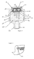
- FIGS 1 and 2 show a housing 10 for a flammable gas detector.
- the housing consists of two parts 11 and 12 which screw together to form an enclosed chamber 13.
- a porous sinter element 14 of the type provided with a support ring 15 is mounted at one end of the housing and provides the means by which the interior of the housing communicates with the outside.
- the housing 10 accommodates the sensing elements of the flammable gas detector.
- a sensor retainer 16 in the form of a flanged circular disc with two axially-extending holes 17 locates a sensing element 18 and a reference element or control 19 within the housing.
- the elements 18 and 19 are of similar construction.
- the embodiment shown in the drawings has a single sensing element and a single reference element, other arrangements are possible.
- the sensor retainer may locate multiple beads connected in series for the sensing element and the reference element.
- the sensing element 18 consists a heater wire 20 connected between two lead-in conductors 21 which are mounted in a supporting block 22.
- a bead 23 of catalyst material distributed over a porous substrate is formed around the heater wire.
- the reference element is identical to the sensing element except that the bead is inert, either because the catalyst material is omitted or because the catalyst has been deliberately poisoned.
- the lead-in conductors of the elements are connected to the outside by leads (not shown) which pass through a sleeve portion 24 of reduced diameter at the opposite end of the housing to the sinter element 14.
- the housing of the assembled detector is filled with an encapsulant 25 such as epoxy resin.
- the sensing element and the reference element are connected into opposite arms of a Wheatstone Bridge circuit (not shown).
- An electric current is passed through the heater wires 20 of the elements 18 and 19 and heats the beads 23.
- the resistances of the two elements 18 and 19 are the same and the arms of the Wheatstone bridge are balanced resulting in no voltage drop across the arms.
- the first part 11 of the housing 10 is made by moulding plastics material around the support ring 15, which supports the sinter element 14.
- One part of a die, the female die has a raised circular core.
- the sinter element is centred over the raised circular core such that the entire periphery of the support ring 15 overhangs the raised core.
- the male die has a smaller cross-sectional area, fitting inside the female die and locating onto and around the sinter element such that the sinter element 14 is entirely enclosed between the male die and the core of the female die keeping the plastics material from coming into contact with the sinter element.
- Hot plastics material is injected into the die mould, and allowed to set.
- the plastics material which now incorporates the sinter element is turned out of the mould to form the first part 10 of the housing as shown in Figures 2 and 3.
- the moulded interface 26 between the plastics first part 11 of the housing 10 and the support ring 15 avoids the creation of any flame path between the housing and the support ring whilst retaining the properties of the sinter element, namely its gas permeability and its ability to quench a flame front.
- the first part of the housing manufactured in this way has one end formed with an aperture 27 which is closed by the sinter element 14, the other end 29 being open and having an external screw thread 30.
- the sensor retainer 16 fits inside the first part 11 of the housing, locating against the interior face of the sinter element 14 and a shoulder 28 formed on the inside of the housing.
- the sensor retainer holds the sensing and reference elements 18 and 19 in the required positions on the inside of the sinter element 14.
- the second part 12 of the housing 10 is also moulded of plastics material
- One end 31 of the part 12 has an internal screw thread 32 which matches the external screw thread 30 at the end 29 of the first part 11 and allows the two parts to be screwed together to form the enclosed chamber 13.
- the other end 33 of the second part of the housing is formed with an integral sleeve 24 of reduced diameter to allow electrical connection of the sensing and reference elements to the electrical circuitry of the Wheatstone Bridge (not shown).
- the housing is moulded from a plastics material which will provide satisfactory performance at the operation temperatures which the detector is likely to experience.
- Suitable thermoplastics include, but are not limited to, mineral filled polyphenylsulphide, polybutylterepthalate, and liquid crystal polymer such as poly(benzoate-napthoate).
- thermosetting plastics such as dough moulding compound-polyester may be used.
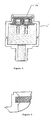
- Figures 4 and 5 show an alternative embodiment of the invention, in which the sinter element has no support ring and the first part 11' of the housing is moulded directly onto the sinter element 14' itself, so that the sinter element is in intimate contact with the first part of the plastics housing.
- the sinter element is manufactured with an increased density around its periphery which results in the centre portion of the sinter element remaining permeable to gases, and the peripheral portions of the sinter element being less susceptible to wicking of the hot plastics.
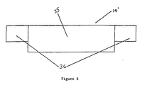
- FIG. 6 shows a sinter element 14' which has been manufactured to provide a gas permeable central portion 35 and denser peripheral portions 36.
- Sinter elements of this type may be manufactured in a variety of ways.
- Flame arrestors, in the form of sinter elements may be produced by pouring powdered metal of a known grain size into a mould which forms one half of a die set. The second half of the die set is lowered and pressure is applied to the powder allowing some of the particles to bond together in a brittle biscuit-like form known as a green-state sinter. This green sinter is then fired in a furnace, the firing normally being performed in a reducing atmosphere to ensure that the powder remains in the metallic state.
- the metal particles are fused together giving the structure great strength while at the same time providing many routes for gas to pass through the sinter element albeit over a distance far greater than the thickness of the sinter element.
- a flame front present in the interior of a detector housing may also commence along these paths.
- the combination of the high thermal conductivity of the metal particles and the length of the path through which the flame front must travel to reach the side of the sinter element in contact with the surrounding environment ensures that any flame front is quenched before it reaches the surrounding environment.
- the sinter element presents very little resistance to the passage of gases.
- One method for producing a sinter element with increased sinter density around its periphery is to produce a normal, flat green state sinter element which is then placed in a second die such that an increased pressure is applied only to the periphery of the sinter element only. The periphery therefore is compressed further and the powder particles become more densely packed. The sinter is then fired in the normal way, using a combination of reducing furnaces. By applying sufficient pressure to the periphery during the manufacturing process it can be made so dense in the finished product that wicking is reduced or even eliminated.
- the resultant sinter element has a gas permeable centre section 35 and a denser periphery 36 which is less susceptible to wicking and which may even be totally impervious to gas.
- the initial die set can be constructed so that the powder is poured evenly into the mould and the second half of the die set has a recessed centre portion.
- the periphery of the sinter has greater pressure applied than the centre portion.
- the sinter element produced has a gas permeable centre section 35 and denser peripheral sections 36 which are less susceptible to wicking.
- the sinter can be made of two powders, a coarse powder in the centre and a fine powder toward the edge. Uniform pressure is applied to form the sinter. By the nature of the smaller grain size of fine powder a more dense and impermeable sinter is made at the outside. By manufacturing a sinter element with a denser periphery, the need for a support ring is avoided, and sinter elements may be manufactured more cheaply.
- the sinter element may be constructed by placing a greater thickness of powdered metal particles at the periphery so that in the finished article the thickness of the element is uniform with the periphery having a greater density than the centre.
Landscapes
- Chemical & Material Sciences (AREA)
- Chemical Kinetics & Catalysis (AREA)
- Electrochemistry (AREA)
- Physics & Mathematics (AREA)
- Health & Medical Sciences (AREA)
- Life Sciences & Earth Sciences (AREA)
- Analytical Chemistry (AREA)
- Biochemistry (AREA)
- General Health & Medical Sciences (AREA)
- General Physics & Mathematics (AREA)
- Immunology (AREA)
- Pathology (AREA)
- Investigating Or Analyzing Materials By The Use Of Electric Means (AREA)
- Investigating Or Analyzing Materials By The Use Of Fluid Adsorption Or Reactions (AREA)
Description
- This invention relates to a housing for a flammable gas detector.
- One type of flammable gas detector employs a heated sensing element to oxidise any flammable gas present. Oxidation of flammable gases at the sensing element causes a change in electronic properties of the sensor which is detected to indicate the presence of a flammable gas. For example, a catalytic bead sensing element may comprise a coil of wire embedded in a porous bead containing a catalyst. The bead is heated electrically by passing current through the wire. If flammable gas is present at the bead, it oxidises exothermally in the presence of the catalyst, causing the temperature of the bead, and hence the wire coil, to increase. The change in resistance resulting from the change in temperature is detected to indicate the presence of a flammable gas. Frequently two bead elements are used in a Wheatstone bridge arrangement with one element acting as the sensor and the other being of similar construction but rendered inert and acting as a control. Higher output, and hence greater sensitivity, can be obtained by using multiple beads connected in series or through the use of electronic amplification of the output signal.
- Although, for operation of the detector, the gas within the detector housing must communicate with the surrounding ambient gases, for reasons of safety, the gas undergoing oxidation within the housing must be prevented from igniting any flammable gas outside the housing. For this purpose, known detectors include in the wall of the housing a flame arrestor in the form of a sinter element, through which the interior of the housing communicates with the outside. The flame arrestor should provide as small a resistance to diffusion as is consistent with its primary requirements of strength and quenching the flame front.
- The housing for the sensor must be flameproof and capable of withstanding internal explosion without allowing a flame front to propagate outside the housing. Any joint or gaps in the housing must be small enough to attenuate the flame front such that it is incapable of igniting the gas outside the housing.
- Known housings are cast from metal. All potential flame paths require 100% inspection in order for the housing to meet the relevant safety standards. Not only must the flame arrestor element be itself designed to meet the required safety standards but it must be secured to the housing in such a way as to prevent a flame path being provided at the flame arrestor element/housing interface. In order to form a satisfactory flame arresting arrangement, the housing and sinter element must be in intimate contact along the entire length of the sinter element/housing interface. The periphery of the sinter element, and the internal surface of the housing over the region of contact with the sinter element, must be precisely formed. In practice to meet the tight tolerances required for satisfactory performance, the cast metal housing has to be precision machined.
- In manufacturing the known flammable gas detectors, the sinter element is fixed to the housing in a separate operation. The sinter element may be glued to the housing, or the housing may be peened over the sinter element, or the sinter element may be retained in the housing by peening the housing over the edges of the sinter element, and the sinter element subsequently glued in position.
- The precision machining, quality assurance and fixing operations required to ensure that the known housings meets safety standards, makes them time-consuming and expensive to manufacture.
- US-A-4,352,099 discloses a flammable gas detector having a sensing element, a cover made of sintered metal that encloses the sensing element and a washer to keep the sintered cover in place.
- WO-A-8404967 discloses a readily demountable gas detecting system having a housing made of plastics material and a removable gas sensor that is separated from the atmosphere being detected by a flame arresting filter, which is clamped in place by a top part of the housing.
- JP-A-58146845 describes a combustible gas sensor that is attached to a window hole in a polyimide film with an adhesive and is covered by an explosion-preventive mesh.
- According to the present invention there is provided a housing for a flammable gas detector comprising a housing body with an aperture through which the interior of the housing body communicates with the outside, a gas permeable flame arrestor element located in the aperture, at least a portion of the housing body surrounding the aperture being moulded from plastics materials, the portions of the housing body that form the aperture being moulded around the flame arrestor element with the flame arrestor element in situ whereby the flame arrestor element is fixed to the housing body. Moulding the body of the plastics housing around the flame arrestor element with the flame arrestor element in situ eliminates the operation of fixing the flame arrestor element into the housing. Moulding the plastics material directly onto the periphery of the flame arrestor element eliminates the flame path at the interface between the arrestor element and the housing. The requirements for machining the housing, and fixing the sinter element to the housing in a separate operation are eliminated reducing the overall number of manufacturing operations with subsequent savings in both manufacturing time and cost.
- A suitable plastics material is used for the housing body. It should exhibit high impact strength, mechanical rigidity, UV stability and flame retardant properties over an extensive temperature range. Suitable plastics might be thermoplastic, for example mineral-filled PPS (polyphenylsulphide), PBT (polybutylterepthalate), or LCP (liquid crystal polymer such as poly(benzoate-napthoate)). Alternatively, thermosetting plastics such as DMC (dough-moulding compound -polyester) might be used.
- The porous nature of sinter elements allows any hot plastics which comes into contact with the sinter element to be wicked into the sinter element, reducing the gas permeability of the sinter element and, therefore, its effectiveness. When a sinter element which has a support ring around its periphery is used, the housing can be designed so that the hot plastics comes into contact only with the support ring and never into direct contact with the porous sinter element.
- If the housing is to be moulded around a sinter element which does not have a support ring, wicking may be reduced, or eliminated, by using a sinter element which has a greater density around its periphery where the housing and the sinter element will be joined, than in the middle. By making the periphery denser, the pore size is reduced and the molten plastics material cannot penetrate the sinter material so easily where it comes into contact with the housing.
- Preferred embodiments of the invention will now be described in more detail with reference to the drawings in which:-
- Figure 1 is a side elevation of the housing;
- Figure 2 is a section through the housing of Figure 1 along the line A-A showing a sinter element with a support ring;
- Figure 3 is an enlarged section of the sinter element/housing junction of Figure 2;
- Figure 4 is a section of the housing of Figure 1 along the line A-A showing a sinter element without a support ring;
- Figure 5 is an enlarged section of the sinter element/housing junction of Figure 4; and
- Figure 6 shows a sinter element which has increased density around its periphery.
- Figures 1 and 2 show a
housing 10 for a flammable gas detector. The housing consists of twoparts 11 and 12 which screw together to form an enclosedchamber 13. Aporous sinter element 14 of the type provided with asupport ring 15 is mounted at one end of the housing and provides the means by which the interior of the housing communicates with the outside. - The
housing 10 accommodates the sensing elements of the flammable gas detector. Asensor retainer 16 in the form of a flanged circular disc with two axially-extending holes 17 locates asensing element 18 and a reference element orcontrol 19 within the housing. Theelements - The
sensing element 18 consists aheater wire 20 connected between two lead-in conductors 21 which are mounted in a supportingblock 22. Abead 23 of catalyst material distributed over a porous substrate is formed around the heater wire. - The reference element is identical to the sensing element except that the bead is inert, either because the catalyst material is omitted or because the catalyst has been deliberately poisoned.
- The lead-in conductors of the elements are connected to the outside by leads (not shown) which pass through a
sleeve portion 24 of reduced diameter at the opposite end of the housing to thesinter element 14. The housing of the assembled detector is filled with an encapsulant 25 such as epoxy resin. - The sensing element and the reference element are connected into opposite arms of a Wheatstone Bridge circuit (not shown). An electric current is passed through the
heater wires 20 of theelements beads 23. In the absence of flammable gases, the resistances of the twoelements - If there is a flammable gas present in the ambient atmosphere around the
housing 10, some will diffuse through thesinter element 14 into the holes 17 in which the sensing andreference elements sensing element 18 causes any flammable gases around it to oxidise in an exothermic reaction. This reaction heats the bead of thesensing element 18 and causes the temperature of its heating wire to increase, which, in turn, causes the resistance of the wire to increase. The increase in resistance of thesensing element 18 compared with the resistance of thereference element 19 causes the Wheatstone Bridge to become unbalanced and a voltage drop across the bridge is detected to indicate the presence of the flammable gas. - The construction of the housing will now be described in more detail. The
first part 11 of thehousing 10 is made by moulding plastics material around thesupport ring 15, which supports thesinter element 14. One part of a die, the female die, has a raised circular core. The sinter element is centred over the raised circular core such that the entire periphery of thesupport ring 15 overhangs the raised core. The male die has a smaller cross-sectional area, fitting inside the female die and locating onto and around the sinter element such that thesinter element 14 is entirely enclosed between the male die and the core of the female die keeping the plastics material from coming into contact with the sinter element. Hot plastics material is injected into the die mould, and allowed to set. - The plastics material which now incorporates the sinter element is turned out of the mould to form the
first part 10 of the housing as shown in Figures 2 and 3. The mouldedinterface 26 between the plasticsfirst part 11 of thehousing 10 and thesupport ring 15 avoids the creation of any flame path between the housing and the support ring whilst retaining the properties of the sinter element, namely its gas permeability and its ability to quench a flame front. The first part of the housing manufactured in this way has one end formed with an aperture 27 which is closed by thesinter element 14, theother end 29 being open and having anexternal screw thread 30. - The
sensor retainer 16 fits inside thefirst part 11 of the housing, locating against the interior face of thesinter element 14 and ashoulder 28 formed on the inside of the housing. The sensor retainer holds the sensing andreference elements sinter element 14. - The second part 12 of the
housing 10 is also moulded of plastics material Oneend 31 of the part 12 has aninternal screw thread 32 which matches theexternal screw thread 30 at theend 29 of thefirst part 11 and allows the two parts to be screwed together to form theenclosed chamber 13. - The
other end 33 of the second part of the housing is formed with anintegral sleeve 24 of reduced diameter to allow electrical connection of the sensing and reference elements to the electrical circuitry of the Wheatstone Bridge (not shown). With thesensor retainer 16 holding theelements parts 11 and 12 are screwed together. The end of thechamber 13 between theretainer 16 and thesleeve 24 is then filled with anepoxy resin encapsulant 25, sealing the interior of the housing, apart from the holes 17 which accommodate theelements - The housing is moulded from a plastics material which will provide satisfactory performance at the operation temperatures which the detector is likely to experience. Suitable thermoplastics include, but are not limited to, mineral filled polyphenylsulphide, polybutylterepthalate, and liquid crystal polymer such as poly(benzoate-napthoate). Alternatively thermosetting plastics such as dough moulding compound-polyester may be used.
- Figures 4 and 5 show an alternative embodiment of the invention, in which the sinter element has no support ring and the first part 11' of the housing is moulded directly onto the sinter element 14' itself, so that the sinter element is in intimate contact with the first part of the plastics housing. In order to prevent hot plastics of the housing from wicking into the sinter element 14' during the injection moulding process, the sinter element is manufactured with an increased density around its periphery which results in the centre portion of the sinter element remaining permeable to gases, and the peripheral portions of the sinter element being less susceptible to wicking of the hot plastics.
- Figure 6 shows a sinter element 14' which has been manufactured to provide a gas permeable
central portion 35 and denser peripheral portions 36. Sinter elements of this type may be manufactured in a variety of ways. Flame arrestors, in the form of sinter elements, may be produced by pouring powdered metal of a known grain size into a mould which forms one half of a die set. The second half of the die set is lowered and pressure is applied to the powder allowing some of the particles to bond together in a brittle biscuit-like form known as a green-state sinter. This green sinter is then fired in a furnace, the firing normally being performed in a reducing atmosphere to ensure that the powder remains in the metallic state. In the final sintered structure the metal particles are fused together giving the structure great strength while at the same time providing many routes for gas to pass through the sinter element albeit over a distance far greater than the thickness of the sinter element. A flame front present in the interior of a detector housing may also commence along these paths. However, the combination of the high thermal conductivity of the metal particles and the length of the path through which the flame front must travel to reach the side of the sinter element in contact with the surrounding environment ensures that any flame front is quenched before it reaches the surrounding environment. The sinter element presents very little resistance to the passage of gases. - One method for producing a sinter element with increased sinter density around its periphery is to produce a normal, flat green state sinter element which is then placed in a second die such that an increased pressure is applied only to the periphery of the sinter element only. The periphery therefore is compressed further and the powder particles become more densely packed. The sinter is then fired in the normal way, using a combination of reducing furnaces. By applying sufficient pressure to the periphery during the manufacturing process it can be made so dense in the finished product that wicking is reduced or even eliminated. The resultant sinter element has a gas
permeable centre section 35 and a denser periphery 36 which is less susceptible to wicking and which may even be totally impervious to gas. - In another method the initial die set can be constructed so that the powder is poured evenly into the mould and the second half of the die set has a recessed centre portion. When pressure is applied to the second half of the die, the periphery of the sinter has greater pressure applied than the centre portion. When fired as above, the sinter element produced has a gas
permeable centre section 35 and denser peripheral sections 36 which are less susceptible to wicking. - In a third method the sinter can be made of two powders, a coarse powder in the centre and a fine powder toward the edge. Uniform pressure is applied to form the sinter. By the nature of the smaller grain size of fine powder a more dense and impermeable sinter is made at the outside. By manufacturing a sinter element with a denser periphery, the need for a support ring is avoided, and sinter elements may be manufactured more cheaply.
- In alternative embodiments, the sinter element may be constructed by placing a greater thickness of powdered metal particles at the periphery so that in the finished article the thickness of the element is uniform with the periphery having a greater density than the centre.
Claims (13)
- A housing for a flammable gas detector comprising a housing body with an aperture through which the interior of the housing body communicates with the outside, a gas permeable flame arrestor element located in the aperture, at least a portion of the housing body surrounding the aperture being moulded from the plastics material, the portions of the housing body that form the aperture being moulded around the flame arrestor element with the flame arrestor element in situ whereby the flame arrestor element is fixed to the housing body.
- A housing for a flammable gas detector according to claim 1, wherein the flame arrestor element is provided by a sinter element.
- A housing for a flammable gas detector according to claim 2, wherein the flame arrestor element includes a support ring, the support ring being disposed around the sinter element and the plastics material of the housing body being moulded onto the support ring.
- A housing for a flammable gas detector according to claim 2, wherein the density of the sinter element is greater around the periphery of the sinter element than in the centre.
- A housing for a flammable gas detector according to claim 4, wherein the sinter element is provided with an increased density of sinter around its periphery by use of a fine grain powder around the periphery and a coarser grained powder in the centre.
- A housing for a flammable gas detector according to any of the preceding claims wherein the material of the housing is thermoplastic and is mineral filled polyphenylsulphide, polybutylterephthalate or poly(benzoate-naphthoate).
- A housing for a flammable gas detector according to any one of claims 1 to 5, wherein the plastics material of the housing is thermosetting and is a dough moulding compound-polyester.
- A method of forming a housing for a flammable gas detector according to claim 1 comprising moulding at least a portion of a housing body from plastics around the periphery of a gas permeable flame arrestor element.
- A method of forming a housing for a flammable gas detector according to claim 8, wherein the flame arrestor element includes a sinter element.
- A method according to claim 9 including forming the sinter element from powdered metal, the periphery of the sinter element being compressed to form a material of greater density than at the centre.
- A method according to claim 10, wherein the sinter element is provided with increased density of sinter around its periphery by a second pressing of an unfired, green-state sinter.
- A method according to claim 10, wherein the sinter element is provided with an increased density around its periphery in a single moulding operation using a stepped or graduated mould.
- A method according to any of claims 8 to 12, wherein the plastics housing is manufactured by injection moulding the plastics material around the flame arrestor element.
Applications Claiming Priority (3)
| Application Number | Priority Date | Filing Date | Title |
|---|---|---|---|
| GB9717462 | 1997-08-18 | ||
| GB9717462A GB2328508B (en) | 1997-08-18 | 1997-08-18 | Housing for a flammable gas detector |
| PCT/GB1998/002469 WO1999009409A1 (en) | 1997-08-18 | 1998-08-18 | Housing for a flammable gas detector |
Publications (2)
| Publication Number | Publication Date |
|---|---|
| EP1005646A1 EP1005646A1 (en) | 2000-06-07 |
| EP1005646B1 true EP1005646B1 (en) | 2006-09-27 |
Family
ID=10817643
Family Applications (1)
| Application Number | Title | Priority Date | Filing Date |
|---|---|---|---|
| EP98939739A Expired - Lifetime EP1005646B1 (en) | 1997-08-18 | 1998-08-18 | Housing for a flammable gas detector |
Country Status (6)
| Country | Link |
|---|---|
| US (1) | US6351982B1 (en) |
| EP (1) | EP1005646B1 (en) |
| DE (1) | DE69836027T2 (en) |
| ES (1) | ES2274575T3 (en) |
| GB (1) | GB2328508B (en) |
| WO (1) | WO1999009409A1 (en) |
Families Citing this family (12)
| Publication number | Priority date | Publication date | Assignee | Title |
|---|---|---|---|---|
| US6754067B2 (en) * | 2002-09-06 | 2004-06-22 | Mine Safety Appliances Company | Instrument assembly systems, housing and methods of mounting instrument assemblies |
| WO2004048955A2 (en) * | 2002-11-27 | 2004-06-10 | City Technology Limited | Gas sensing device |
| AU2003286267A1 (en) * | 2002-11-27 | 2004-06-18 | City Technology Limited | Gas sensing assembly |
| GB0227686D0 (en) * | 2002-11-27 | 2003-01-08 | City Tech | Gas sensing device |
| TWI239916B (en) * | 2005-01-18 | 2005-09-21 | Lite On Automotive Corp | Security apparatus for motor vehicles |
| US9410911B2 (en) * | 2013-04-23 | 2016-08-09 | Hewlett-Packard Development Company, L.P. | Structure and method of manufacture |
| DE102013109259A1 (en) * | 2013-08-27 | 2015-03-05 | R.Stahl Schaltgeräte GmbH | Pressure relief device for an explosion-proof housing and method for its manufacture |
| TWM536542U (en) * | 2016-07-27 | 2017-02-11 | 林信湧 | Health gas production system |
| US12618818B2 (en) | 2020-09-02 | 2026-05-05 | Nevada Nanotech Systems Inc. | Arrays of gas sensor device packages, and related methods |
| CN216594992U (en) * | 2020-10-14 | 2022-05-24 | 现代凯菲克株式会社 | Gas sensor |
| CN112191047A (en) * | 2020-10-19 | 2021-01-08 | 重庆电子工程职业学院 | Filtering device of electrochemical carbon monoxide sensor |
| CN113263461B (en) * | 2021-05-18 | 2022-10-28 | 山东信力工矿安全检测有限公司 | Lightning arrester detection device |
Family Cites Families (14)
| Publication number | Priority date | Publication date | Assignee | Title |
|---|---|---|---|---|
| CH638636A5 (en) * | 1979-03-16 | 1983-09-30 | Cerberus Ag | GAS DETECTOR FOR USE IN AN EXPLOSION HAZARDOUS ENVIRONMENT. |
| US4263588A (en) * | 1979-07-25 | 1981-04-21 | Oldham France S.A. | Helmet-carried apparatus for detecting and signalling the presence of a dangerous gas in an atmosphere |
| US4317868A (en) * | 1980-09-19 | 1982-03-02 | Gould Inc. | Battery vent plug with flame arrestor |
| JPS58146845A (en) * | 1982-02-24 | 1983-09-01 | Ricoh Co Ltd | Gas sensor |
| DK265183A (en) * | 1983-06-10 | 1984-12-11 | Haraldsted Hans Henrik | GAS SENSOR EVENT |
| JPS6080749A (en) * | 1983-10-08 | 1985-05-08 | Shinkosumosu Denki Kk | Manufacturing method of flame arrester for gas sensor |
| GB8928177D0 (en) * | 1989-12-13 | 1990-02-14 | City Tech | Flammable gas detection |
| JPH0599871A (en) * | 1991-06-20 | 1993-04-23 | Yamatake Honeywell Co Ltd | Component detector for explosion-proof |
| US5215835A (en) * | 1991-09-11 | 1993-06-01 | Globe-Union Inc. | Metal oxide-hydrogen battery having an outer safety shell |
| US5331310A (en) * | 1992-04-06 | 1994-07-19 | Transducer Research, Inc. | Amperometric carbon monoxide sensor module for residential alarms |
| US5481904A (en) * | 1994-09-28 | 1996-01-09 | The United States Of America As Represented By The Secretary Of The Navy | Oil spillage detector |
| US5495747A (en) * | 1994-09-30 | 1996-03-05 | Mine Safety Appliances Company | Device for detecting gases for use in diffusion and forced flow modes |
| US5709187A (en) * | 1996-04-30 | 1998-01-20 | Brunswick Corporation | Flame arrestor |
| GB2339474B (en) * | 1998-07-10 | 2000-07-05 | Draeger Sicherheitstech Gmbh | A flashback barrier |
-
1997
- 1997-08-18 GB GB9717462A patent/GB2328508B/en not_active Expired - Fee Related
-
1998
- 1998-08-18 EP EP98939739A patent/EP1005646B1/en not_active Expired - Lifetime
- 1998-08-18 US US09/485,756 patent/US6351982B1/en not_active Expired - Lifetime
- 1998-08-18 WO PCT/GB1998/002469 patent/WO1999009409A1/en not_active Ceased
- 1998-08-18 DE DE69836027T patent/DE69836027T2/en not_active Expired - Lifetime
- 1998-08-18 ES ES98939739T patent/ES2274575T3/en not_active Expired - Lifetime
Also Published As
| Publication number | Publication date |
|---|---|
| GB9717462D0 (en) | 1997-10-22 |
| DE69836027D1 (en) | 2006-11-09 |
| DE69836027T2 (en) | 2007-04-19 |
| EP1005646A1 (en) | 2000-06-07 |
| ES2274575T3 (en) | 2007-05-16 |
| US6351982B1 (en) | 2002-03-05 |
| WO1999009409A1 (en) | 1999-02-25 |
| GB2328508B (en) | 2002-02-13 |
| GB2328508A (en) | 1999-02-24 |
Similar Documents
| Publication | Publication Date | Title |
|---|---|---|
| US6351982B1 (en) | Housing for a flammable gas detector | |
| CA1136702A (en) | Flat electrochemical sensor, and method of its manufacture | |
| CA1319837C (en) | Integrated heatable sensor | |
| US4151503A (en) | Temperature compensated resistive exhaust gas sensor construction | |
| EP0313390A2 (en) | Gas sensor and method for production thereof | |
| EP1167961B9 (en) | Gas sensor and manufacturing method for the same | |
| GB2075690A (en) | Solid electrolyte electrochemical measuring sensor for determining the oxygen content of gases | |
| US5351539A (en) | Sensor for measuring acceleration and tilt with a bubble level | |
| CN101666775B (en) | Gas sensor and gas sensor unit | |
| JPH1194668A (en) | Combination type fluid pressure and temperature sensor device | |
| US3911386A (en) | Exhaust gas air fuel ratio sensor | |
| JPH02115758A (en) | Relative-concentration measuring device for fluid reaction substance | |
| USRE32571E (en) | Method of manufacturing corrosion-resistant measuring probes | |
| US4935289A (en) | Gas sensor and method for production thereof | |
| JP2683012B2 (en) | Thermal conductivity detector and its cell, and method of manufacturing cell | |
| EP0018283B1 (en) | Pressure sensor | |
| EP1565734B1 (en) | Gas sensing device | |
| US4340409A (en) | Method of fabricating a pressure sensor | |
| US3809639A (en) | Solid electrolyte compact for probe used in quantitative determination of gas dissolved in molten metal | |
| US3835529A (en) | Gas detecting device and method of making same | |
| KR20050076639A (en) | Oxygen concentration detecting element and method of producing the same | |
| US5061350A (en) | Method for producing detecting element | |
| US4426406A (en) | Method of fabricating a pressure sensor | |
| JPH0251138B2 (en) | ||
| EP3346267B1 (en) | Sensor device for detecting a permanent gas |
Legal Events
| Date | Code | Title | Description |
|---|---|---|---|
| PUAI | Public reference made under article 153(3) epc to a published international application that has entered the european phase |
Free format text: ORIGINAL CODE: 0009012 |
|
| 17P | Request for examination filed |
Effective date: 20000320 |
|
| AK | Designated contracting states |
Kind code of ref document: A1 Designated state(s): BE CH DE DK ES FI FR GB IE IT LI NL PT SE |
|
| 17Q | First examination report despatched |
Effective date: 20040524 |
|
| GRAP | Despatch of communication of intention to grant a patent |
Free format text: ORIGINAL CODE: EPIDOSNIGR1 |
|
| GRAS | Grant fee paid |
Free format text: ORIGINAL CODE: EPIDOSNIGR3 |
|
| GRAA | (expected) grant |
Free format text: ORIGINAL CODE: 0009210 |
|
| AK | Designated contracting states |
Kind code of ref document: B1 Designated state(s): BE CH DE DK ES FI FR GB IE IT LI NL PT SE |
|
| PG25 | Lapsed in a contracting state [announced via postgrant information from national office to epo] |
Ref country code: NL Free format text: LAPSE BECAUSE OF FAILURE TO SUBMIT A TRANSLATION OF THE DESCRIPTION OR TO PAY THE FEE WITHIN THE PRESCRIBED TIME-LIMIT Effective date: 20060927 Ref country code: LI Free format text: LAPSE BECAUSE OF FAILURE TO SUBMIT A TRANSLATION OF THE DESCRIPTION OR TO PAY THE FEE WITHIN THE PRESCRIBED TIME-LIMIT Effective date: 20060927 Ref country code: IT Free format text: LAPSE BECAUSE OF FAILURE TO SUBMIT A TRANSLATION OF THE DESCRIPTION OR TO PAY THE FEE WITHIN THE PRE;WARNING: LAPSES OF ITALIAN PATENTS WITH EFFECTIVE DATE BEFORE 2007 MAY HAVE OCCURRED AT ANY TIME BEFORE 2007. THE CORRECT EFFECTIVE DATE MAY BE DIFFERENT FROM THE ONE RECORDED.SCRIBED TIME-LIMIT Effective date: 20060927 Ref country code: FI Free format text: LAPSE BECAUSE OF FAILURE TO SUBMIT A TRANSLATION OF THE DESCRIPTION OR TO PAY THE FEE WITHIN THE PRESCRIBED TIME-LIMIT Effective date: 20060927 Ref country code: CH Free format text: LAPSE BECAUSE OF FAILURE TO SUBMIT A TRANSLATION OF THE DESCRIPTION OR TO PAY THE FEE WITHIN THE PRESCRIBED TIME-LIMIT Effective date: 20060927 Ref country code: BE Free format text: LAPSE BECAUSE OF FAILURE TO SUBMIT A TRANSLATION OF THE DESCRIPTION OR TO PAY THE FEE WITHIN THE PRESCRIBED TIME-LIMIT Effective date: 20060927 |
|
| REG | Reference to a national code |
Ref country code: GB Ref legal event code: FG4D |
|
| REG | Reference to a national code |
Ref country code: CH Ref legal event code: EP |
|
| REG | Reference to a national code |
Ref country code: IE Ref legal event code: FG4D |
|
| REF | Corresponds to: |
Ref document number: 69836027 Country of ref document: DE Date of ref document: 20061109 Kind code of ref document: P |
|
| RAP2 | Party data changed (patent owner data changed or rights of a patent transferred) |
Owner name: HONEYWELL ANALYTICS LIMITED |
|
| PG25 | Lapsed in a contracting state [announced via postgrant information from national office to epo] |
Ref country code: SE Free format text: LAPSE BECAUSE OF FAILURE TO SUBMIT A TRANSLATION OF THE DESCRIPTION OR TO PAY THE FEE WITHIN THE PRESCRIBED TIME-LIMIT Effective date: 20061227 Ref country code: DK Free format text: LAPSE BECAUSE OF FAILURE TO SUBMIT A TRANSLATION OF THE DESCRIPTION OR TO PAY THE FEE WITHIN THE PRESCRIBED TIME-LIMIT Effective date: 20061227 |
|
| NLT2 | Nl: modifications (of names), taken from the european patent patent bulletin |
Owner name: HONEYWELL ANALYTICS LIMITED Effective date: 20061115 |
|
| NLV1 | Nl: lapsed or annulled due to failure to fulfill the requirements of art. 29p and 29m of the patents act | ||
| PG25 | Lapsed in a contracting state [announced via postgrant information from national office to epo] |
Ref country code: PT Free format text: LAPSE BECAUSE OF FAILURE TO SUBMIT A TRANSLATION OF THE DESCRIPTION OR TO PAY THE FEE WITHIN THE PRESCRIBED TIME-LIMIT Effective date: 20070313 |
|
| REG | Reference to a national code |
Ref country code: CH Ref legal event code: PL |
|
| ET | Fr: translation filed | ||
| REG | Reference to a national code |
Ref country code: ES Ref legal event code: FG2A Ref document number: 2274575 Country of ref document: ES Kind code of ref document: T3 |
|
| PLBE | No opposition filed within time limit |
Free format text: ORIGINAL CODE: 0009261 |
|
| STAA | Information on the status of an ep patent application or granted ep patent |
Free format text: STATUS: NO OPPOSITION FILED WITHIN TIME LIMIT |
|
| 26N | No opposition filed |
Effective date: 20070628 |
|
| PG25 | Lapsed in a contracting state [announced via postgrant information from national office to epo] |
Ref country code: IE Free format text: LAPSE BECAUSE OF NON-PAYMENT OF DUE FEES Effective date: 20070820 |
|
| PGFP | Annual fee paid to national office [announced via postgrant information from national office to epo] |
Ref country code: ES Payment date: 20080821 Year of fee payment: 11 |
|
| PGFP | Annual fee paid to national office [announced via postgrant information from national office to epo] |
Ref country code: IT Payment date: 20080816 Year of fee payment: 11 Ref country code: FR Payment date: 20080807 Year of fee payment: 11 |
|
| REG | Reference to a national code |
Ref country code: FR Ref legal event code: ST Effective date: 20100430 |
|
| PG25 | Lapsed in a contracting state [announced via postgrant information from national office to epo] |
Ref country code: FR Free format text: LAPSE BECAUSE OF NON-PAYMENT OF DUE FEES Effective date: 20090831 |
|
| REG | Reference to a national code |
Ref country code: ES Ref legal event code: FD2A Effective date: 20090819 |
|
| PG25 | Lapsed in a contracting state [announced via postgrant information from national office to epo] |
Ref country code: IT Free format text: LAPSE BECAUSE OF NON-PAYMENT OF DUE FEES Effective date: 20090818 |
|
| PG25 | Lapsed in a contracting state [announced via postgrant information from national office to epo] |
Ref country code: ES Free format text: LAPSE BECAUSE OF NON-PAYMENT OF DUE FEES Effective date: 20090819 |
|
| PGFP | Annual fee paid to national office [announced via postgrant information from national office to epo] |
Ref country code: GB Payment date: 20120726 Year of fee payment: 15 |
|
| PGFP | Annual fee paid to national office [announced via postgrant information from national office to epo] |
Ref country code: DE Payment date: 20120831 Year of fee payment: 15 |
|
| GBPC | Gb: european patent ceased through non-payment of renewal fee |
Effective date: 20130818 |
|
| PG25 | Lapsed in a contracting state [announced via postgrant information from national office to epo] |
Ref country code: DE Free format text: LAPSE BECAUSE OF NON-PAYMENT OF DUE FEES Effective date: 20140301 |
|
| REG | Reference to a national code |
Ref country code: DE Ref legal event code: R119 Ref document number: 69836027 Country of ref document: DE Effective date: 20140301 |
|
| PG25 | Lapsed in a contracting state [announced via postgrant information from national office to epo] |
Ref country code: GB Free format text: LAPSE BECAUSE OF NON-PAYMENT OF DUE FEES Effective date: 20130818 |