EP1005257A2 - Computed tomography - Google Patents
Computed tomography Download PDFInfo
- Publication number
- EP1005257A2 EP1005257A2 EP99308855A EP99308855A EP1005257A2 EP 1005257 A2 EP1005257 A2 EP 1005257A2 EP 99308855 A EP99308855 A EP 99308855A EP 99308855 A EP99308855 A EP 99308855A EP 1005257 A2 EP1005257 A2 EP 1005257A2
- Authority
- EP
- European Patent Office
- Prior art keywords
- beams
- ray
- examination region
- fan
- radiation
- Prior art date
- Legal status (The legal status is an assumption and is not a legal conclusion. Google has not performed a legal analysis and makes no representation as to the accuracy of the status listed.)
- Withdrawn
Links
- 238000002591 computed tomography Methods 0.000 title description 11
- 230000005855 radiation Effects 0.000 claims abstract description 38
- 238000000034 method Methods 0.000 claims description 12
- 238000002059 diagnostic imaging Methods 0.000 claims description 4
- 230000000149 penetrating effect Effects 0.000 claims description 3
- 238000003384 imaging method Methods 0.000 description 9
- 238000003491 array Methods 0.000 description 3
- 230000000712 assembly Effects 0.000 description 3
- 238000000429 assembly Methods 0.000 description 3
- 230000002238 attenuated effect Effects 0.000 description 1
- 238000013170 computed tomography imaging Methods 0.000 description 1
- 238000013480 data collection Methods 0.000 description 1
- 238000010586 diagram Methods 0.000 description 1
- 230000006870 function Effects 0.000 description 1
- 230000000977 initiatory effect Effects 0.000 description 1
- 230000001678 irradiating effect Effects 0.000 description 1
- 238000009877 rendering Methods 0.000 description 1
- 238000000926 separation method Methods 0.000 description 1
Images


Classifications
-
- A—HUMAN NECESSITIES
- A61—MEDICAL OR VETERINARY SCIENCE; HYGIENE
- A61B—DIAGNOSIS; SURGERY; IDENTIFICATION
- A61B6/00—Apparatus for radiation diagnosis, e.g. combined with radiation therapy equipment
- A61B6/02—Devices for diagnosis sequentially in different planes; Stereoscopic radiation diagnosis
- A61B6/03—Computerised tomographs
- A61B6/032—Transmission computed tomography [CT]
-
- A—HUMAN NECESSITIES
- A61—MEDICAL OR VETERINARY SCIENCE; HYGIENE
- A61B—DIAGNOSIS; SURGERY; IDENTIFICATION
- A61B6/00—Apparatus for radiation diagnosis, e.g. combined with radiation therapy equipment
- A61B6/40—Apparatus for radiation diagnosis, e.g. combined with radiation therapy equipment with arrangements for generating radiation specially adapted for radiation diagnosis
- A61B6/4007—Apparatus for radiation diagnosis, e.g. combined with radiation therapy equipment with arrangements for generating radiation specially adapted for radiation diagnosis characterised by using a plurality of source units
- A61B6/4014—Apparatus for radiation diagnosis, e.g. combined with radiation therapy equipment with arrangements for generating radiation specially adapted for radiation diagnosis characterised by using a plurality of source units arranged in multiple source-detector units
-
- A—HUMAN NECESSITIES
- A61—MEDICAL OR VETERINARY SCIENCE; HYGIENE
- A61B—DIAGNOSIS; SURGERY; IDENTIFICATION
- A61B6/00—Apparatus for radiation diagnosis, e.g. combined with radiation therapy equipment
- A61B6/40—Apparatus for radiation diagnosis, e.g. combined with radiation therapy equipment with arrangements for generating radiation specially adapted for radiation diagnosis
- A61B6/4064—Apparatus for radiation diagnosis, e.g. combined with radiation therapy equipment with arrangements for generating radiation specially adapted for radiation diagnosis specially adapted for producing a particular type of beam
- A61B6/4085—Cone-beams
-
- H—ELECTRICITY
- H05—ELECTRIC TECHNIQUES NOT OTHERWISE PROVIDED FOR
- H05G—X-RAY TECHNIQUE
- H05G1/00—X-ray apparatus involving X-ray tubes; Circuits therefor
- H05G1/08—Electrical details
- H05G1/26—Measuring, controlling or protecting
- H05G1/30—Controlling
- H05G1/34—Anode current, heater current or heater voltage of X-ray tube
-
- A—HUMAN NECESSITIES
- A61—MEDICAL OR VETERINARY SCIENCE; HYGIENE
- A61B—DIAGNOSIS; SURGERY; IDENTIFICATION
- A61B6/00—Apparatus for radiation diagnosis, e.g. combined with radiation therapy equipment
- A61B6/02—Devices for diagnosis sequentially in different planes; Stereoscopic radiation diagnosis
- A61B6/027—Devices for diagnosis sequentially in different planes; Stereoscopic radiation diagnosis characterised by the use of a particular data acquisition trajectory, e.g. helical or spiral
-
- A—HUMAN NECESSITIES
- A61—MEDICAL OR VETERINARY SCIENCE; HYGIENE
- A61B—DIAGNOSIS; SURGERY; IDENTIFICATION
- A61B6/00—Apparatus for radiation diagnosis, e.g. combined with radiation therapy equipment
- A61B6/40—Apparatus for radiation diagnosis, e.g. combined with radiation therapy equipment with arrangements for generating radiation specially adapted for radiation diagnosis
- A61B6/4021—Apparatus for radiation diagnosis, e.g. combined with radiation therapy equipment with arrangements for generating radiation specially adapted for radiation diagnosis involving movement of the focal spot
Definitions
- the present invention relates to computed tomography (CT), especially for diagnostic imaging.
- CT computed tomography
- the invention finds particular application in conjunction with volume CT imaging for medical purposes and will be described with particular reference thereto. However, it is to be appreciated that the present invention will also find application in conjunction with industrial, security, and other types of volume imaging apparatus and techniques.
- a thin, fan shaped beam of radiation is projected from an x-ray source through a region of interest.
- the radiation source is rotated about the region of interest such that the same thin slice of the region of interest is irradiated from a multiplicity of directions spanning 360°.
- an arc of radiation detectors is mounted to the same gantry as the radiation source such that the two rotate together.
- the x-ray detectors are mounted stationarily in a ring 360° around the subject.
- a single slice image is typically generated. After a first slice image is generated, a subject support is indexed by a slice width generally on the order of a few millimetres, and another slice is generated. This slice image and index technique is repeated until slices spanning the volume of interest are generated.
- One drawback to this type of imaging is the relatively long time necessary to generate a large plurality of slices. Because the first and last slice are taken at a significantly different time, the volume image is distorted by a time evolution of the region of interest.
- the patient is generally moved continuously through the x-ray beam as the x-ray source rotates around the region of interest.
- the fan shaped beam of radiation and the region of interest move in a spiral pattern relative to each other.
- the continuous motion is faster than indexing between slices, but still relatively slow.
- some scanners collimate the beam of radiation into two slices.
- two sets of radiation detectors disposed end to end are commonly provided.
- the thickness of the irradiated slice and the spacing between slices are adjustable. Such adjustments are relatively straightforward for two beams of radiation.
- the requirement that each beam of radiation strike only a single set of radiation detectors renders collimation into more than two beams mechanically awkward.
- the two beams originate from a common focal point, they are divergent, not parallel to each other. The divergent rays complicate and introduce errors into reconstruction techniques in which data is reconstructed into parallel slices.
- as radiation from a single source is collimated into more beams, such beams become more widely divergent.
- cone beam image reconstruction is computationally intensive and slow.
- cone beam imaging has a fixed resolution, based on detector size.
- cone beam reconstructions tend to suffer from insufficiency of data problems, image artifacts, and other reconstruction errors.
- a CT scanner includes a stationary gantry portion defining an examination region.
- a rotating gantry portion selectively rotates about the examination region.
- a plurality of anode elements, associated with the rotating gantry portion for selective bombardment by an electron stream, generate a plurality of parallel x-ray beams.
- a plurality of x-ray detectors receive the x-ray beams which have passed through the examination region. The detectors generate signals indicative of the x-ray beams received and a reconstruction processor processes these generated signals into an image representation.
- a method of diagnostic imaging includes concurrently generating a plurality of thin fan beams of penetrating radiation.
- the plurality of thin fan beams are passed through an examination region while the fan beams are concurrently rotating around the examination region.
- Each of the fan beams is detected after passing through the examination region and are used to generate electronic signals indicative of an amount of radiation which has passed through the examination region.
- a CT scanner includes a floor mounted or stationary gantry A whose position remains fixed during data collection.
- a multiple fan beam generator B is rotatably mounted on a rotating gantry C .
- the stationary gantry A includes a cylinder 10 that defines a patient receiving region 12 .
- a plurality of rings of radiation detectors 14 1 , 14 2 ,...14 n are disposed concentrically around the patient receiving region 12 .
- the radiation detectors are mounted on the stationary gantry portion such that a corresponding arc segment of the detectors receives each fan beam of radiation from the radiation source B which has traversed a corresponding parallel path through the examination region 12 .
- a plurality of arc segments of radiation detectors can be mounted to the rotating gantry portion C each in alignment with one of the fan beams to rotate with the x-ray source.
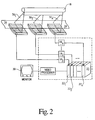
- a control console 16 contains an image reconstruction processor 18 for reconstructing a volumetric image representation using signals from the detector array 14 1 , 14 2 ,... 14 n for display on a monitor 20 .
- the reconstruction processor 18 includes a plurality of reconstruction processors 18 1 , 18 2 ,...18 n , each preprogrammed using conventional slice image reconstruction algorithms. This is illustrated in Figure 2 for the case in which the detectors are configured as a set of axially spaced arcs of detector elements (15) , but applies equally to the stationary detector rings 14 1 , 14 2 etc.
- the output from each of the detector rings 14 1 , 14 2 ,...14 n is fed to a corresponding processor 18 1 , 18 2 ,...18 n which reconstructs the data collected concurrently into a series of slices.
- the series of slices is then stored in a volume image memory 22 .
- the number of slices is less than the total number of slices in the volume and the slices are spread apart such that some fraction of the slices, e.g. every sixth slice, is generated concurrently. Thereafter, a patient couch 24 is stepped one slice distance and the next set of slices is generated concurrently. In the present example in which one sixth of the slices is taken each time, this process is repeated six times.
- the slices are again spaced by some short distance.
- the patient table 24 moves in either direction through the imaging area or back and forth continuously as the x-ray beams rotate continuously.
- the motion of the patient table is selected such that the data collected by each of the radiation detectors spirals in each of a plurality of contiguous slabs.
- the data in each of the slabs is reconstructed, preferably concurrently by a plurality of parallel processors, using conventional spiral volume imaging algorithms.
- the patient table moves back and forth a sufficient distance that the spirals overlap.
- the conventional spiral imaging algorithm is modified such that each of a series of preferably parallel processors is updating a corresponding region of volume image memory 22 , concurrently.
- the video monitor 20 converts selectable portions of the reconstructed volumetric image representation into a two-dimensional human-readable display.
- the console 16 also includes appropriate tape or disk recording devices, performing image enhancements, selecting planes for viewing, 3-D renderings, or colour enhancements or the like.
- image enhancements selecting planes for viewing, 3-D renderings, or colour enhancements or the like.
- scanner control functions such as initiating a scan, selecting among different types of scans, calibrating the system and the like are also performed at the control console.
- the x-ray generator B is elongated along an axis parallel to the examination region 12 .
- Multiple parallel fan-shaped beams 30 1 , 30 2 ,...30 n are simultaneously produced.
- both the generator B and the detector arcs 15 1 , 15 2 ,...15 n are mounted to the rotating gantry C .
- the rotating gantry C rotates the apexes of the beams 30 1 , 30 2 ,...30 n about the examination region 12 and radiation data is collected by the detectors 15 .
- Volume scans are achieved by axially moving the couch 24 or region of interest through the examination region 12 and the plurality of x-ray beams 30 1 , 30 2 ,...30 n . Any number of x-ray beams may be generated, and the time required for a volume scan or coverage time is reduced by a factor proportional to the number of x-ray beams used.
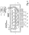
- FIGURE 3 depicts a single elongated x-ray tube 40 capable of generating n parallel fan-shaped x-ray beams 30 1 , 30 2 ,...30 n .
- the beams 30 1 , 30 2 ,...30 n are generated and collimated by a collimator 42 .
- the collimator 42 is disposed adjacent to the x-ray beam source and channels the beams 30 1 , 30 2 ,...30 n into a series of parallel axially spaced fan-shaped rays.
- the beams are attenuated as they pass through a subject 44 and are received by the plurality of axially spaced detector arrays 14 1 , 14 2 ,...14 n .
- the detector arrays 14 1 , 14 2 ,...14 n generate electrical signals each proportional to the radiation received along a corresponding ray of each fan.
- the detector arrays could be configured as semi-circular arcs (15) sufficient to receive the x-ray beam arc and could further be rotatably mounted to the rotating gantry portion in a third generation scanner (as shown in FIGURE 2).
- the axially elongated x-ray tube 40 houses a plurality of rotating anode elements 60 1 , 60 2 ,...60 n .
- Each anode element 60 1 , 60 2 ,...60 n is associated with a cathode assembly 70 1 , 70 2 ,...70 n , selectably excitable by a filament power supply 80 .
- each cathode assembly When selected, each cathode assembly generates an electron stream which strikes the corresponding anode element and produces x-ray beams.
- the x-ray beams are collimated by the collimator 42 into the plurality of parallel axially spaced x-ray beams 30 1 , 30 2 ,...30 n .
- the radiation source generates axially spaced parallel x-ray beams 82 1 , 82 2 ,...82 n that are angularly spaced from one another with respect to the examination region 12 .
- a plurality of x-ray tubes 90 1 , 90 2 ,...90 n are mounted onto the rotating gantry C .
- the x-ray sources are evenly angularly separated at 120° intervals about the examination region 12 , but may be spaced at any offset angle.
- the fan beams 82 1 , 82 2 , 82 3 are received by the detector array 14 in specific, isolated areas 84 1 , 84 2 , 84 3 .
- FIGURE 7 depicts a cross-section of the CT scanner of FIGURE 6 to depict more clearly the axial separation of the x-ray tubes 90 1 , 90 2 , 90 3 .
- a singe substantially continuous detector array 14 is mounted to the stationary gantry portion A to receive the x-ray beams generated by the x-ray tubes 90 1 , 90 2 , 90 3 .
- the x-ray beams 82 1 , 82 2 , 82 3 are closely collimated to strike the single detector array 14 in locations angularly displaced from one another.
- each x-ray beam 82 1 , 82 2 , 82 3 is received by the detector array 14 over a unique arc 84 1 , 84 2 , 84 3 .
- the x-ray beams 82 1 , 82 2 , 82 3 do not overlap, so that the single detector array 14 can produce signals representative of the three separate beams.
- a plurality of multiple anode element tubes are mounted in intervals around a plurality of rings of radiation detectors 14 1 , 14 2 ,...14 n as illustrated in FIGURE 3.
- the x-ray sources are spaced an appropriate distance such that each fan beam irradiates a unique arc segment of one of the rings.
- three of the x-ray sources can be disposed about 120° apart around the examination region.
- a larger number of multiple anode x-ray tubes may be positioned around the subject and the various anodes gated on and off to prevent more than one beam from irradiating a common detector element of one of the rings.
- the x-ray tube assembly preferably includes a control circuit 100 for selectively powering the cathode assemblies 70 .
- a cathode controller 102 is electrically connected between the filament current supply 80 and the individual cathode assemblies 70 .
- the cathode controller 102 can be configured as a grid control tube, electrical switch circuit, or the like.
- a comparator 104 controls the cathode controller 102 based on selected inputs.
- the selected inputs include a profile input 106 , a thermal profile memory or look up table 108 , and a timer 110 .
- the profile input 106 is preferably an input source where a technician can select a desired imaging pattern based on diagnostic needs.
- the profile input desired may be for all multiple fan beams to be used simultaneously providing a maximum number of image slices in the shortest time.
- the desired profile may be to alternate or cycle selected sub-sets of multiple fan beams, perhaps to cover a larger volume.
- the technician may desire a maximum number of slices within the temperature envelope of the x-ray tube assembly.
- the thermal profile memory 108 is accessed to estimate the time that the anode elements can be bombarded with electrons before a period of rest, or non-use must occur to facilitate removal of excess thermal energy.
- the memory 108 is preloaded with thermal curves specific to the anode elements of the tube.
- a timer 110 calculates the amount of time the individual cathodes have been on. This time allows the comparator to estimate thermal loading conditions of the anode elements in use by plotting the time onto the thermal profile memory.
- the comparator 104 receives the inputs, determines the sequence of operation and controls the cathode controller 102 to individually select specific cathode assemblies 70 .
- the illustrated multiple fan beam computed tomography system has a number of advantages.
- One advantage resides in significantly improved imaging time as compared with conventional single fan beam CT systems.
- Another advantage is that volumes can be imaged substantially in real time.
- Another advantage resides in the ability to use existing reconstruction algorithms to generate images.
Abstract
Description
- The present invention relates to computed tomography (CT), especially for diagnostic imaging. The invention finds particular application in conjunction with volume CT imaging for medical purposes and will be described with particular reference thereto. However, it is to be appreciated that the present invention will also find application in conjunction with industrial, security, and other types of volume imaging apparatus and techniques.
- In diagnostic imaging with CT scanners, a thin, fan shaped beam of radiation is projected from an x-ray source through a region of interest. The radiation source is rotated about the region of interest such that the same thin slice of the region of interest is irradiated from a multiplicity of directions spanning 360°. In a third generation scanner, an arc of radiation detectors is mounted to the same gantry as the radiation source such that the two rotate together. In a fourth generation scanner, the x-ray detectors are mounted stationarily in a ring 360° around the subject.
- To image a volume of interest, a single slice image is typically generated. After a first slice image is generated, a subject support is indexed by a slice width generally on the order of a few millimetres, and another slice is generated. This slice image and index technique is repeated until slices spanning the volume of interest are generated. One drawback to this type of imaging is the relatively long time necessary to generate a large plurality of slices. Because the first and last slice are taken at a significantly different time, the volume image is distorted by a time evolution of the region of interest.
- In spiral scanning techniques, the patient is generally moved continuously through the x-ray beam as the x-ray source rotates around the region of interest. In this manner, the fan shaped beam of radiation and the region of interest move in a spiral pattern relative to each other. The continuous motion is faster than indexing between slices, but still relatively slow.
- In order to reduce the imaging time, some scanners collimate the beam of radiation into two slices. When the beam of radiation is collimated into two slices, two sets of radiation detectors disposed end to end are commonly provided. Typically, the thickness of the irradiated slice and the spacing between slices are adjustable. Such adjustments are relatively straightforward for two beams of radiation. However, the requirement that each beam of radiation strike only a single set of radiation detectors renders collimation into more than two beams mechanically awkward. Moreover, because the two beams originate from a common focal point, they are divergent, not parallel to each other. The divergent rays complicate and introduce errors into reconstruction techniques in which data is reconstructed into parallel slices. Moreover, as radiation from a single source is collimated into more beams, such beams become more widely divergent.
- Systems have been proposed for examining the region of interest with a cone beam of radiation. However, cone beam image reconstruction is computationally intensive and slow. Moreover, cone beam imaging has a fixed resolution, based on detector size. Further, cone beam reconstructions tend to suffer from insufficiency of data problems, image artifacts, and other reconstruction errors.
- In accordance with the present invention, a CT scanner includes a stationary gantry portion defining an examination region. A rotating gantry portion selectively rotates about the examination region. A plurality of anode elements, associated with the rotating gantry portion for selective bombardment by an electron stream, generate a plurality of parallel x-ray beams. A plurality of x-ray detectors receive the x-ray beams which have passed through the examination region. The detectors generate signals indicative of the x-ray beams received and a reconstruction processor processes these generated signals into an image representation.
- In accordance with the present invention, a method of diagnostic imaging includes concurrently generating a plurality of thin fan beams of penetrating radiation. The plurality of thin fan beams are passed through an examination region while the fan beams are concurrently rotating around the examination region. Each of the fan beams is detected after passing through the examination region and are used to generate electronic signals indicative of an amount of radiation which has passed through the examination region.
- Ways of carrying out the invention will now be described in detail, by way of example, with reference to the accompanying drawings, in which:
- FIGURE 1 is a perspective view of a continuous CT scanner system in accordance with the present invention;
- FIGURE 2 is a diagrammatic illustration of a set of x-ray beams produced according to the present invention;
- FIGURE 3 is a detail of a fourth generation CT scanner in accordance with the present invention;
- FIGURE 4 is a cross-section of a multiple anode x-ray tube suitable to meet the present invention;
- FIGURE 5 is a diagrammatic illustration of an alternate set of x-ray beams produced in accordance with the present invention;
- FIGURE 6 is a detail of an alternate embodiment of a fourth generation scanner according to the present invention;
- FIGURE 7 is a cross-section of the scanner from FIGURE 6; and
- FIGURE 8 is a block diagram of an exemplary control circuit suitable to practice the present invention.
-
- With reference to FIGURE 1, a CT scanner includes a floor mounted or stationary gantry A whose position remains fixed during data collection. A multiple fan beam generator B is rotatably mounted on a rotating gantry C. The stationary gantry A includes a
cylinder 10 that defines apatient receiving region 12. A plurality of rings ofradiation detectors patient receiving region 12. In the illustrated embodiment, the radiation detectors are mounted on the stationary gantry portion such that a corresponding arc segment of the detectors receives each fan beam of radiation from the radiation source B which has traversed a corresponding parallel path through theexamination region 12. Alternately, as illustrated in Figure 2, a plurality of arc segments of radiation detectors can be mounted to the rotating gantry portion C each in alignment with one of the fan beams to rotate with the x-ray source. - A
control console 16 contains animage reconstruction processor 18 for reconstructing a volumetric image representation using signals from thedetector array monitor 20. - The
reconstruction processor 18 includes a plurality ofreconstruction processors stationary detector rings detector rings corresponding processor volume image memory 22. If the x-ray beams are spaced immediately contiguous, then all of the slices of the volume image are reconstructed concurrently. However, in the preferred embodiment, the number of slices is less than the total number of slices in the volume and the slices are spread apart such that some fraction of the slices, e.g. every sixth slice, is generated concurrently. Thereafter, apatient couch 24 is stepped one slice distance and the next set of slices is generated concurrently. In the present example in which one sixth of the slices is taken each time, this process is repeated six times. - In another preferred embodiment, the slices are again spaced by some short distance. The patient table 24 moves in either direction through the imaging area or back and forth continuously as the x-ray beams rotate continuously. The motion of the patient table is selected such that the data collected by each of the radiation detectors spirals in each of a plurality of contiguous slabs. The data in each of the slabs is reconstructed, preferably concurrently by a plurality of parallel processors, using conventional spiral volume imaging algorithms.
- In yet another alternate embodiment, the patient table moves back and forth a sufficient distance that the spirals overlap. The conventional spiral imaging algorithm is modified such that each of a series of preferably parallel processors is updating a corresponding region of
volume image memory 22, concurrently. - The
video monitor 20 converts selectable portions of the reconstructed volumetric image representation into a two-dimensional human-readable display. Theconsole 16 also includes appropriate tape or disk recording devices, performing image enhancements, selecting planes for viewing, 3-D renderings, or colour enhancements or the like. Various scanner control functions such as initiating a scan, selecting among different types of scans, calibrating the system and the like are also performed at the control console. - With reference to FIGURES 1 and 2, the x-ray generator B is elongated along an axis parallel to the
examination region 12. Multiple parallel fan-shapedbeams beams examination region 12 and radiation data is collected by the detectors 15. Volume scans are achieved by axially moving thecouch 24 or region of interest through theexamination region 12 and the plurality of x-ray beams 301, 302,...30n . Any number of x-ray beams may be generated, and the time required for a volume scan or coverage time is reduced by a factor proportional to the number of x-ray beams used. - FIGURE 3 depicts a single
elongated x-ray tube 40 capable of generating n parallel fan-shaped x-ray beams 301, 302,...30n . Thebeams collimator 42. Thecollimator 42 is disposed adjacent to the x-ray beam source and channels thebeams detector arrays detector arrays - Cross-referencing FIGURE 3 and FIGURE 4, the axially elongated
x-ray tube 40 houses a plurality of rotating anode elements 601, 602,...60n . Each anode element 601, 602,...60n is associated with acathode assembly filament power supply 80. When selected, each cathode assembly generates an electron stream which strikes the corresponding anode element and produces x-ray beams. The x-ray beams are collimated by thecollimator 42 into the plurality of parallel axially spaced x-ray beams 301, 302,...30n. - Alternatively, as seen in FIGURE 5, the radiation source generates axially spaced parallel x-ray beams 821, 822,...82n that are angularly spaced from one another with respect to the
examination region 12. In the embodiment of Figure 6, a plurality of x-ray tubes 901, 902,...90n are mounted onto the rotating gantry C. In a preferred embodiment in which n=3, the x-ray sources are evenly angularly separated at 120° intervals about theexamination region 12, but may be spaced at any offset angle. The fan beams 821, 822, 823 are received by thedetector array 14 in specific, isolated areas 841, 842, 843. - FIGURE 7 depicts a cross-section of the CT scanner of FIGURE 6 to depict more clearly the axial separation of the x-ray tubes 901, 902, 903 . In the embodiment of Figures 6 and 7, a singe substantially
continuous detector array 14 is mounted to the stationary gantry portion A to receive the x-ray beams generated by the x-ray tubes 901, 902, 903 . The x-ray beams 821, 822, 823 are closely collimated to strike thesingle detector array 14 in locations angularly displaced from one another. Moreover, because the x-ray tubes are angularly spaced about theexamination region 12, eachx-ray beam detector array 14 over a unique arc 841, 842, 843 . In other words, the x-ray beams 821, 822, 823 do not overlap, so that thesingle detector array 14 can produce signals representative of the three separate beams. - In an alternate embodiment, a plurality of multiple anode element tubes, such as are illustrated by
reference number 40 in FIGURE 4, are mounted in intervals around a plurality of rings ofradiation detectors - Referring now to FIGURE 8 the x-ray tube assembly preferably includes a
control circuit 100 for selectively powering thecathode assemblies 70. Acathode controller 102 is electrically connected between the filamentcurrent supply 80 and theindividual cathode assemblies 70. Thecathode controller 102 can be configured as a grid control tube, electrical switch circuit, or the like. Acomparator 104 controls thecathode controller 102 based on selected inputs. Preferably the selected inputs include aprofile input 106, a thermal profile memory or look up table 108, and atimer 110. Theprofile input 106 is preferably an input source where a technician can select a desired imaging pattern based on diagnostic needs. For example, the profile input desired may be for all multiple fan beams to be used simultaneously providing a maximum number of image slices in the shortest time. On the other hand, the desired profile may be to alternate or cycle selected sub-sets of multiple fan beams, perhaps to cover a larger volume. - As a further example, the technician may desire a maximum number of slices within the temperature envelope of the x-ray tube assembly. In this event, the
thermal profile memory 108 is accessed to estimate the time that the anode elements can be bombarded with electrons before a period of rest, or non-use must occur to facilitate removal of excess thermal energy. Thememory 108 is preloaded with thermal curves specific to the anode elements of the tube. Then, when the tubes are powered, atimer 110 calculates the amount of time the individual cathodes have been on. This time allows the comparator to estimate thermal loading conditions of the anode elements in use by plotting the time onto the thermal profile memory. - Regardless of profile desired, the
comparator 104 receives the inputs, determines the sequence of operation and controls thecathode controller 102 to individually selectspecific cathode assemblies 70. - The illustrated multiple fan beam computed tomography system has a number of advantages. One advantage resides in significantly improved imaging time as compared with conventional single fan beam CT systems. Another advantage is that volumes can be imaged substantially in real time. Another advantage resides in the ability to use existing reconstruction algorithms to generate images.
Claims (10)
- A CT scanner comprising: a stationary gantry (A) portion defining an examination region (12); a rotatable gantry (C) portion for selectively rotating about the examination region (12); a plurality of anode elements (60) associated with the rotatable gantry portion (C) for selective bombardment by an electron stream generating a plurality of parallel x-ray beams (30); a plurality of x-ray detectors (14) receiving the x-ray beams (30) which have passed through the examination region (12) and generating signals indicative of the x-ray beams received; and a reconstruction processor (18) processing the generated signals into an image representation.
- A CT scanner as claimed in claim 1, further including: a plurality of x-ray tubes (40) each including at least one of the plurality of anode elements (60) having at least one target face associated with at least one cathode assembly (70) disposed within a vacuum housing, the cathode assembly (70) being controlled by a controller (102) in response to a control signal selectively generating the electron stream, each x-ray tube being mounted to the rotating gantry portion (C), and spaced along an axis at a common angle relative to the examination region (12); and at least one collimator (42) externally adjacent to one of the x-ray tubes (40), where the collimator defines an opening having fan-shaped sides forming parallel fan-shaped x-ray beams (30).
- A CT scanner as claimed in claim 1, further including: a plurality of x-ray tubes (90) each comprising one of the plurality of anode elements having at least one target face associated with at least one cathode assembly disposed within a vacuum housing, the cathode assembly being controlled by a controller (102) in response to the control signal selectively generating the electron stream, wherein each x-ray tube is mounted to the rotating gantry (C) portion, the x-ray tubes (90) spaced along an axis at a plurality of predefined angles relative to the examination region (12); and a collimator externally adjacent to each of the x-ray tubes (90), where the collimator defines an opening having fan-shaped sides forming parallel fan-shaped x-ray beams (82).
- A CT scanner as claimed in any one of claims 1 to 3, wherein the plurality of x-ray detectors comprise a set of axially spaced continuous rings of detector elements (14) mounted to the stationary gantry (A) portion.
- A CT scanner as claimed in any one of claims 1 to 3, wherein the plurality of x-ray detectors comprise axially spaced arcs of detector elements (15) mounted to the rotating gantry (C) portion, each arc opposite an apex of the x-ray beams (30).
- A method of diagnostic imaging comprising: concurrently generating a plurality of thin fan beams (30) of penetrating radiation; passing the plurality of thin fan beams (30) of penetrating radiation through an examination region (12) and concurrently rotating the fan beams (30) around the examination region (12); detecting each of the fan beams (30) of radiation after it has passed through the examination region (12) and generating electronic signals indicative of an amount of radiation which passed through the examination region (12); and reconstructing electronic signals into a volumetric image representation.
- A method as claimed in claim 6, wherein the fan beams (30) of radiation are rotated about an axis of rotation and further including: causing relative axial movement along the axis (2) of rotation between the examination region and the parallel fan beams (30) of radiation.
- A method as claimed in claim 6 or claim 7, wherein the thin fan beams (30) of radiation are parallel to others of the thin fan beams (30) and rotate about an axis of rotation and further including: continuously moving the examination region (12) and the parallel thin fan beams (30) of radiation along the axis (2) of rotation such that each of the parallel beams (30) of radiation traverse a spiral through the examination region.
- A method as claimed in any one of claims 6 to 8, wherein the fan shaped beams (30) of radiation rotate about an axis (2) of rotation and wherein an apex of each of the fan shaped beams (30) lies along a common line parallel to the axis (2) of rotation.
- A method as claimed in any one of claims 6 to 9, wherein an apex of at least some of the fan beams (82) is angularly offset around an axis (2) of rotation relative to an apex of others of the fan beams (82).
Applications Claiming Priority (2)
| Application Number | Priority Date | Filing Date | Title |
|---|---|---|---|
| US09/199,733 US6229870B1 (en) | 1998-11-25 | 1998-11-25 | Multiple fan beam computed tomography system |
| US199733 | 2002-07-19 |
Publications (2)
| Publication Number | Publication Date |
|---|---|
| EP1005257A2 true EP1005257A2 (en) | 2000-05-31 |
| EP1005257A3 EP1005257A3 (en) | 2003-06-11 |
Family
ID=22738789
Family Applications (1)
| Application Number | Title | Priority Date | Filing Date |
|---|---|---|---|
| EP99308855A Withdrawn EP1005257A3 (en) | 1998-11-25 | 1999-11-08 | Computed tomography |
Country Status (3)
| Country | Link |
|---|---|
| US (1) | US6229870B1 (en) |
| EP (1) | EP1005257A3 (en) |
| JP (1) | JP2000175895A (en) |
Cited By (13)
| Publication number | Priority date | Publication date | Assignee | Title |
|---|---|---|---|---|
| FR2819141A1 (en) * | 2000-12-29 | 2002-07-05 | Chabunda Christophe Mwanza | 2D/3D diagnostic X ray radiology having vacuum chamber with central double rotating target end producing two distinct/same/electron beams and output windows ceramic outer held. |
| EP1396715A1 (en) * | 2002-08-20 | 2004-03-10 | General Electric Company | Multiple focal spot x-ray inspection system |
| WO2005004722A2 (en) | 2003-07-15 | 2005-01-20 | Koninklijke Philips Electronics N.V. | Computed tomography scanner with large gantry bore |
| EP1570785A1 (en) * | 2004-03-02 | 2005-09-07 | GE Medical Systems Global Technology Company LLC | X-ray ct system and x-ray apparatus |
| WO2006090323A2 (en) * | 2005-02-24 | 2006-08-31 | Philips Intellectual Property & Standards Gmbh | Computer tomography apparatus with multiple x-ray radiation sources |
| WO2006135837A1 (en) * | 2005-06-10 | 2006-12-21 | Xoran Technologies, Inc. | Multiple source ct scanner |
| US7399973B2 (en) | 2004-03-19 | 2008-07-15 | Imaging Pet Technologies, Inc. | System for medical diagnosis |
| US7456407B2 (en) | 2004-03-19 | 2008-11-25 | Is2 Medical Systems Inc. | System for medical imaging and a patient support system for medical diagnosis |
| EP2083694A1 (en) * | 2006-11-09 | 2009-08-05 | Canon Kabushiki Kaisha | Radiographic imaging control apparatus using multi radiation generating apparatus |
| CN105678823A (en) * | 2016-02-02 | 2016-06-15 | 北京航空航天大学 | Multiple two-dimensional fan-beam computer chromatography method |
| CN106526686A (en) * | 2016-12-07 | 2017-03-22 | 同方威视技术股份有限公司 | Spiral CT equipment and three-dimensional image reconstruction method |
| CN107202801A (en) * | 2016-03-16 | 2017-09-26 | 临沂大学 | A kind of computed tomograph scanner system |
| CN113520415A (en) * | 2020-04-20 | 2021-10-22 | 上海联影医疗科技股份有限公司 | X-ray image acquisition method and system |
Families Citing this family (68)
| Publication number | Priority date | Publication date | Assignee | Title |
|---|---|---|---|---|
| IL148871A0 (en) * | 2000-09-28 | 2002-09-12 | Philips Medical Systems Techno | Ct scanner for time-coherent large coverage |
| US7072436B2 (en) * | 2001-08-24 | 2006-07-04 | The Board Of Trustees Of The Leland Stanford Junior University | Volumetric computed tomography (VCT) |
| US7813473B2 (en) * | 2002-07-23 | 2010-10-12 | General Electric Company | Method and apparatus for generating temporally interpolated projections |
| US6904118B2 (en) * | 2002-07-23 | 2005-06-07 | General Electric Company | Method and apparatus for generating a density map using dual-energy CT |
| GB0525593D0 (en) | 2005-12-16 | 2006-01-25 | Cxr Ltd | X-ray tomography inspection systems |
| US10483077B2 (en) | 2003-04-25 | 2019-11-19 | Rapiscan Systems, Inc. | X-ray sources having reduced electron scattering |
| US8094784B2 (en) | 2003-04-25 | 2012-01-10 | Rapiscan Systems, Inc. | X-ray sources |
| GB0309383D0 (en) * | 2003-04-25 | 2003-06-04 | Cxr Ltd | X-ray tube electron sources |
| US9208988B2 (en) | 2005-10-25 | 2015-12-08 | Rapiscan Systems, Inc. | Graphite backscattered electron shield for use in an X-ray tube |
| GB0812864D0 (en) | 2008-07-15 | 2008-08-20 | Cxr Ltd | Coolign anode |
| US8243876B2 (en) | 2003-04-25 | 2012-08-14 | Rapiscan Systems, Inc. | X-ray scanners |
| DE10322137A1 (en) * | 2003-05-16 | 2004-12-16 | Siemens Ag | X-ray machine with improved efficiency |
| US7120222B2 (en) * | 2003-06-05 | 2006-10-10 | General Electric Company | CT imaging system with multiple peak x-ray source |
| EP1649482B1 (en) * | 2003-07-18 | 2009-04-15 | Koninklijke Philips Electronics N.V. | Cylindrical x-ray tube for computed tomography imaging |
| DE10337935A1 (en) * | 2003-08-18 | 2005-03-17 | Siemens Ag | Device for recording structural data of an object |
| US20050100126A1 (en) * | 2003-11-07 | 2005-05-12 | Mistretta Charles A. | Computed tomography with z-axis scanning |
| US7639774B2 (en) * | 2003-12-23 | 2009-12-29 | General Electric Company | Method and apparatus for employing multiple axial-sources |
| US7333587B2 (en) * | 2004-02-27 | 2008-02-19 | General Electric Company | Method and system for imaging using multiple offset X-ray emission points |
| DE102004018498A1 (en) * | 2004-04-14 | 2005-11-17 | Siemens Ag | Operating method for an X-ray system, computer-aided determination method for at least one 3D reconstruction of an object and devices corresponding thereto |
| FR2872295B1 (en) * | 2004-06-28 | 2007-02-09 | Commissariat Energie Atomique | TOMOGRAPHY WITH SPECIFIC SHAPE DETECTORS |
| DE102004037076B4 (en) * | 2004-07-30 | 2011-02-24 | Siemens Ag | Gantry and computed tomography |
| US7103138B2 (en) * | 2004-08-24 | 2006-09-05 | The Board Of Trustees Of The Leland Stanford Junior University | Sampling in volumetric computed tomography |
| US7062006B1 (en) * | 2005-01-19 | 2006-06-13 | The Board Of Trustees Of The Leland Stanford Junior University | Computed tomography with increased field of view |
| CN100574827C (en) * | 2005-08-25 | 2009-12-30 | 深圳市海博科技有限公司 | Radiotherapy unit |
| US9046465B2 (en) | 2011-02-24 | 2015-06-02 | Rapiscan Systems, Inc. | Optimization of the source firing pattern for X-ray scanning systems |
| US7496181B2 (en) * | 2005-11-28 | 2009-02-24 | The Board Of Trustees Of The Leland Stanford Junior University | X-ray collimator for imaging with multiple sources and detectors |
| WO2007070580A2 (en) * | 2005-12-12 | 2007-06-21 | Reveal Imaging Technologies | Displaced-ray ct inspection |
| WO2007120744A2 (en) * | 2006-04-14 | 2007-10-25 | William Beaumont Hospital | Scanning slot cone-beam computed tomography and scanning focus spot cone-beam computed tomography |
| US9339243B2 (en) | 2006-04-14 | 2016-05-17 | William Beaumont Hospital | Image guided radiotherapy with dual source and dual detector arrays tetrahedron beam computed tomography |
| US8983024B2 (en) | 2006-04-14 | 2015-03-17 | William Beaumont Hospital | Tetrahedron beam computed tomography with multiple detectors and/or source arrays |
| EP2026698A4 (en) * | 2006-05-25 | 2016-10-05 | Beaumont Hospital William | Real-time, on-line and offline treatment dose tracking and feedback process for volumetric image guided adaptive radiotherapy |
| CN101495886B (en) * | 2006-08-01 | 2012-11-07 | 皇家飞利浦电子股份有限公司 | Stereo tube computed tomography |
| US7616731B2 (en) * | 2006-08-30 | 2009-11-10 | General Electric Company | Acquisition and reconstruction of projection data using a stationary CT geometry |
| US20080056432A1 (en) * | 2006-08-30 | 2008-03-06 | General Electric Company | Reconstruction of CT projection data |
| US7835486B2 (en) * | 2006-08-30 | 2010-11-16 | General Electric Company | Acquisition and reconstruction of projection data using a stationary CT geometry |
| US7706499B2 (en) * | 2006-08-30 | 2010-04-27 | General Electric Company | Acquisition and reconstruction of projection data using a stationary CT geometry |
| WO2008122970A1 (en) * | 2007-04-10 | 2008-10-16 | Arineta Ltd. | X-ray tube plurality of targets and corresponding number of electron beam gates |
| US8537965B2 (en) * | 2007-04-10 | 2013-09-17 | Arineta Ltd. | Cone-beam CT |
| WO2008122971A1 (en) * | 2007-04-10 | 2008-10-16 | Arineta Ltd. | Cone-beam ct |
| US7809101B2 (en) | 2008-06-06 | 2010-10-05 | General Electric Company | Modular multispot X-ray source and method of making same |
| WO2010016107A1 (en) * | 2008-08-05 | 2010-02-11 | 株式会社島津製作所 | Pet instrument |
| GB0816823D0 (en) | 2008-09-13 | 2008-10-22 | Cxr Ltd | X-ray tubes |
| JP4693884B2 (en) * | 2008-09-18 | 2011-06-01 | キヤノン株式会社 | Multi X-ray imaging apparatus and control method thereof |
| US20100080357A1 (en) * | 2008-10-01 | 2010-04-01 | General Electric Company | Wide coverage x-ray tube and ct system |
| GB0901338D0 (en) | 2009-01-28 | 2009-03-11 | Cxr Ltd | X-Ray tube electron sources |
| DE102009020400B4 (en) * | 2009-05-08 | 2016-04-21 | Siemens Aktiengesellschaft | Method and apparatus for image determination from x-ray projections taken when traversing a trajectory |
| US8204174B2 (en) * | 2009-06-04 | 2012-06-19 | Nextray, Inc. | Systems and methods for detecting an image of an object by use of X-ray beams generated by multiple small area sources and by use of facing sides of adjacent monochromator crystals |
| DE102009043423A1 (en) * | 2009-09-29 | 2011-04-21 | Siemens Aktiengesellschaft | X-ray procedure and X-ray recording system |
| CA2785995A1 (en) | 2010-01-05 | 2011-07-14 | William Beaumont Hospital | Intensity modulated arc therapy with continuous couch rotation/shift and simultaneous cone beam imaging |
| US9271689B2 (en) * | 2010-01-20 | 2016-03-01 | General Electric Company | Apparatus for wide coverage computed tomography and method of constructing same |
| US20120087464A1 (en) * | 2010-10-09 | 2012-04-12 | Fmi Technologies, Inc. | Multi-source low dose x-ray ct imaging aparatus |
| JP5201515B2 (en) * | 2011-01-06 | 2013-06-05 | つくばテクノロジー株式会社 | X-ray nondestructive inspection equipment |
| DE102011004747B4 (en) * | 2011-02-25 | 2019-05-23 | Siemens Healthcare Gmbh | Medical imaging device having at least two devices for identifying one plane in space at a time |
| WO2013163256A1 (en) * | 2012-04-26 | 2013-10-31 | American Science And Engineering, Inc. | X-ray tube with rotating anode aperture |
| CN103674979B (en) * | 2012-09-19 | 2016-12-21 | 同方威视技术股份有限公司 | A kind of luggage and articles CT safe examination system and detector assembly thereof |
| KR20150024720A (en) * | 2013-08-27 | 2015-03-09 | 삼성전자주식회사 | Flat panel tpye X-ray generator and X-ray imaging system having the X-ray generator |
| CN103961129B (en) * | 2013-09-11 | 2016-03-30 | 梁月强 | Rotating grating conical beam CT |
| US9976971B2 (en) * | 2014-03-06 | 2018-05-22 | United Technologies Corporation | Systems and methods for X-ray diffraction |
| KR101609932B1 (en) * | 2014-07-02 | 2016-04-06 | (의료)길의료재단 | Curved movable beam stop array and CBCT comprising thereof |
| WO2016047989A1 (en) * | 2014-09-23 | 2016-03-31 | Samsung Electronics Co., Ltd. | Apparatus for processing medical image and method of processing medical image thereof |
| KR101747306B1 (en) * | 2014-09-23 | 2017-06-14 | 삼성전자주식회사 | Apparatus for photographing medical image and method for processing an medical image thereof |
| US10157481B2 (en) | 2014-09-23 | 2018-12-18 | Samsung Electronics Co., Ltd. | Apparatus for processing medical image and method of processing medical image thereof |
| WO2019090314A1 (en) | 2017-11-06 | 2019-05-09 | The Research Foundation for State University of New York | System and method for dual-use computed tomography for imaging and radiation therapy |
| EP3938768A4 (en) * | 2019-03-15 | 2022-05-04 | Robotic Technologies Limited | X-ray imaging system, method and shutter |
| FR3102055B1 (en) * | 2019-10-17 | 2024-03-08 | Thales Sa | Radiology device with several sources of ionizing rays and method using the device |
| CN115096922A (en) * | 2021-07-07 | 2022-09-23 | 清华大学 | Ray scanning device |
| CN115097535A (en) * | 2021-07-07 | 2022-09-23 | 清华大学 | Inspection system and method |
| CN115356359B (en) * | 2022-08-26 | 2023-06-13 | 清华大学 | Laser acceleration driven high-energy micro-focus X-ray large-field CT imaging device |
Citations (4)
| Publication number | Priority date | Publication date | Assignee | Title |
|---|---|---|---|---|
| GB1528574A (en) * | 1975-10-27 | 1978-10-11 | Emi Ltd | Radiography |
| EP0025982A2 (en) * | 1979-09-21 | 1981-04-01 | Siemens Aktiengesellschaft | Device for producing transverse tomographic images of a recordable object |
| DE3109100A1 (en) * | 1981-03-10 | 1982-09-30 | Siemens AG, 1000 Berlin und 8000 München | X-ray instrument |
| DE4224249A1 (en) * | 1991-07-24 | 1993-01-28 | Elscint Ltd | Multiple-disc computer tomography scanning system - moves detectors axially relative to source while rotating both around body to provide spiral scan |
Family Cites Families (13)
| Publication number | Priority date | Publication date | Assignee | Title |
|---|---|---|---|---|
| FR2415876A1 (en) * | 1978-01-27 | 1979-08-24 | Radiologie Cie Gle | X-RAY TUBE, ESPECIALLY FOR TOMODENSITOMETER |
| US5485493A (en) | 1988-10-20 | 1996-01-16 | Picker International, Inc. | Multiple detector ring spiral scanner with relatively adjustable helical paths |
| US5241577A (en) | 1992-01-06 | 1993-08-31 | Picker International, Inc. | X-ray tube with bearing slip ring |
| US5305363A (en) | 1992-01-06 | 1994-04-19 | Picker International, Inc. | Computerized tomographic scanner having a toroidal x-ray tube with a stationary annular anode and a rotating cathode assembly |
| US5268955A (en) | 1992-01-06 | 1993-12-07 | Picker International, Inc. | Ring tube x-ray source |
| US5274690A (en) | 1992-01-06 | 1993-12-28 | Picker International, Inc. | Rotating housing and anode/stationary cathode x-ray tube with magnetic susceptor for holding the cathode stationary |
| DE69213202T2 (en) | 1992-01-06 | 1997-01-23 | Picker Int Inc | X-ray tube with ferrite core filament transformer |
| US5200985A (en) | 1992-01-06 | 1993-04-06 | Picker International, Inc. | X-ray tube with capacitively coupled filament drive |
| US5335255A (en) * | 1992-03-24 | 1994-08-02 | Seppi Edward J | X-ray scanner with a source emitting plurality of fan beams |
| US5966422A (en) * | 1992-07-20 | 1999-10-12 | Picker Medical Systems, Ltd. | Multiple source CT scanner |
| US5467377A (en) * | 1994-04-15 | 1995-11-14 | Dawson; Ralph L. | Computed tomographic scanner |
| US5712889A (en) * | 1994-08-24 | 1998-01-27 | Lanzara; Giovanni | Scanned volume CT scanner |
| US5592523A (en) | 1994-12-06 | 1997-01-07 | Picker International, Inc. | Two dimensional detector array for CT scanners |
-
1998
- 1998-11-25 US US09/199,733 patent/US6229870B1/en not_active Expired - Fee Related
-
1999
- 1999-11-08 EP EP99308855A patent/EP1005257A3/en not_active Withdrawn
- 1999-11-25 JP JP11335047A patent/JP2000175895A/en active Pending
Patent Citations (4)
| Publication number | Priority date | Publication date | Assignee | Title |
|---|---|---|---|---|
| GB1528574A (en) * | 1975-10-27 | 1978-10-11 | Emi Ltd | Radiography |
| EP0025982A2 (en) * | 1979-09-21 | 1981-04-01 | Siemens Aktiengesellschaft | Device for producing transverse tomographic images of a recordable object |
| DE3109100A1 (en) * | 1981-03-10 | 1982-09-30 | Siemens AG, 1000 Berlin und 8000 München | X-ray instrument |
| DE4224249A1 (en) * | 1991-07-24 | 1993-01-28 | Elscint Ltd | Multiple-disc computer tomography scanning system - moves detectors axially relative to source while rotating both around body to provide spiral scan |
Cited By (21)
| Publication number | Priority date | Publication date | Assignee | Title |
|---|---|---|---|---|
| FR2819141A1 (en) * | 2000-12-29 | 2002-07-05 | Chabunda Christophe Mwanza | 2D/3D diagnostic X ray radiology having vacuum chamber with central double rotating target end producing two distinct/same/electron beams and output windows ceramic outer held. |
| EP1396715A1 (en) * | 2002-08-20 | 2004-03-10 | General Electric Company | Multiple focal spot x-ray inspection system |
| US6895079B2 (en) | 2002-08-20 | 2005-05-17 | General Electric Company | Multiple focal spot X-ray inspection system |
| US7324623B2 (en) | 2003-07-15 | 2008-01-29 | Koninklijke Philips Electronics N. V. | Computed tomography scanner with large gantry bore |
| WO2005004722A2 (en) | 2003-07-15 | 2005-01-20 | Koninklijke Philips Electronics N.V. | Computed tomography scanner with large gantry bore |
| WO2005004722A3 (en) * | 2003-07-15 | 2005-04-14 | Koninkl Philips Electronics Nv | Computed tomography scanner with large gantry bore |
| EP1570785A1 (en) * | 2004-03-02 | 2005-09-07 | GE Medical Systems Global Technology Company LLC | X-ray ct system and x-ray apparatus |
| US7399973B2 (en) | 2004-03-19 | 2008-07-15 | Imaging Pet Technologies, Inc. | System for medical diagnosis |
| US7456407B2 (en) | 2004-03-19 | 2008-11-25 | Is2 Medical Systems Inc. | System for medical imaging and a patient support system for medical diagnosis |
| US7627081B2 (en) | 2005-02-24 | 2009-12-01 | Koninklijke Philips Electronics N.V. | Computer tomography apparatus with multiple x-ray radiation sources |
| WO2006090323A3 (en) * | 2005-02-24 | 2006-11-09 | Philips Intellectual Property | Computer tomography apparatus with multiple x-ray radiation sources |
| WO2006090323A2 (en) * | 2005-02-24 | 2006-08-31 | Philips Intellectual Property & Standards Gmbh | Computer tomography apparatus with multiple x-ray radiation sources |
| WO2006135837A1 (en) * | 2005-06-10 | 2006-12-21 | Xoran Technologies, Inc. | Multiple source ct scanner |
| EP2083694A4 (en) * | 2006-11-09 | 2010-03-10 | Canon Kk | Radiographic imaging control apparatus using multi radiation generating apparatus |
| EP2083694A1 (en) * | 2006-11-09 | 2009-08-05 | Canon Kabushiki Kaisha | Radiographic imaging control apparatus using multi radiation generating apparatus |
| US7978816B2 (en) | 2006-11-09 | 2011-07-12 | Canon Kabushiki Kaisha | Radiographic imaging control apparatus using multi radiation generating apparatus |
| CN105678823A (en) * | 2016-02-02 | 2016-06-15 | 北京航空航天大学 | Multiple two-dimensional fan-beam computer chromatography method |
| CN105678823B (en) * | 2016-02-02 | 2018-06-29 | 北京航空航天大学 | A kind of multi-joint dress D fan computer tomography method |
| CN107202801A (en) * | 2016-03-16 | 2017-09-26 | 临沂大学 | A kind of computed tomograph scanner system |
| CN106526686A (en) * | 2016-12-07 | 2017-03-22 | 同方威视技术股份有限公司 | Spiral CT equipment and three-dimensional image reconstruction method |
| CN113520415A (en) * | 2020-04-20 | 2021-10-22 | 上海联影医疗科技股份有限公司 | X-ray image acquisition method and system |
Also Published As
| Publication number | Publication date |
|---|---|
| EP1005257A3 (en) | 2003-06-11 |
| US6229870B1 (en) | 2001-05-08 |
| JP2000175895A (en) | 2000-06-27 |
Similar Documents
| Publication | Publication Date | Title |
|---|---|---|
| US6229870B1 (en) | Multiple fan beam computed tomography system | |
| JP3909048B2 (en) | X-ray CT apparatus and X-ray tube | |
| US8085897B2 (en) | X-ray scanning system | |
| EP1959835B1 (en) | Systems and methods for scanning and data acquisition in computed tomography (ct) applications | |
| US9675306B2 (en) | X-ray scanning system | |
| US7203268B2 (en) | X-ray CT system and X-ray apparatus | |
| US7945014B2 (en) | X-ray system and method for tomosynthetic scanning | |
| US8983024B2 (en) | Tetrahedron beam computed tomography with multiple detectors and/or source arrays | |
| US5982846A (en) | Methods and apparatus for dose reduction in a computed tomograph | |
| US6650727B2 (en) | Radiation tomographic imaging apparatus and method | |
| EP2081497B1 (en) | Swept anode ct scanner | |
| US20050100126A1 (en) | Computed tomography with z-axis scanning | |
| US6061419A (en) | Methods and apparatus for noise compensation in an imaging system | |
| JPH08299322A (en) | Computed tomography device | |
| JP2008168039A (en) | X-ray generator and x-ray ct apparatus | |
| US20050163285A1 (en) | X-ray CT apparatus | |
| JP4398525B2 (en) | X-ray computed tomography system | |
| JP2000083942A (en) | Radiation tomography method, device therefor, radiation detector and x-ray tube |
Legal Events
| Date | Code | Title | Description |
|---|---|---|---|
| PUAI | Public reference made under article 153(3) epc to a published international application that has entered the european phase |
Free format text: ORIGINAL CODE: 0009012 |
|
| AK | Designated contracting states |
Kind code of ref document: A2 Designated state(s): AT BE CH CY DE DK ES FI FR GB GR IE IT LI LU MC NL PT SE |
|
| AX | Request for extension of the european patent |
Free format text: AL;LT;LV;MK;RO;SI |
|
| RAP1 | Party data changed (applicant data changed or rights of an application transferred) |
Owner name: MARCONI MEDICAL SYSTEMS, INC. |
|
| PUAL | Search report despatched |
Free format text: ORIGINAL CODE: 0009013 |
|
| AK | Designated contracting states |
Designated state(s): AT BE CH CY DE DK ES FI FR GB GR IE IT LI LU MC NL PT SE |
|
| AX | Request for extension of the european patent |
Extension state: AL LT LV MK RO SI |
|
| RIC1 | Information provided on ipc code assigned before grant |
Ipc: 7A 61B 6/03 B Ipc: 7H 05G 1/34 A |
|
| RAP1 | Party data changed (applicant data changed or rights of an application transferred) |
Owner name: PHILIPS MEDICAL SYSTEMS (CLEVELAND), INC. |
|
| RAP1 | Party data changed (applicant data changed or rights of an application transferred) |
Owner name: KONINKLIJKE PHILIPS ELECTRONICS N.V. |
|
| 17P | Request for examination filed |
Effective date: 20031211 |
|
| AKX | Designation fees paid |
Designated state(s): DE FR GB |
|
| RBV | Designated contracting states (corrected) |
Designated state(s): DE FR GB |
|
| 17Q | First examination report despatched |
Effective date: 20040421 |
|
| STAA | Information on the status of an ep patent application or granted ep patent |
Free format text: STATUS: THE APPLICATION IS DEEMED TO BE WITHDRAWN |
|
| 18D | Application deemed to be withdrawn |
Effective date: 20040902 |