EP1005180B1 - Methods and apparatus for wireless communication using code division duplex time-slotted cdma - Google Patents
Methods and apparatus for wireless communication using code division duplex time-slotted cdma Download PDFInfo
- Publication number
- EP1005180B1 EP1005180B1 EP99309123A EP99309123A EP1005180B1 EP 1005180 B1 EP1005180 B1 EP 1005180B1 EP 99309123 A EP99309123 A EP 99309123A EP 99309123 A EP99309123 A EP 99309123A EP 1005180 B1 EP1005180 B1 EP 1005180B1
- Authority
- EP
- European Patent Office
- Prior art keywords
- codes
- code division
- division duplex
- base station
- subscriber units
- Prior art date
- Legal status (The legal status is an assumption and is not a legal conclusion. Google has not performed a legal analysis and makes no representation as to the accuracy of the status listed.)
- Expired - Lifetime
Links
Images


Classifications
-
- H—ELECTRICITY
- H04—ELECTRIC COMMUNICATION TECHNIQUE
- H04L—TRANSMISSION OF DIGITAL INFORMATION, e.g. TELEGRAPHIC COMMUNICATION
- H04L5/00—Arrangements affording multiple use of the transmission path
- H04L5/14—Two-way operation using the same type of signal, i.e. duplex
- H04L5/143—Two-way operation using the same type of signal, i.e. duplex for modulated signals
-
- H—ELECTRICITY
- H04—ELECTRIC COMMUNICATION TECHNIQUE
- H04L—TRANSMISSION OF DIGITAL INFORMATION, e.g. TELEGRAPHIC COMMUNICATION
- H04L5/00—Arrangements affording multiple use of the transmission path
- H04L5/02—Channels characterised by the type of signal
- H04L5/023—Multiplexing of multicarrier modulation signals
Definitions
- the present invention relates generally to communication systems, and more particularly to wireless communication systems such as code division multiple access (CDMA) systems for fixed wireless loop (FWL) and other applications.
- CDMA code division multiple access
- WNL fixed wireless loop
- narrow beams of this type are susceptible to increased interference from effects such as shadowing and problematic sidelobes.
- Use of narrow beams in conjunction with a TDMA technique within a given cell can lead to catastrophic interference. For example, if beams from adjacent cells overlap, there is catastrophic interference since the signals are neither separated in frequency nor in time among the different cells, but are instead separated in the spatial domain. In a high density environment, this limitation can severely restrict capacity.
- conventional FDD techniques such as those used to separate uplink and downlink in FIG.
- the invention provides apparatus and methods for wireless communication in fixed wireless loop (FWL) and other types of systems in which, e.g., information is communicated in a given cell of the system between subscriber units and a base station over an uplink and a downlink.
- a code division duplex (CDD) time-slotted CDMA wireless communication system is provided. Communications on the uplink are separated from communications on the downlink using code division duplexing, and communications with different subscriber units in the cell are separated using a code division multiple access technique, e.g., time-slotted CDMA.
- CDD code division duplex
- the code division duplexing may be implemented by, e.g., assigning a first subset of a set of codes to the uplink and a second subset of the set of codes to the downlink.
- the code assignment process may be repeated for different time slots, such that the number of codes in the first and second subsets varies across the time slots in accordance with uplink and downlink traffic demands.
- the system may utilize electronically-steered beams generated by antennas associated with the base stations. Any particular beam at a given time may have a width sufficient to provide simultaneous coverage for at least n of the subscriber units at that time, where n is greater than or equal to two.
- the n subscriber units are assigned different codes as part of the code division multiple access technique.
- the invention provides improved performance in wireless communication systems, particularly in applications involving heterogeneous traffic, e.g., mixed voice and data traffic, and other applications in which uplink and downlink capacity requirements are subject to large fluctuations.
- the invention is particularly well suited for use in applications such as omni-beam and narrow-beam FWL systems, although it can provide similar advantages in numerous other wireless communication applications.
- the present invention will be illustrated below in conjunction with exemplary wireless communication systems and communication techniques. It should be understood, however, that the invention is not limited to use with any particular type of communication system, but is instead more generally applicable to any wireless system in which it is desirable to provide improved performance without unduly increasing system complexity. For example, it will be apparent to those skilled in the art that the techniques are applicable to omni-beam and narrow-beam fixed wireless loop (FWL) systems, CDMA systems, as well as to other types of wideband and narrowband wireless systems.
- the term "subscriber unit" as used herein is intended to include fixed terminals such as fixed wireless installations, mobile terminals such as cellular telephones and portable computers, as well as other types of system terminals.
- separating refers generally to implementing the system such that interference between, e.g., the uplink and downlink or the subscriber units, is reduced, minimized, or eliminated.
- a number of communication techniques will be described for overcoming the above-noted problems of the prior art.
- the techniques differ in terms of the manner in which uplink and downlink portions of the system are separated, and/or the manner in which users are separated within a given cell.
- conventional techniques generally separate uplink and downlink portions of the system using frequency, e.g., FDD as shown in FIG. 7 , and separate users within a given cell using, e.g., time slots as shown in FIG. 7 or codes.
- code division duplex (CDD) time-slotted CDMA uplink and downlink portions of the system are separated using codes, while the users are also separated using codes.
- time division duplex (TDD) time-slotted CDMA uplink and downlink portions of the system are separated using time slots, while the users are separated using codes.
- OFDM orthogonal frequency division multiplexing
- FIG. 8 shows a single cell 80-1 of a wireless system.
- the cell includes a base station 82-1 and a number of subscriber units 84.
- a single antenna beam 86 generated by the base station 82-1 is directed to several subscriber units, i.e., five subscriber units in this example.
- the beam 86 is approximately 40° wide, such that there will be a total of nine beams generated in each cell.
- the additional beams are omitted from FIG. 8 for clarity of illustration. It is also assumed that the beams in the cell 80-1 and the other cells of the corresponding system are electronically steerable.
- the beam 8 is purposely made wider than the typical single-user narrow beam in a conventional system such as system 30 of FIG. 3 , in order to target more than one subscriber unit.
- the beam 86 is broader than, e.g., the beam 63 or 65 in FIG. 6 , it can be configured to span a smaller portion of its sector.
- codes i.e., assigned different codes to prevent the users in the beam 86 from interfering with one another.
- adjacent cells users are also separated by codes. Thus, when beams from adjacent cells collide, the interference will not be catastrophic since the users in adjacent cells are separated by codes.
- Standard CDMA techniques such as those described in the above-cited CDMA references, may be used to separate the users within a cell and among adjacent cells.
- the technique is "time-slotted" in that the beams are steerable, such that different beams can be activated in different time slots, and may also be referred to as “discontinuous-transmission" CDMA.
- FIG. 9 shows an exemplary CDD mechanism suitable for use in the CDD time-slotted CDMA technique of the invention.
- the CDD mechanism is implemented by using different codes for the uplink and downlink portions of the system.
- the uplink uses code N, code N-1, etc., while code 1, code 2, etc., are used for the downlink.
- the boundary 90 between the uplink codes and the downlink codes is variable, such that the capacity allocated to uplink and downlink can be adaptively altered to account for demand variations.
- the boundary 90 can vary for each time slot, or for each group of a predetermined number of time slots.
- the CDD time-slotted CDMA technique described above provides a number of advantages over conventional,techniques. For example, a system implemented using such a technique does not require an unduly narrow beam designed to target a single subscriber unit.
- uplink and downlink can be traded off by reassignment of uplink and downlink codes, and an efficient closed loop power control process can be maintained since both the uplink and downlink can be on the same frequency.
- a fixed quality of service (QoS) can be provided for a given user by utilizing the same uplink-downlink code boundary for each slot assigned to that user.
- the variable boundary makes it easier to accommodate variable rate users, e.g., through multicode or variable rate spreading, and to transmit heterogeneous traffic, e.g., voice and data traffic.
- FIG. 10 illustrates a TDD time-slotted CDMA technique in accordance with an alternate proposal.
- This technique is the same as the CDD time-slotted CDMA technique described in conjunction with FIGS. 8 and 9 , except that a different duplexing mechanism, i.e., a time division rather than code division technique, is used to separate the uplink and downlink portions of the system.
- FIG. 10 illustrates the duplexing used in the TDD time-slotted CDMA technique.
- One or more of the time slots are assigned to the downlink, while others are assigned to the uplink.
- the assignment of time slots to uplink or downlink may be varied adaptively, so as to accommodate variations in uplink and downlink traffic demands.
- the other aspects of the system are otherwise the same as in the CDD time-slotted CDMA technique, i.e., beams of the type described in FIG. 8 may be used, and users are separated within a given cell and among adjacent cells through the use of codes.
- FIG. 11 illustrates an OFDM technique in accordance with an alternate proposal.
- duplexing between the uplink and downlink portions is performed adaptively in the frequency domain, using orthogonal frequency tones, rather than the conventional FDD as described in conjunction with FIG. 7 .
- This technique allows for asymmetric uplink and downlink capacity.
- a downlink portion 102 and an uplink portion 104 are separated in frequency by a variable boundary 106.
- tones 1 through k are assigned to the uplink portion 104, while tones k +I to M are assigned to the downlink portion 102.
- this OFDM technique allows frequencies to be assigned adaptively between uplink and downlink in order to accommodate variations in demand.
- uplink and downlink portions may be separated, e.g., in the discrete Fourier transform (DFT) domain based on assignment of OFDM carriers.
- DFT discrete Fourier transform
- Users within a given beam can be separated, e.g., by using different time slots or different codes, or other suitable techniques. Users separation among different beams of a given cell may be implemented using different codes.
- frequencies or codes may be used to separate the various users.
- timing synchronization is generally required between the base station and the subscriber unit in order to maintain tone orthogonality.
- This timing synchronization can be easily achieved through a "sync" control channel transmitted by the base station to the subscriber unit.
- Frequency synchronization is also generally required between the base station and the subscriber unit. Since the subscriber unit in the illustrative embodiment is fixed, there is no frequency offset due to Doppler effects. Hence, frequency synchronization in such a system can be implemented in a straightforward manner.
- Accurate power control is also generally required between the base station and the subscriber unit. Again, since the subscriber unit is fixed, the time variation of the wireless channel is very slow, which allows for straightforward implementation of accurate power control.
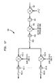
- FIG. 12 shows a downlink, i.e., base-to-subscriber, transmitter 120, suitable for use with the OFDM technique of FIG. 11 .
- the transmitter 120 includes an inverse DFT (IDFT) or inverse fast Fourier transform (IFFT) element 124, a parallel-to-serial converter 126, and multipliers 128, 130 and 132.
- IDFT inverse DFT
- IFFT inverse fast Fourier transform
- the M orthogonal frequency tones are applied to the IDFT or IFFT element 124.
- the first k of the M tones which are assigned to the uplink portion 104, contain no data, e.g., all zero levels.
- Tones k +1 to M which are assigned to the downlink portion 102, contain the downlink data, e.g., +1 and -1 levels.
- the element 124 generates the inverse transform of the M applied tones, and its output is supplied to the parallel-to-serial converter 126.
- the serial output of converter 126 is supplied to multiplier 128 in which the serial output is multiplied by a user-specific spreading code.
- the multiplier 128 is shown in a dashed box to indicate that it is an optional element. It presence will depend on whether the users in a beam are separated using codes, i.e., multiplier 128 will be present if the users in a beam are separated using codes.
- the output of the multiplier 128 is then multiplied by a sector-specific spreading code in multiplier 130, and the resulting signal is modulated onto a carrier corresponding to frequency ⁇ 0 in multiplier 132.
- the output of multiplier 132 is a downlink signal which is transmitted from the base station to a subscriber unit.
- FIG. 13 shows a corresponding downlink receiver 140 which may be implemented in the subscriber unit.
- the receiver 140 demodulates the received downlink signal using multiplier 142, and the demodulated signal is low-pass filtered using integrator 144.
- the filtered signal is de-spread by multiplying it by the sector-specific spreading code in multiplier 146, and summing in a sum element 148. If necessary, i.e., if the users in a beam are separated using codes, the output of sum element 148 is multiplied by the user-specific spreading code in multiplier 150 and then summed in a sum element 152. Otherwise, the elements 150, 152 may be eliminated and the output of sum element 148 is applied directly to a serial-to-parallel converter 154.
- the parallel outputs of the converter 154 are applied to a DFT or FFT element 156, which performs a DFT or FFT operation to recover the M tones.
- the first k tones, assigned to the uplink, do not include downlink data and are therefore discarded.
- the downlink data is present on tones k +1 to M.
- FIGS. 14 and 15 show an uplink, i.e., subscriber-to-base, transmitter and an uplink receiver, respectively, for implementing the OFDM technique of FIG. 11 .
- the uplink transmitter 220 of FIG. 14 includes an IDFT or IFFT element 224, a parallel-to-serial converter 226, an optional user-specific spreading code multiplier 228, a sector-specific spreading code multiplier 230, and a multiplier 232 for modulating the downlink signal onto a carrier.
- These elements operate in substantially the same manner as the corresponding elements of the downlink transmitter 120 of FIG. 12 , but the uplink data is applied to the first k tones, while tones k +1 through M contain no data.
- the output of multiplier 232 is an uplink signal which is transmitted from a subscriber unit to a base station.
- FIG. 15 shows the corresponding uplink receiver 240 which may be implemented in a base station.
- the receiver 240 includes a demodulating multiplier 242, an integrator 244, a sector-specific spreading code multiplier 246 and associated sum element 248, an optional user-specific spreading code multiplier 250 and its associated sum element 252, a serial-to-parallel converter 254, and a DFT or FFT element 256.
- These elements operate in substantially the same manner as the corresponding elements of the downlink receiver 140 of FIG. 13 , but the uplink data is present on the first k tones, while the tones k +1 through M do not include uplink data and are discarded.
- FIGS. 16 and 17 show a multi-code CDMA transmitter 300 and a multi-code CDMA receiver 400, respectively, in accordance with the invention.
- the transmitter 300 and receiver 400 are suitable for use with, e.g., the above-described CDD time-slotted CDMA and TDD time-slotted CDMA techniques.
- N spreading codes per beam in a given sector or cell of the system.
- the outputs of the multipliers 302- i are summed in element 304, and then multiplied by a sector-specific spreading code in multiplier 306.
- the output of multiplier 306 is modulated onto a carrier corresponding to frequency ⁇ 0 in multiplier 308.
- the resulting output signal may be transmitted from a base station to one or more subscriber units.
- the multi-code CDMA receiver 400 receives an input signal which is demodulated in multiplier 402, low-pass filtered in integrator 404, and then de-spread using the sector-specific spreading code in a multiplier 406 and associated sum element 408.
- the receiver 400 may be implemented in a base station to process signals received from multiple subscriber units of the system.
- a system in accordance with the invention may include additional elements, such as, for example, mobile switching centers (MSCs) for connecting one of more of the base stations to a public switched telephone network (PSTN), and a memory for storing, e.g., user data and billing information.
- MSCs mobile switching centers
- PSTN public switched telephone network
- transmitters and receivers shown herein for purposes of illustrating the invention may be implemented in many different ways, and may include a number of additional elements, e.g., diplexers, downconverters, upconverters, signal sources, filters, demodulators, modulators, baseband signal processors, etc., configured in a conventional manner.
- additional elements e.g., diplexers, downconverters, upconverters, signal sources, filters, demodulators, modulators, baseband signal processors, etc.
Description
- The present application is related to the following U.S. Patent Applications, both filed concurrently herewith in the name of inventor Syed Aon Mujtaba:
U.S. Patent Application Serial No. 09/200,523 entitled "Methods and Apparatus for Wireless Communication Using Orthogonal Frequency Division Multiplexing," which has since issued asU.S. Patent No. 7,020,071 , andU.S. Patent Application Serial No. 09/200,522 entitled "Methods and Apparatus for Wireless Communication Using Time Division Duplex Time-Slotted CDMA," which has since issued asU.S. Patent No. 6,542,485 . - The present invention relates generally to communication systems, and more particularly to wireless communication systems such as code division multiple access (CDMA) systems for fixed wireless loop (FWL) and other applications.
-
-
FIG. 1 shows a portion of a conventional omni-beam FWL system 10. The portion ofsystem 10 shown includes four hexagonal cells 12-1, 12-2, 12-3 and 12-4, each with a corresponding base station 14-1, 14-2, 14-3 and 14-4, and asubscriber unit 16. Thesystem 10 will generally include numerous additional cells, base stations and subscriber units configured in a similar manner. It is assumed in this system that the base stations are equipped with omni-directional antennas, and that the positions of the subscriber units are fixed. The base station 14-3 ofFIG. 1 is in communication with thesubscriber unit 16 in cell 12-3, e.g., for providing a communication channel for an on-going voice or data call. The omni-beam FWL system 10 may be configured using a number of different techniques. -
FIG. 2 shows an example of how the omni-beam FWL system 10 may be implemented using a time division multiple access (TDMA) technique such as that used in the Digital European Cordless Telephone (DECT) standard. In accordance with this TDMA technique, different frequencies are used for the different cells, such that among the cells, users are separated in frequency. A suitable frequency reuse pattern, e.g., a seven-cell hexagonal reuse pattern, may also be used in order to limit the number of different frequencies required. Within a given cell, users are separated in time through the use of a sequence oftime slots 20, including time slots 22-1, 22-2, ... 22-N. Thesystem 10 may also be implemented using a code division multiple access (CDMA) technique. In accordance with this technique, the same frequencies but different codes are used for each of the cells, such that the codes are used to separate users in different cells and within a given cell. Some frequency separation may also be used in conjunction with the code separation in order to reduce interference from other cells. Additional details regarding conventional CDMA systems are described in, for example, Andrew J. Viterbi, "CDMA: Principles of Spread Spectrum Communication," Addison-Wesley, 1995. Other conventional CDMA systems are described in, for example,
TIA/EIA/IS-95A, "Mobile Station - Base Station Compatibility Standard for Dual-Mode Wideband Spread Spectrum Cellular System," June 1996, and ANSI J-STD-008, "Personal Station - Base Station Compatibility Requirements for 1.8 to 2.0 GHz Code Division Multiple Access (CDMA) Personal Communication System". -
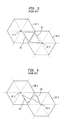
FIG. 3 shows a conventional narrow-beam FWL system 30. The portion ofsystem 30 shown includes four hexagonal cells 32-1, 32-2, 32-3 and 32-4, each with a corresponding base station 34-1, 34-2, 34-3 and 34-4. In this system, it is again assumed that the positions of the subscriber units are fixed. The base stations insystem 30 are equipped with directional antennas which generatenarrow beams 36. At any given time, only a subset of the total number of beams in the system is active, i.e., communicating with users. Thebeams 36 are made as narrow as possible in order to target only a single user, and thereby minimizing inter-cell interference. In order to provide an increased capacity, thesystem 30 may be configured such that all cells use the same frequencies, i.e., a frequency reuse factor of 1.FIG. 4 shows an alternative implementation in which a given cell 42-i includes nine electronically-steerablenarrow beams 46. Thebeams 46 are separated into three sectors, each including three beams designated 1, 2 and 3. This provides a more manageable hopping pattern, e.g., turning on a designated single beam within each sector at any given time. -
FIGS. 5 and 6 illustrate the difference between sectorization and steerable beams in a narrow-beam system such assystem 30 ofFIG. 3 , which assumes a frequency reuse factor of 1.FIG. 5 shows a pair of sectorized cells 50-1 and 50-2 having base stations 52-1 and 52-2, respectively. In this example, abeam 53 from one of six sectors of the cell 50-1 and abeam 55 from one of the six sectors of the cell 50-2 will generate co-channel, i.e., inter-cell, interference. If the beams are sectorized but not steerable, then it is generally not possible to mitigate this type of co-channel interference adaptively unless the sectors are separated in frequency.FIG. 6 shows an arrangement in which a pair of cells 60-1 and 60-2, via respective base stations 62-1 and 62-2, generate sectorized and steerable beams. It can be seen that, as illustrated by the relative positions ofsteerable beams -
FIG. 7 illustrates a conventional technique for separating uplink (UL) and downlink (DL) traffic for a given antenna beam in an omni-beam or narrow-beam system. In this technique, an uplink channel 72U and a downlink channel 72D are separated in frequency as shown, i.e., frequency division duplexing (FDD) is used to separate uplink and downlink traffic. Users of the uplink and downlink channels 72U and 72D are separated in time, using sequences of time slots 74-1, 74-2 74-3 ... and 76-1, 76-2, 76-3..., respectively. - The conventional techniques described above suffer from a number of disadvantages. For example, it is generally very difficult to generate narrow beams targeted to single users, as in the narrow-
beam FWL system 30 ofFIG. 3 . In addition, narrow beams of this type are susceptible to increased interference from effects such as shadowing and problematic sidelobes. Use of narrow beams in conjunction with a TDMA technique within a given cell can lead to catastrophic interference. For example, if beams from adjacent cells overlap, there is catastrophic interference since the signals are neither separated in frequency nor in time among the different cells, but are instead separated in the spatial domain. In a high density environment, this limitation can severely restrict capacity. Another problem is that conventional FDD techniques, such as those used to separate uplink and downlink inFIG. 7 , generally cannot adaptively tradeoff capacity between uplink and downlink. As a result, these FDD techniques are generally not well suited for use with, e.g., data-oriented wireless services. It is apparent from the foregoing that further improvements are needed in wireless communication techniques in order to overcome these and other problems of the prior art. - H. Asada et al., "A Study On Code Division Duplex (CDD) for Distributed CDMA Networks," Technical Report of the IEICE, March 1996, pp. 89-94, discloses conventional arrangements for separation of uplink and downlink communications using code division duplexing.
- A method and apparatus according to the present invention are set out in the independent claims, to which the reader is now referred. Preferred features are laid out in the dependent claims.
- The invention provides apparatus and methods for wireless communication in fixed wireless loop (FWL) and other types of systems in which, e.g., information is communicated in a given cell of the system between subscriber units and a base station over an uplink and a downlink. In accordance with a first aspect of the invention, a code division duplex (CDD) time-slotted CDMA wireless communication system is provided. Communications on the uplink are separated from communications on the downlink using code division duplexing, and communications with different subscriber units in the cell are separated using a code division multiple access technique, e.g., time-slotted CDMA. The code division duplexing may be implemented by, e.g., assigning a first subset of a set of codes to the uplink and a second subset of the set of codes to the downlink. The code assignment process may be repeated for different time slots, such that the number of codes in the first and second subsets varies across the time slots in accordance with uplink and downlink traffic demands. The system may utilize electronically-steered beams generated by antennas associated with the base stations. Any particular beam at a given time may have a width sufficient to provide simultaneous coverage for at least n of the subscriber units at that time, where n is greater than or equal to two. The n subscriber units are assigned different codes as part of the code division multiple access technique.
- The invention provides improved performance in wireless communication systems, particularly in applications involving heterogeneous traffic, e.g., mixed voice and data traffic, and other applications in which uplink and downlink capacity requirements are subject to large fluctuations. The invention is particularly well suited for use in applications such as omni-beam and narrow-beam FWL systems, although it can provide similar advantages in numerous other wireless communication applications.
-
-
FIG. 1 shows a portion of a conventional omni-beam FWL system -
FIG. 2 illustrates a conventional TDMA technique for use in the FWL system ofFIG. 1 . -
FIG. 3 shows a portion of a conventional narrow-beam FWL system. -
FIG. 4 illustrates an example of sectorization in a narrow-beam FWL system. -
FIGS. 5 and 6 illustrate distinctions between conventional sectorized and steerable beams. -
FIG. 7 illustrates a conventional technique which utilizes frequency division duplexing (FDD) to separate uplink and downlink and a TDMA technique to separate users. -
FIGS. 8 and 9 illustrate a code division duplex (FDD) time-slotted CDMA technique in accordance with the invention. -
FIG. 10 illustrates a time division duplex (TDD) time-slotted CDMA technique in accordance with an alternative proposal. - FfG. 11 illustrates an orthogonal frequency division multiplexing (OFDM) technique in accordance with an alternative proposal.
-
FIGS. 12 and13 show a downlink transmitter and a downlink receiver, respectively, for implementing the OFDM technique ofFIG. 11 -
FIGS. 14 and15 show an uplink transmitter and an uplink receiver, respectively, for implementing the OFDM technique ofFIG. 11 . -
FIGS. 16 and17 show a multi-code CDMA transmitter and a multi-code CDMA receiver, respectively, in accordance with the invention. - The present invention will be illustrated below in conjunction with exemplary wireless communication systems and communication techniques. It should be understood, however, that the invention is not limited to use with any particular type of communication system, but is instead more generally applicable to any wireless system in which it is desirable to provide improved performance without unduly increasing system complexity. For example, it will be apparent to those skilled in the art that the techniques are applicable to omni-beam and narrow-beam fixed wireless loop (FWL) systems, CDMA systems, as well as to other types of wideband and narrowband wireless systems. The term "subscriber unit" as used herein is intended to include fixed terminals such as fixed wireless installations, mobile terminals such as cellular telephones and portable computers, as well as other types of system terminals. The term "separating" as applied, e.g., to uplink and downlink or subscriber units in a given cell of a system refers generally to implementing the system such that interference between, e.g., the uplink and downlink or the subscriber units, is reduced, minimized, or eliminated.
- A number of communication techniques will be described for overcoming the above-noted problems of the prior art. The techniques differ in terms of the manner in which uplink and downlink portions of the system are separated, and/or the manner in which users are separated within a given cell. As noted previously, conventional techniques generally separate uplink and downlink portions of the system using frequency, e.g., FDD as shown in
FIG. 7 , and separate users within a given cell using, e.g., time slots as shown inFIG. 7 or codes. In a first technique in accordance with the invention, referred to herein as code division duplex (CDD) time-slotted CDMA, uplink and downlink portions of the system are separated using codes, while the users are also separated using codes. In a second technique in accordance with an alternate proposal referred to herein as time division duplex (TDD) time-slotted CDMA, uplink and downlink portions of the system are separated using time slots, while the users are separated using codes. In a third technique in accordance with an alternate proposal, referred to herein as orthogonal frequency division multiplexing (OFDM), uplink and downlink portions of the system are separated in frequency, while the users are also separated in frequency. Each of these techniques will be described in greater detail below. - An illustrative embodiment of the CDD time-slotted CDMA technique of the invention will be described with reference to
FIGS. 8 and 9. FIG. 8 shows a single cell 80-1 of a wireless system. The cell includes a base station 82-1 and a number ofsubscriber units 84. As shown, asingle antenna beam 86 generated by the base station 82-1 is directed to several subscriber units, i.e., five subscriber units in this example. Thebeam 86 is approximately 40° wide, such that there will be a total of nine beams generated in each cell. The additional beams are omitted fromFIG. 8 for clarity of illustration. It is also assumed that the beams in the cell 80-1 and the other cells of the corresponding system are electronically steerable. Thebeam 86 inFIG. 8 is purposely made wider than the typical single-user narrow beam in a conventional system such assystem 30 ofFIG. 3 , in order to target more than one subscriber unit. Although thebeam 86 is broader than, e.g., thebeam FIG. 6 , it can be configured to span a smaller portion of its sector. Within a given cell, such as cell 80-1, users are separated by codes, i.e., assigned different codes to prevent the users in thebeam 86 from interfering with one another. Among adjacent cells, users are also separated by codes. Thus, when beams from adjacent cells collide, the interference will not be catastrophic since the users in adjacent cells are separated by codes. Standard CDMA techniques, such as those described in the above-cited CDMA references, may be used to separate the users within a cell and among adjacent cells. The technique is "time-slotted" in that the beams are steerable, such that different beams can be activated in different time slots, and may also be referred to as "discontinuous-transmission" CDMA. -
FIG. 9 shows an exemplary CDD mechanism suitable for use in the CDD time-slotted CDMA technique of the invention. In this embodiment, the CDD mechanism is implemented by using different codes for the uplink and downlink portions of the system. For example, as shown, the uplink uses code N, code N-1, etc., whilecode 1,code 2, etc., are used for the downlink. Theboundary 90 between the uplink codes and the downlink codes is variable, such that the capacity allocated to uplink and downlink can be adaptively altered to account for demand variations. For example, theboundary 90 can vary for each time slot, or for each group of a predetermined number of time slots. - The CDD time-slotted CDMA technique described above provides a number of advantages over conventional,techniques. For example, a system implemented using such a technique does not require an unduly narrow beam designed to target a single subscriber unit. In addition, uplink and downlink can be traded off by reassignment of uplink and downlink codes, and an efficient closed loop power control process can be maintained since both the uplink and downlink can be on the same frequency. A fixed quality of service (QoS) can be provided for a given user by utilizing the same uplink-downlink code boundary for each slot assigned to that user. Moreover, the variable boundary makes it easier to accommodate variable rate users, e.g., through multicode or variable rate spreading, and to transmit heterogeneous traffic, e.g., voice and data traffic.
-
FIG. 10 illustrates a TDD time-slotted CDMA technique in accordance with an alternate proposal. This technique is the same as the CDD time-slotted CDMA technique described in conjunction withFIGS. 8 and 9 , except that a different duplexing mechanism, i.e., a time division rather than code division technique, is used to separate the uplink and downlink portions of the system.FIG. 10 illustrates the duplexing used in the TDD time-slotted CDMA technique. One or more of the time slots are assigned to the downlink, while others are assigned to the uplink. The assignment of time slots to uplink or downlink may be varied adaptively, so as to accommodate variations in uplink and downlink traffic demands. The other aspects of the system are otherwise the same as in the CDD time-slotted CDMA technique, i.e., beams of the type described inFIG. 8 may be used, and users are separated within a given cell and among adjacent cells through the use of codes. -
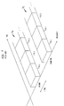
FIG. 11 illustrates an OFDM technique in accordance with an alternate proposal. In this technique, duplexing between the uplink and downlink portions is performed adaptively in the frequency domain, using orthogonal frequency tones, rather than the conventional FDD as described in conjunction withFIG. 7 . This technique allows for asymmetric uplink and downlink capacity. As shown inFIG. 11 , adownlink portion 102 and anuplink portion 104 are separated in frequency by avariable boundary 106. There are a total of M orthogonal frequency tones 110 in the band of interest. In theFIG. 11 example, tones 1 through k are assigned to theuplink portion 104, while tones k+I to M are assigned to thedownlink portion 102. Unlike the conventional FDD technique, this OFDM technique allows frequencies to be assigned adaptively between uplink and downlink in order to accommodate variations in demand. Within a given cell, uplink and downlink portions may be separated, e.g., in the discrete Fourier transform (DFT) domain based on assignment of OFDM carriers. Users within a given beam can be separated, e.g., by using different time slots or different codes, or other suitable techniques. Users separation among different beams of a given cell may be implemented using different codes. Among adjacent cells, frequencies or codes may be used to separate the various users. - In the OFDM technique of
FIG. 11 , appropriate timing synchronization is generally required between the base station and the subscriber unit in order to maintain tone orthogonality. This timing synchronization can be easily achieved through a "sync" control channel transmitted by the base station to the subscriber unit. Frequency synchronization is also generally required between the base station and the subscriber unit. Since the subscriber unit in the illustrative embodiment is fixed, there is no frequency offset due to Doppler effects. Hence, frequency synchronization in such a system can be implemented in a straightforward manner. Accurate power control is also generally required between the base station and the subscriber unit. Again, since the subscriber unit is fixed, the time variation of the wireless channel is very slow, which allows for straightforward implementation of accurate power control. -
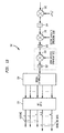
FIG. 12 shows a downlink, i.e., base-to-subscriber,transmitter 120, suitable for use with the OFDM technique ofFIG. 11 . Thetransmitter 120 includes an inverse DFT (IDFT) or inverse fast Fourier transform (IFFT)element 124, a parallel-to-serial converter 126, andmultipliers IFFT element 124. The first k of the M tones, which are assigned to theuplink portion 104, contain no data, e.g., all zero levels. Tones k+1 to M, which are assigned to thedownlink portion 102, contain the downlink data, e.g., +1 and -1 levels. Theelement 124 generates the inverse transform of the M applied tones, and its output is supplied to the parallel-to-serial converter 126. The serial output ofconverter 126 is supplied tomultiplier 128 in which the serial output is multiplied by a user-specific spreading code. Themultiplier 128 is shown in a dashed box to indicate that it is an optional element. It presence will depend on whether the users in a beam are separated using codes, i.e.,multiplier 128 will be present if the users in a beam are separated using codes. The output of themultiplier 128 is then multiplied by a sector-specific spreading code inmultiplier 130, and the resulting signal is modulated onto a carrier corresponding to frequency ω0 inmultiplier 132. The output ofmultiplier 132 is a downlink signal which is transmitted from the base station to a subscriber unit. -
FIG. 13 shows acorresponding downlink receiver 140 which may be implemented in the subscriber unit. Thereceiver 140 demodulates the received downlinksignal using multiplier 142, and the demodulated signal is low-pass filtered usingintegrator 144. The filtered signal is de-spread by multiplying it by the sector-specific spreading code inmultiplier 146, and summing in asum element 148. If necessary, i.e., if the users in a beam are separated using codes, the output ofsum element 148 is multiplied by the user-specific spreading code inmultiplier 150 and then summed in asum element 152. Otherwise, theelements sum element 148 is applied directly to a serial-to-parallel converter 154. The parallel outputs of theconverter 154 are applied to a DFT orFFT element 156, which performs a DFT or FFT operation to recover the M tones. The first k tones, assigned to the uplink, do not include downlink data and are therefore discarded. The downlink data is present on tones k+1 to M. -
FIGS. 14 and15 show an uplink, i.e., subscriber-to-base, transmitter and an uplink receiver, respectively, for implementing the OFDM technique ofFIG. 11 . Theuplink transmitter 220 ofFIG. 14 includes an IDFT orIFFT element 224, a parallel-to-serial converter 226, an optional user-specific spreadingcode multiplier 228, a sector-specific spreadingcode multiplier 230, and amultiplier 232 for modulating the downlink signal onto a carrier. These elements operate in substantially the same manner as the corresponding elements of thedownlink transmitter 120 ofFIG. 12 , but the uplink data is applied to the first k tones, while tones k+1 through M contain no data. The output ofmultiplier 232 is an uplink signal which is transmitted from a subscriber unit to a base station.FIG. 15 shows the correspondinguplink receiver 240 which may be implemented in a base station. Thereceiver 240 includes ademodulating multiplier 242, anintegrator 244, a sector-specific spreadingcode multiplier 246 andassociated sum element 248, an optional user-specific spreadingcode multiplier 250 and itsassociated sum element 252, a serial-to-parallel converter 254, and a DFT orFFT element 256. These elements operate in substantially the same manner as the corresponding elements of thedownlink receiver 140 ofFIG. 13 , but the uplink data is present on the first k tones, while the tones k+1 through M do not include uplink data and are discarded. -
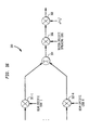
FIGS. 16 and17 show amulti-code CDMA transmitter 300 and amulti-code CDMA receiver 400, respectively, in accordance with the invention. Thetransmitter 300 andreceiver 400 are suitable for use with, e.g., the above-described CDD time-slotted CDMA and TDD time-slotted CDMA techniques. In thetransmitter 300 andreceiver 400, it is assumed that there are a total of N spreading codes per beam in a given sector or cell of the system. Thetransmitter 300 receives N input signals in corresponding beam-specific code multipliers 302-i, i = 1, 2, ... N. The outputs of the multipliers 302-i are summed inelement 304, and then multiplied by a sector-specific spreading code inmultiplier 306. The output ofmultiplier 306 is modulated onto a carrier corresponding to frequency ω0 inmultiplier 308. The resulting output signal may be transmitted from a base station to one or more subscriber units. - The
multi-code CDMA receiver 400 receives an input signal which is demodulated inmultiplier 402, low-pass filtered inintegrator 404, and then de-spread using the sector-specific spreading code in amultiplier 406 andassociated sum element 408. Asampling switch 410 is controlled so as to "dump" samples every symbol time. The samples are de-spread in multipliers 412-i, i = 1, 2, ... N, and associated sum elements 414-i, using corresponding beam-specific codes. Sampling switches 416-i deliver a separate output for each of the beam-specific codes. Thereceiver 400 may be implemented in a base station to process signals received from multiple subscriber units of the system. - It should be emphasized that the exemplary wireless systems and devices described herein are intended to illustrate the operation of the invention, and therefore should not be construed as limiting the invention to any particular embodiment or group of embodiments. For example, although well suited for implementation in an omni-beam or narrow-beam FWL system, the invention can be used in other applications. In addition, a system in accordance with the invention may include additional elements, such as, for example, mobile switching centers (MSCs) for connecting one of more of the base stations to a public switched telephone network (PSTN), and a memory for storing, e.g., user data and billing information. Furthermore, it will be apparent to those skilled in the art that the transmitters and receivers shown herein for purposes of illustrating the invention may be implemented in many different ways, and may include a number of additional elements, e.g., diplexers, downconverters, upconverters, signal sources, filters, demodulators, modulators, baseband signal processors, etc., configured in a conventional manner. These and numerous other alternative embodiments within the scope of the following claims will therefore be apparent to those skilled in the art.
Claims (9)
- A method of communicating information between a base station and a plurality of subscriber units, the method comprising the steps of:separating a plurality of code division duplex codes into first and second subsets;assigning the first subset of the plurality of code division duplex codes to an uplink between the subscriber units and the base station and the second subset of the plurality of code division duplex codes to a downlink between the base station and the subscriber units;receiving communications in the base station from one or more of the subscriber units using the assigned first subset of code division duplex codes;transmitting communications from the base station to one or more of the subscriber units using the assigned second subset of code division duplex codes; and characterized byrepeating the separating, assigning, receiving and transmitting steps for subsequent communications using a different separation of the code division duplex codes into the first and second subsets of codes.
- The method of claim 1 wherein the base station and the plurality of subscriber units are elements of a fixed wireless loop system.
- The method of claim 1 wherein the plurality of code division duplex codes comprises a total of N codes separated into the first and second subsets, and further wherein a different separation of the N codes into the first and second subsets is used for each of a plurality of different sets of the subsequent communications.
- An apparatus for use in a communication system, the apparatus comprising:a base station operative to communicate with a plurality of subscriber units;wherein the base station is configured to separate a plurality of code division duplex codes into first and second subsets, and to assign the first subset of the plurality of code division duplex codes to an uplink between the subscriber units and the base station and the second subset of the plurality of code division duplex codes to a downlink between the base station and the subscriber units;to receive communications from one or more of the subscriber units using the assigned first subset of code division duplex codes;to transmit communications to one or more of the subscriber units using the assigned second subset of code division duplex codes; and characterized in thatthe base station is further configured to repeat the separating, assigning, receiving and transmitting operations for subsequent communications using a different separation of the code division duplex codes into the first and second subsets of codes.
- The apparatus of claim 4 wherein the base station is a base station of a fixed wireless loop system.
- The apparatus of claim 4 wherein the plurality of code division duplex codes comprises a total of N codes separated into the first and second subsets, and further wherein a different separation of the N codes into the first and second subsets is used for each of a plurality of different sets of the subsequent communications.
- A communication system comprising:a plurality of subscriber units; anda base station operative to communicate with the plurality of subscriber units;wherein the base station is configured to separate a plurality of code division duplex codes into first and second subsets, and to assign the first subset of the plurality of code division duplex codes to an uplink between the subscriber units and the base station and the second subset of the plurality of code division duplex codes to a downlink between the base station and the subscriber units;to receive communications from one or more of the subscriber units using the assigned first subset of code division duplex codes;to transmit communications to one or more of the subscriber units using the assigned second subset of code division duplex codes; and characterized in thatthe base station is further configured to repeat the separating, assigning, receiving and transmitting operations for subsequent communications using a different separation of the code division duplex codes into the first and second subsets of codes.
- The system of claim 7 wherein the system is a fixed wireless loop system.
- The system of claim 7 wherein the plurality of code division duplex codes comprises a total of N codes separated into the first and second subsets, and further wherein a different separation of the N codes into the first and second subsets is used for each of a plurality of different sets of the subsequent communications.
Applications Claiming Priority (2)
| Application Number | Priority Date | Filing Date | Title |
|---|---|---|---|
| US09/200,521 US6813254B1 (en) | 1998-11-25 | 1998-11-25 | Methods and apparatus for wireless communication using code division duplex time-slotted CDMA |
| US200521 | 1998-11-25 |
Publications (3)
| Publication Number | Publication Date |
|---|---|
| EP1005180A2 EP1005180A2 (en) | 2000-05-31 |
| EP1005180A3 EP1005180A3 (en) | 2006-03-15 |
| EP1005180B1 true EP1005180B1 (en) | 2011-02-09 |
Family
ID=22742063
Family Applications (1)
| Application Number | Title | Priority Date | Filing Date |
|---|---|---|---|
| EP99309123A Expired - Lifetime EP1005180B1 (en) | 1998-11-25 | 1999-11-16 | Methods and apparatus for wireless communication using code division duplex time-slotted cdma |
Country Status (5)
| Country | Link |
|---|---|
| US (1) | US6813254B1 (en) |
| EP (1) | EP1005180B1 (en) |
| JP (2) | JP2000165940A (en) |
| CA (1) | CA2286417C (en) |
| DE (1) | DE69943180D1 (en) |
Families Citing this family (13)
| Publication number | Priority date | Publication date | Assignee | Title |
|---|---|---|---|---|
| FI104135B (en) * | 1997-06-24 | 1999-11-15 | Nokia Mobile Phones Ltd | Time division multiple access radio systems |
| EP1089512A1 (en) * | 1999-09-30 | 2001-04-04 | Sony International (Europe) GmbH | Telecommunication device with analog fourier transformation unit |
| US7227850B2 (en) * | 2001-04-04 | 2007-06-05 | Telefonaktiebolaget Lm Ericsson (Publ) | Cellular radio communication system with frequency reuse |
| US20040004951A1 (en) | 2002-07-05 | 2004-01-08 | Interdigital Technology Corporation | Method for performing wireless switching |
| KR100474849B1 (en) * | 2002-11-01 | 2005-03-11 | 삼성전자주식회사 | Code reuse method and apparatus in CDMA wireless communication system using beam forming by array antenna |
| US7493133B2 (en) * | 2004-02-05 | 2009-02-17 | Qualcomm, Incorporated | Power control in ad-hoc wireless networks |
| US20060289439A1 (en) * | 2005-03-21 | 2006-12-28 | Samantha Dreimann | Food steamer with plurality of compartments |
| US7957327B2 (en) * | 2005-05-18 | 2011-06-07 | Qualcomm Incorporated | Efficient support for TDD beamforming via constrained hopping and on-demand pilot |
| JP2008017341A (en) * | 2006-07-07 | 2008-01-24 | Ntt Docomo Inc | Radio communication apparatus and method |
| CN100594689C (en) * | 2006-09-20 | 2010-03-17 | 北京大学 | A code division duplex communication method |
| US9681455B2 (en) * | 2010-01-28 | 2017-06-13 | Alcatel Lucent | Methods for reducing interference in a communication system |
| US9086472B2 (en) * | 2012-09-26 | 2015-07-21 | Gennadii Ivtsenkov | Multi-transceiver RF alert system for preventing hunting accidents |
| KR101817014B1 (en) * | 2015-09-18 | 2018-01-10 | 한국과학기술원 | Method for multi-beam code division multiple access communication, and an apparatus performing the same |
Family Cites Families (27)
| Publication number | Priority date | Publication date | Assignee | Title |
|---|---|---|---|---|
| US5627880A (en) * | 1992-11-02 | 1997-05-06 | Motorola, Inc. | MAHO method for SFH-CDMA/TDMA using punctured frames |
| SE9203384L (en) | 1992-11-13 | 1993-10-25 | Televerket | Method and apparatus for dynamic allocation of multiple carrier channels for multiple access through frequency multiplexing |
| US5420851A (en) * | 1993-11-24 | 1995-05-30 | At&T Corp. | Method of multiple access |
| DE69434353T2 (en) | 1993-12-22 | 2006-03-09 | Koninklijke Philips Electronics N.V. | Multi-carrier frequency hopping communication system |
| JPH07226978A (en) * | 1994-02-14 | 1995-08-22 | Matsushita Electric Ind Co Ltd | Multiplex communication equipment |
| EP0696398A1 (en) | 1994-02-25 | 1996-02-14 | Koninklijke Philips Electronics N.V. | A multiple access digital transmission system and a radio base station and a receiver for use in such a system |
| US6018528A (en) * | 1994-04-28 | 2000-01-25 | At&T Corp | System and method for optimizing spectral efficiency using time-frequency-code slicing |
| US5596333A (en) * | 1994-08-31 | 1997-01-21 | Motorola, Inc. | Method and apparatus for conveying a communication signal between a communication unit and a base site |
| US5614914A (en) | 1994-09-06 | 1997-03-25 | Interdigital Technology Corporation | Wireless telephone distribution system with time and space diversity transmission for determining receiver location |
| JP3480761B2 (en) * | 1995-03-30 | 2003-12-22 | 株式会社東芝 | Wireless communication method |
| US6049535A (en) * | 1996-06-27 | 2000-04-11 | Interdigital Technology Corporation | Code division multiple access (CDMA) communication system |
| GB2307621B (en) * | 1995-11-21 | 1997-12-03 | At & T Corp | Cdma air interface for radio local loop system |
| CA2216761C (en) * | 1996-11-08 | 2002-01-01 | Lucent Technologies Inc. | Tdm-based fixed wireless loop system |
| JPH10190616A (en) * | 1996-12-20 | 1998-07-21 | Oki Electric Ind Co Ltd | Hand-over controller |
| DE69731978T2 (en) * | 1997-02-13 | 2005-10-06 | Nokia Corp. | METHOD AND DEVICE FOR TRANSMITTED RADIO TRANSMISSION |
| US6122266A (en) * | 1997-02-19 | 2000-09-19 | Lucent Technologies Inc. | Multi-level sectorized CDMA communications |
| JP3392704B2 (en) * | 1997-05-09 | 2003-03-31 | 株式会社東芝 | Wireless communication system and wireless base station |
| US6005854A (en) * | 1997-08-08 | 1999-12-21 | Cwill Telecommunication, Inc. | Synchronous wireless access protocol method and apparatus |
| US6282179B1 (en) * | 1997-10-17 | 2001-08-28 | At&T Corp. | Method and system for reducing multipath fading in bent-pipe satellite communications systems |
| US6118767A (en) * | 1997-11-19 | 2000-09-12 | Metawave Communications Corporation | Interference control for CDMA networks using a plurality of narrow antenna beams and an estimation of the number of users/remote signals present |
| US6067315A (en) * | 1997-12-04 | 2000-05-23 | Telefonaktiebolaget Lm Ericsson | Method and apparatus for coherently-averaged power estimation |
| US6208871B1 (en) * | 1998-02-27 | 2001-03-27 | Motorola, Inc. | Method and apparatus for providing a time adjustment to a wireless communication system |
| US6178333B1 (en) * | 1998-04-15 | 2001-01-23 | Metawave Communications Corporation | System and method providing delays for CDMA nulling |
| US6181276B1 (en) * | 1998-10-09 | 2001-01-30 | Metawave Communications Corporation | Sector shaping transition system and method |
| US6542485B1 (en) * | 1998-11-25 | 2003-04-01 | Lucent Technologies Inc. | Methods and apparatus for wireless communication using time division duplex time-slotted CDMA |
| US6091757A (en) * | 1998-12-03 | 2000-07-18 | Motorola, Inc. | Data transmission within a spread-spectrum communication system |
| AU2001238646A1 (en) * | 2000-02-24 | 2001-09-03 | Tantivy Communications, Inc. | Method and system for economical beam forming in a radio communication system |
-
1998
- 1998-11-25 US US09/200,521 patent/US6813254B1/en not_active Expired - Lifetime
-
1999
- 1999-10-18 CA CA002286417A patent/CA2286417C/en not_active Expired - Lifetime
- 1999-11-16 EP EP99309123A patent/EP1005180B1/en not_active Expired - Lifetime
- 1999-11-16 DE DE69943180T patent/DE69943180D1/en not_active Expired - Lifetime
- 1999-11-24 JP JP11333385A patent/JP2000165940A/en active Pending
-
2009
- 2009-01-22 JP JP2009011705A patent/JP4598132B2/en not_active Expired - Fee Related
Also Published As
| Publication number | Publication date |
|---|---|
| JP4598132B2 (en) | 2010-12-15 |
| CA2286417A1 (en) | 2000-05-25 |
| EP1005180A2 (en) | 2000-05-31 |
| EP1005180A3 (en) | 2006-03-15 |
| DE69943180D1 (en) | 2011-03-24 |
| US6813254B1 (en) | 2004-11-02 |
| CA2286417C (en) | 2006-01-03 |
| JP2000165940A (en) | 2000-06-16 |
| JP2009135953A (en) | 2009-06-18 |
Similar Documents
| Publication | Publication Date | Title |
|---|---|---|
| CA2287022C (en) | Methods and apparatus for wireless communication using orthogonal frequency division multiplexing | |
| CA2287004C (en) | Method and apparatus for wireless communication using time division duplex time-slotted cdma | |
| JP4598132B2 (en) | Method for communicating information in a wireless cellular communication system | |
| JP2992670B2 (en) | Mobile communication device | |
| KR100883942B1 (en) | Multiplexing of real time services and non-real time services for ofdm systems | |
| US6600776B1 (en) | Vertical adaptive antenna array for a discrete multitone spread spectrum communications system | |
| US6782039B2 (en) | Vertical adaptive antenna array for a discrete multitone spread spectrum communications system | |
| US6621851B1 (en) | Priority messaging method for a discrete multitone spread spectrum communications system | |
| KR100983687B1 (en) | Allocation of tones in a multicarrier communication system | |
| EP1908200B1 (en) | Sdma for wcdma with increased capacity by use of multiple scrambling codes | |
| US6160839A (en) | Adaptive weight update method for a discrete multitone spread spectrum communications system | |
| EP1687914B1 (en) | Method for partitioning resource space, assigning physical channel, and allocating power in ofdma-based cellular system | |
| EP1043861A1 (en) | Frequency hopping multicarrier transmission in segmented cells | |
| US20050237989A1 (en) | Method of allocating subcarriers in orthogonal frequency division multiplexing (OFDM) cellular system | |
| JP2006522503A (en) | Subcarrier allocation method for reducing inter-cell interference in an OFDM cellular environment | |
| WO2001069826A1 (en) | Radio communication apparatus and radio communication method | |
| US8116691B2 (en) | Systems and methods for improving reference signals for spatially multiplexed cellular systems | |
| US20080232486A1 (en) | Systems and methods for extending zadoff-chu sequences to a non-prime number length to minimize average correlation | |
| EP0966797B1 (en) | Highly bandwidth-efficient communications | |
| US7961587B2 (en) | Systems and methods for reducing peak to average cross-correlation for sequences designed by alternating projections | |
| Lee | CS-OFDMA: A new wireless CDD physical layer scheme | |
| Fazel et al. | A Digital Microwave Point-to-Multi-Point (PMP) System Based on Multi-Carrier FDMA Transmission |
Legal Events
| Date | Code | Title | Description |
|---|---|---|---|
| PUAI | Public reference made under article 153(3) epc to a published international application that has entered the european phase |
Free format text: ORIGINAL CODE: 0009012 |
|
| AK | Designated contracting states |
Kind code of ref document: A2 Designated state(s): AT BE CH CY DE DK ES FI FR GB GR IE IT LI LU MC NL PT SE |
|
| AX | Request for extension of the european patent |
Free format text: AL;LT;LV;MK;RO;SI |
|
| PUAL | Search report despatched |
Free format text: ORIGINAL CODE: 0009013 |
|
| AK | Designated contracting states |
Kind code of ref document: A3 Designated state(s): AT BE CH CY DE DK ES FI FR GB GR IE IT LI LU MC NL PT SE |
|
| AX | Request for extension of the european patent |
Extension state: AL LT LV MK RO SI |
|
| AKX | Designation fees paid |
Designated state(s): DE FR GB |
|
| 17P | Request for examination filed |
Effective date: 20060901 |
|
| 17Q | First examination report despatched |
Effective date: 20070829 |
|
| RAP3 | Party data changed (applicant data changed or rights of an application transferred) |
Owner name: LUCENT TECHNOLOGIES INC. |
|
| GRAP | Despatch of communication of intention to grant a patent |
Free format text: ORIGINAL CODE: EPIDOSNIGR1 |
|
| RAP1 | Party data changed (applicant data changed or rights of an application transferred) |
Owner name: ALCATEL-LUCENT USA INC. |
|
| GRAS | Grant fee paid |
Free format text: ORIGINAL CODE: EPIDOSNIGR3 |
|
| GRAA | (expected) grant |
Free format text: ORIGINAL CODE: 0009210 |
|
| AK | Designated contracting states |
Kind code of ref document: B1 Designated state(s): DE FR GB |
|
| REG | Reference to a national code |
Ref country code: GB Ref legal event code: FG4D |
|
| REF | Corresponds to: |
Ref document number: 69943180 Country of ref document: DE Date of ref document: 20110324 Kind code of ref document: P |
|
| REG | Reference to a national code |
Ref country code: DE Ref legal event code: R096 Ref document number: 69943180 Country of ref document: DE Effective date: 20110324 |
|
| PLBE | No opposition filed within time limit |
Free format text: ORIGINAL CODE: 0009261 |
|
| STAA | Information on the status of an ep patent application or granted ep patent |
Free format text: STATUS: NO OPPOSITION FILED WITHIN TIME LIMIT |
|
| 26N | No opposition filed |
Effective date: 20111110 |
|
| REG | Reference to a national code |
Ref country code: DE Ref legal event code: R097 Ref document number: 69943180 Country of ref document: DE Effective date: 20111110 |
|
| REG | Reference to a national code |
Ref country code: GB Ref legal event code: 732E Free format text: REGISTERED BETWEEN 20131024 AND 20131030 |
|
| REG | Reference to a national code |
Ref country code: FR Ref legal event code: GC Effective date: 20140715 |
|
| REG | Reference to a national code |
Ref country code: FR Ref legal event code: RG Effective date: 20141015 |
|
| REG | Reference to a national code |
Ref country code: FR Ref legal event code: PLFP Year of fee payment: 17 |
|
| REG | Reference to a national code |
Ref country code: FR Ref legal event code: PLFP Year of fee payment: 18 |
|
| REG | Reference to a national code |
Ref country code: FR Ref legal event code: PLFP Year of fee payment: 19 |
|
| PGFP | Annual fee paid to national office [announced via postgrant information from national office to epo] |
Ref country code: DE Payment date: 20171121 Year of fee payment: 19 |
|
| PGFP | Annual fee paid to national office [announced via postgrant information from national office to epo] |
Ref country code: GB Payment date: 20171123 Year of fee payment: 19 |
|
| REG | Reference to a national code |
Ref country code: FR Ref legal event code: PLFP Year of fee payment: 20 |
|
| PGFP | Annual fee paid to national office [announced via postgrant information from national office to epo] |
Ref country code: FR Payment date: 20181011 Year of fee payment: 20 |
|
| REG | Reference to a national code |
Ref country code: DE Ref legal event code: R119 Ref document number: 69943180 Country of ref document: DE |
|
| GBPC | Gb: european patent ceased through non-payment of renewal fee |
Effective date: 20181116 |
|
| PG25 | Lapsed in a contracting state [announced via postgrant information from national office to epo] |
Ref country code: DE Free format text: LAPSE BECAUSE OF NON-PAYMENT OF DUE FEES Effective date: 20190601 |
|
| PG25 | Lapsed in a contracting state [announced via postgrant information from national office to epo] |
Ref country code: GB Free format text: LAPSE BECAUSE OF NON-PAYMENT OF DUE FEES Effective date: 20181116 |