EP1005059A1 - Thermal switch - Google Patents
Thermal switch Download PDFInfo
- Publication number
- EP1005059A1 EP1005059A1 EP99630090A EP99630090A EP1005059A1 EP 1005059 A1 EP1005059 A1 EP 1005059A1 EP 99630090 A EP99630090 A EP 99630090A EP 99630090 A EP99630090 A EP 99630090A EP 1005059 A1 EP1005059 A1 EP 1005059A1
- Authority
- EP
- European Patent Office
- Prior art keywords
- actuator
- blade
- actuator member
- base
- peripheral wall
- Prior art date
- Legal status (The legal status is an assumption and is not a legal conclusion. Google has not performed a legal analysis and makes no representation as to the accuracy of the status listed.)
- Withdrawn
Links
- 230000002093 peripheral effect Effects 0.000 claims abstract description 60
- 239000003351 stiffener Substances 0.000 claims abstract description 57
- 239000012212 insulator Substances 0.000 claims abstract description 22
- 229910052751 metal Inorganic materials 0.000 claims abstract description 22
- 239000002184 metal Substances 0.000 claims abstract description 22
- 239000004033 plastic Substances 0.000 claims abstract description 17
- 239000010970 precious metal Substances 0.000 claims description 14
- 239000011888 foil Substances 0.000 claims description 11
- 239000000615 nonconductor Substances 0.000 claims 2
- 229910001285 shape-memory alloy Inorganic materials 0.000 claims 1
- 230000007704 transition Effects 0.000 abstract description 4
- PXHVJJICTQNCMI-UHFFFAOYSA-N Nickel Chemical compound [Ni] PXHVJJICTQNCMI-UHFFFAOYSA-N 0.000 description 6
- 229910001566 austenite Inorganic materials 0.000 description 6
- 230000009466 transformation Effects 0.000 description 5
- 238000005452 bending Methods 0.000 description 4
- 230000006835 compression Effects 0.000 description 4
- 238000007906 compression Methods 0.000 description 4
- 238000001816 cooling Methods 0.000 description 3
- 230000006870 function Effects 0.000 description 3
- 239000000463 material Substances 0.000 description 3
- BQCADISMDOOEFD-UHFFFAOYSA-N Silver Chemical compound [Ag] BQCADISMDOOEFD-UHFFFAOYSA-N 0.000 description 2
- 230000004075 alteration Effects 0.000 description 2
- 229910052782 aluminium Inorganic materials 0.000 description 2
- XAGFODPZIPBFFR-UHFFFAOYSA-N aluminium Chemical compound [Al] XAGFODPZIPBFFR-UHFFFAOYSA-N 0.000 description 2
- 239000011324 bead Substances 0.000 description 2
- 238000002788 crimping Methods 0.000 description 2
- 238000010438 heat treatment Methods 0.000 description 2
- 238000012986 modification Methods 0.000 description 2
- 230000004048 modification Effects 0.000 description 2
- 229910052759 nickel Inorganic materials 0.000 description 2
- 238000013021 overheating Methods 0.000 description 2
- 238000007747 plating Methods 0.000 description 2
- 229910052709 silver Inorganic materials 0.000 description 2
- 239000004332 silver Substances 0.000 description 2
- 238000003466 welding Methods 0.000 description 2
- RYGMFSIKBFXOCR-UHFFFAOYSA-N Copper Chemical compound [Cu] RYGMFSIKBFXOCR-UHFFFAOYSA-N 0.000 description 1
- 239000004952 Polyamide Substances 0.000 description 1
- 239000004743 Polypropylene Substances 0.000 description 1
- HZEWFHLRYVTOIW-UHFFFAOYSA-N [Ti].[Ni] Chemical compound [Ti].[Ni] HZEWFHLRYVTOIW-UHFFFAOYSA-N 0.000 description 1
- 230000008859 change Effects 0.000 description 1
- 239000011248 coating agent Substances 0.000 description 1
- 238000000576 coating method Methods 0.000 description 1
- 239000010960 cold rolled steel Substances 0.000 description 1
- 229910052802 copper Inorganic materials 0.000 description 1
- 239000010949 copper Substances 0.000 description 1
- 230000000994 depressogenic effect Effects 0.000 description 1
- 238000006073 displacement reaction Methods 0.000 description 1
- PCHJSUWPFVWCPO-UHFFFAOYSA-N gold Chemical compound [Au] PCHJSUWPFVWCPO-UHFFFAOYSA-N 0.000 description 1
- 229910052737 gold Inorganic materials 0.000 description 1
- 239000010931 gold Substances 0.000 description 1
- 238000003780 insertion Methods 0.000 description 1
- 230000037431 insertion Effects 0.000 description 1
- 239000011810 insulating material Substances 0.000 description 1
- 230000002452 interceptive effect Effects 0.000 description 1
- 229910000734 martensite Inorganic materials 0.000 description 1
- 150000002739 metals Chemical class 0.000 description 1
- 229910001000 nickel titanium Inorganic materials 0.000 description 1
- 229920002647 polyamide Polymers 0.000 description 1
- -1 polypropylene Polymers 0.000 description 1
- 229920001155 polypropylene Polymers 0.000 description 1
- 230000001681 protective effect Effects 0.000 description 1
- 230000005855 radiation Effects 0.000 description 1
- 230000009467 reduction Effects 0.000 description 1
- 239000012781 shape memory material Substances 0.000 description 1
- 238000004544 sputter deposition Methods 0.000 description 1
- 238000007740 vapor deposition Methods 0.000 description 1
Images


Classifications
-
- H—ELECTRICITY
- H01—ELECTRIC ELEMENTS
- H01H—ELECTRIC SWITCHES; RELAYS; SELECTORS; EMERGENCY PROTECTIVE DEVICES
- H01H37/00—Thermally-actuated switches
-
- H—ELECTRICITY
- H01—ELECTRIC ELEMENTS
- H01H—ELECTRIC SWITCHES; RELAYS; SELECTORS; EMERGENCY PROTECTIVE DEVICES
- H01H37/00—Thermally-actuated switches
- H01H37/02—Details
- H01H37/32—Thermally-sensitive members
- H01H37/323—Thermally-sensitive members making use of shape memory materials
-
- H—ELECTRICITY
- H01—ELECTRIC ELEMENTS
- H01M—PROCESSES OR MEANS, e.g. BATTERIES, FOR THE DIRECT CONVERSION OF CHEMICAL ENERGY INTO ELECTRICAL ENERGY
- H01M50/00—Constructional details or processes of manufacture of the non-active parts of electrochemical cells other than fuel cells, e.g. hybrid cells
- H01M50/50—Current conducting connections for cells or batteries
- H01M50/572—Means for preventing undesired use or discharge
- H01M50/574—Devices or arrangements for the interruption of current
- H01M50/581—Devices or arrangements for the interruption of current in response to temperature
-
- H—ELECTRICITY
- H01—ELECTRIC ELEMENTS
- H01M—PROCESSES OR MEANS, e.g. BATTERIES, FOR THE DIRECT CONVERSION OF CHEMICAL ENERGY INTO ELECTRICAL ENERGY
- H01M50/00—Constructional details or processes of manufacture of the non-active parts of electrochemical cells other than fuel cells, e.g. hybrid cells
- H01M50/50—Current conducting connections for cells or batteries
- H01M50/572—Means for preventing undesired use or discharge
- H01M50/574—Devices or arrangements for the interruption of current
-
- Y—GENERAL TAGGING OF NEW TECHNOLOGICAL DEVELOPMENTS; GENERAL TAGGING OF CROSS-SECTIONAL TECHNOLOGIES SPANNING OVER SEVERAL SECTIONS OF THE IPC; TECHNICAL SUBJECTS COVERED BY FORMER USPC CROSS-REFERENCE ART COLLECTIONS [XRACs] AND DIGESTS
- Y02—TECHNOLOGIES OR APPLICATIONS FOR MITIGATION OR ADAPTATION AGAINST CLIMATE CHANGE
- Y02E—REDUCTION OF GREENHOUSE GAS [GHG] EMISSIONS, RELATED TO ENERGY GENERATION, TRANSMISSION OR DISTRIBUTION
- Y02E60/00—Enabling technologies; Technologies with a potential or indirect contribution to GHG emissions mitigation
- Y02E60/10—Energy storage using batteries
Definitions
- This application relates to the art of thermal switches and, more particularly, to thermal switches that use current carrying actuators of shape memory metal.
- the invention is particularly applicable for use with rechargeable batteries to prevent thermal runaway and will be described with specific reference thereto. However, it will be appreciated that the invention has broader aspects and can be used for other purposes in applications where protection against excessive current and overheating are desired.
- Rechargeable batteries have various physical sizes to fit within electrical devices that are powered by the batteries.
- Thermal switches that protect rechargeable batteries against excessive current and overheating must fit within the same physical battery envelope. The switch must be very small in order to avoid any significant increase in the physical size of the battery, and to avoid any significant reduction in the size or capacity of the electrochemical cell.
- a thermal switch having a current carrying actuator of shape memory metal includes a plastic assembly grommet having a peripheral wall and a support flange extending inwardly from the peripheral wall.
- a stiffener disc is positioned on the support flange within the peripheral wall and a diametrical recess in the stiffener disc receives an actuator member of shape memory metal.
- An insulator ring is positioned on the stiffener disc and the actuator member, and a cap member is positioned on the insulator ring.
- a resilient blade on the actuator member extends upwardly into engagement with the cap member to complete an electrical circuit between the stiffener disc and the cap member. Heat is transferred to the actuator member by conduction, radiation and I 2 R heating. When the temperature of the actuator member reaches the austenite transition phase of the particular memory metal, the actuator blade deforms away from the cap member to open the electrical circuit.
- the plastic assembly grommet holds all of the components together and maintains their relationship when a battery case is crimped over and around the plastic grommet which deforms to seal the switch assembly against exposure to the hostile battery environment.
- the entire actuator member including the opposite surfaces and the peripheral surface of the resilient actuator blade, are plated with a precious metal.
- the stiffener disc has a central opening therethrough and a rupturable foil member is positioned between the stiffener disc and the battery interior. Excessive pressure within the battery then ruptures the foil to relieve pressure through the central opening in the stiffener disc and through suitable holes provided in the cap member.
- FIG. 1 shows an assembly grommet 10 of a suitable relatively soft and deformable plastic material such as polypropylene.
- Grommet 10 has a cylindrical peripheral wall 12 with a circular support flange 14 extending inwardly therefrom.
- Another cylindrical peripheral wall 16 having a smaller diameter than wall 12 depends from the inner periphery of support flange 14.
- a flat metal stiffener plate or disc 20 is positionable against support flange 14 within peripheral wall 12 of assembly grommet 10.
- the diameter of stiffener disc 20 is such that it is closely received within peripheral wall 12.
- a diametrical recess 22 extends across stiffener disc 20, and a central circular opening is provided therethrough as indicated at 24.
- An actuator member 30 of shape memory metal has a flat mounting base 32 with opposite flat faces, substantially parallel opposite sides 33, 34 and curved opposite ends 35, 36. Opposite ends 35, 36 are curved on a radius that is the same as the radius of the circle that defines the outer periphery of stiffener disc 20. In addition, the length of actuator member 30 is such that curved ends 35, 36 lie on the periphery of a common circle with the circular outer periphery of stiffener disc 20.
- Base 32 of actuator member 30 has a transverse slit 37 therein that extends substantially perpendicular to opposite sides 33, 34 and intersects a longitudinal slit 38 that extends substantially parallel to opposite sides 33, 34. These slits form a resilient actuator blade 39 that is bent upwardly out of the plane of flat base 32.
- Recess 22 in stiffener disc 20 has a recess depth that is substantially the same as the thickness of base 32 of actuator member 30.
- the upper outer surface of base 32 is substantially flush with the upper outer surface of stiffener disc 20.
- An insulator ring 46 of a suitable insulating material such as a polyamide has a central circular opening 47 and is positionable against the upper surfaces of stiffener disc 20 and base 32 of actuator member 30.
- the outer periphery of insulator ring 46 has substantially the same diameter as the outer periphery of stiffener disc 20.
- a dished metal cap member 50 has a flat circular peripheral portion 51 with an outer diameter that is substantially the same as the diameter of stiffener disc 20.
- Cap member 50 has a central domed portion 52 with a flat outer surface 53 and a peripheral wall 54 having a plurality of circumferentially-spaced holes 55 therethrough.
- Peripheral portion 51 of cap member 50 is positionable against insulator ring 46 within peripheral wall 12 of assembly grommet 10.
- An aluminum retainer ring 60 is positionable within peripheral wall 12 of assembly grommet 10 on top of flat peripheral portion 51 of cap member 50.
- Retainer ring 60 has a diameter slightly larger than the interior diameter of peripheral wall 12 on assembly grommet 10 so that retainer ring 60 must be forced into the cylindrical opening provided by peripheral wall 12. This provides radial forces between retainer ring 60 and peripheral wall 12 on assembly grommet 10 to prevent movement or displacement of retainer ring 60 which holds all of the components within peripheral wall 12 under light compression.
- retainer ring 60 may be a split ring that can be reduced in diameter for insertion into peripheral wall 12 and then expand radially into engagement with the wall. Many other retainer arrangements also are possible.
- an aluminum foil rupture disc 61 is positioned on grommet support flange 14, and stiffener disc 20 goes on top of the foil rupture disc.
- Foil rupture disc 61 has a central protuberance 62 that extends into opening 24 in stiffener disc 20. Top portion 63 of protuberance 62 is depressed down within protuberance 62 and ruptures when subjected to excessive pressure within the battery. The pressure is relieved through vent holes 55 in cap member 50.
- central opening 24 in stiffener disc 20 is omitted.
- FIG 12 shows a battery B having a battery case 110 with an upper portion that is circumferentially deformed inwardly as generally indicated at 112 to form a grommet support bead that provides a shoulder 114 on which support flange 14 of assembly grommet 10 is positionable. That portion 116 of the battery case extending upwardly from shoulder 114 then is crimped inwardly and downwardly while deforming grommet peripheral wall 12 into engagement with the outer surface of peripheral portion 51 on cap member 50. The periphery of the switch assembly is then sealed between grommet support flange 14 and the crimped portion 116 of the battery case.
- grommet peripheral wall 12 cooperates with support flange 14 to provide a generally U-shaped annular groove in which the peripheral portion of the other switch components are received and sealed.
- the generally U-shaped groove and the peripheral portions of the components received therein are under axial compression by virtue of the crimped portion 116 of the battery case.
- a separate crimp ring also may be used to form a switch assembly independent of the battery case.
- the switch assembly of the present application can be constructed as a normally open switch rather than as a normally closed switch by training the actuator blade to assume the curved shape shown in the drawings instead of moving back toward a flat position at the austenite transition temperature.
- the switch also is preferably a one-shot type that remains open once the austenite transition temperature is reached. However, it will be recognized that it can be constructed to reclose and to cycle between closed and open positions if so desired.
- Stiffener disc 20 preferably is of copper although it will be recognized that other materials may be used such as nickel or silver plated cold rolled steel.
- Actuator 30 preferably is of nickel titanium shape memory metal and it will be recognized that other shape memory metals may be used.
- Actuator 30 preferably is plated with a precious metal such as silver or gold, although it will be appreciated that it may be possible to coat the actuator with a precious metal in other ways such as by sputtering or vapor deposition. It is important that the precious metal coating be on the peripheral surfaces as well as the faces so that current is conducted from the precious metal on one face to the precious metal on the opposite face through the peripheral precious metal as well as through the shape memory metal.
- diametrical recess 22 has a depth of about 0.008 inch while the maximum thickness of actuator member 30 is about 0.010 inch. This makes the outer surfaces of the stiffener disc and the actuator member substantially flush with one another.
- Recess 22 in stiffener disc 20 has a width of about 0.290 inch while the width of actuator member 30 is about 0.200 inch.
- the recess is actually about 45% wider than the actuator member in this example and preferably is at least 20% wider. This facilitates assembly of the components because the actuator member may be dropped into the stiffener disc within the grommet and it will easily fall into the recess.
- the actuator member is self-centering because its curved ends correspond to the curvature of the inner periphery of grommet peripheral wall 12.
- slits 37 and 38 each has a width of about 0.02 inch.
- Longitudinal slit 38 is located between longitudinal centerline 31 and side 33, and has a length of about 0.25 inch. Slit 38 is closer to centerline 31 than to side 33.
- Transverse slit 37 has a length of about 0.14 inch, and is located approximately midway between transverse centerline 32 and end 35. The overall length of actuator 30 between ends 35 and 36 along longitudinal centerline 31 is about 0.627 inch.
- the end of resilient actuator blade 39 makes essentially line contact with the interior surface of cap member 50 with a contact force of at least 150 grams.
- the resistance of the switch assembly between the stiffener disc and the cap, or between the rupture disc and the cap is not greater than 50 milliohms and preferably much lower. Depending on the size and the switch assembly, it may have a continuous current rating up to about 3 amps or up to about 20 amps.
- the resistance of less than 50 milliohms is in the relatively loose assembly of the components into the plastic assembly grommet as shown in Figure 10.
- the peripheral portions of the components are under relatively light compression that is provided by retainer ring 60 compressing the other components against support flange 14.
- the resistance is less than 20 milliohms and more preferably less than 10 milliohms.
- the resistance can be made even lower by plating all surfaces of other components with a precious metal, such as rupture disc 61 when it is present, stiffener disc 20 and cap member 50.
- Actuator 30 is stamped to the configuration shown in Figures 2-4 and is then plated with a precious metal.
- the actuator then is heated to its austenitic transformation temperature followed by cooling to its martensitic temperature.
- Blade 39 then is bent to the general configuration of Figure 5.
- Blade 39 could be bent upwardly before heating to the austenite transformation temperature and then bent down flat after cooling.
- the switch would then be a normally open switch.
- Blade 39 preferably is under less than 8% bending strain and most preferably less than about 4% bending strain as defined in U.S.
- the crimping of the battery case frequently is referred to as a collet redraw. It will be recognized that the switch can be assembled in other arrangements than into a plastic grommet and can be welded into a battery case rather than being crimped therein.
- a length of nickel foil 120 is welded at one end to the underside of stiffener disk 20 or to the rupture disc if it is present.
- the wrapped multi-layer assembly 122 that forms the battery electrodes has a length of nickel foil 124 attached thereto.
- the lengths of nickel foils 120 and 124 is sufficient to permit welding of same together with the switch assembly held well above the open top of a battery case. After welding, the switch assembly is dropped into the open top of the battery case onto shoulder 114 of the grommet support bead 112 followed by crimping of battery case portion 116.
- the thickness of actuator member 30 preferably is less than 0.020 inch, more preferably less than 0.015 inch and most preferably not greater than about 0.010 inch. These dimensions may be increased by several thousandths of an inch by the precious metal plating thickness of about 0.001-0.002 inch. Thicker shape memory material does not react as well or move as quickly at the transformation temperature. Thicker material also is less stable because it tends to plastically deform when the blade is bent to its desired radius.
Landscapes
- Chemical & Material Sciences (AREA)
- Chemical Kinetics & Catalysis (AREA)
- Electrochemistry (AREA)
- General Chemical & Material Sciences (AREA)
- Physics & Mathematics (AREA)
- Thermal Sciences (AREA)
- Thermally Actuated Switches (AREA)
- Connection Of Batteries Or Terminals (AREA)
Abstract
A thermal switch assembly has a stiffener disc positioned against a support flange that extends inwardly from a peripheral wall of a plastic assembly grommet. An actuator member of shape memory metal is received in a recess in the stiffener disc, and an insulator ring lies against the disc and actuator member on the opposite side of the disc from the support flange. A cap member is positioned against the insulator on the opposite side thereof from the stiffener disc, and a resilient actuator blade on the actuator member extends through a central opening in the insulator into engagement with the cap member. The actuator blade normally completes a circuit between the stiffener disc and the cap member, and automatically disengages from the cap member at an elevated transition temperature to open the circuit.
Description
- This application relates to the art of thermal switches and, more particularly, to thermal switches that use current carrying actuators of shape memory metal. The invention is particularly applicable for use with rechargeable batteries to prevent thermal runaway and will be described with specific reference thereto. However, it will be appreciated that the invention has broader aspects and can be used for other purposes in applications where protection against excessive current and overheating are desired.
- Rechargeable batteries have various physical sizes to fit within electrical devices that are powered by the batteries. Thermal switches that protect rechargeable batteries against excessive current and overheating must fit within the same physical battery envelope. The switch must be very small in order to avoid any significant increase in the physical size of the battery, and to avoid any significant reduction in the size or capacity of the electrochemical cell.
- Because of the very small size of such switches and their components, it is difficult to crimp a switch assembly into a battery case without distorting the switch and its components. Such distortion may render the switch inoperative or undesirably change its operational characteristics so that it no longer will perform its intended function. It would be desirable to have a miniature switch assembly that can be crimped into a battery case without distorting the switch assembly or its operational components in a manner that renders the switch inoperative or changes its operating characteristics.
- A thermal switch having a current carrying actuator of shape memory metal includes a plastic assembly grommet having a peripheral wall and a support flange extending inwardly from the peripheral wall. A stiffener disc is positioned on the support flange within the peripheral wall and a diametrical recess in the stiffener disc receives an actuator member of shape memory metal. An insulator ring is positioned on the stiffener disc and the actuator member, and a cap member is positioned on the insulator ring. A resilient blade on the actuator member extends upwardly into engagement with the cap member to complete an electrical circuit between the stiffener disc and the cap member. Heat is transferred to the actuator member by conduction, radiation and I2R heating. When the temperature of the actuator member reaches the austenite transition phase of the particular memory metal, the actuator blade deforms away from the cap member to open the electrical circuit.
- The plastic assembly grommet holds all of the components together and maintains their relationship when a battery case is crimped over and around the plastic grommet which deforms to seal the switch assembly against exposure to the hostile battery environment.
- In a preferred arrangement, the entire actuator member, including the opposite surfaces and the peripheral surface of the resilient actuator blade, are plated with a precious metal.
- In one arrangement, the stiffener disc has a central opening therethrough and a rupturable foil member is positioned between the stiffener disc and the battery interior. Excessive pressure within the battery then ruptures the foil to relieve pressure through the central opening in the stiffener disc and through suitable holes provided in the cap member.
- It is a principal object of the present invention to provide an improved thermal switch assembly that uses a current carrying actuator of shape memory metal.
- It is another object of the invention to provide an improved thermal switch assembly that can be crimped into a battery case without distorting the switch assembly or otherwise interfering with its operating characteristics.
- It is a further object of the invention to provide an improved current carrying actuator of shape memory metal.
- It is also an object of the invention to provide an improved switch assembly that is sealed against a hostile battery environment by a plastic assembly grommet that also functions to hold the switch components together when the switch assembly is crimped into a battery case.
- It is another object of the invention to provide an improved rechargeable battery assembly having an improved protective thermal switch with a current carrying actuator of shape memory metal.
-
- Figure 1 is an exploded perspective illustration of a switch assembly in accordance with the present application;
- Figure 2 is a top plan view of an actuator member of shape memory metal;
- Figure 3 is an end elevational view thereof;
- Figure 4 is a side elevational view thereof prior to bending of the resilient actuator blade;
- Figure 5 is a side elevational view thereof subsequent to upward bending of the resilient actuator blade;
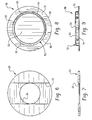
- Figure 6 is a top plan view of a stiffener disc;
- Figure 7 is a side elevational view thereof;
- Figure 8 is a top plan view of a cap member;
- Figure 9 is a side elevational view thereof;
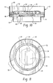
- Figure 10 is a side elevational view of the switch components assembled into a plastic grommet and with the plastic grommet cut-away for clarity of illustration;
- Figure 11 is a top plan view of Figure 10 with portions shown in dotted lines interiorly of the switch for clarity of illustration; and
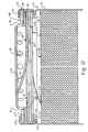
- Figure 12 is a cross-sectional elevational view showing the switch assembly of the present application crimped into the upper end of a battery case.
-
- Referring now to the drawing, wherein the showings are for purposes of illustrating a preferred embodiment of the invention only and not for purposes of limiting same, Figure 1 shows an assembly grommet 10 of a suitable relatively soft and deformable plastic material such as polypropylene. Grommet 10 has a cylindrical
peripheral wall 12 with acircular support flange 14 extending inwardly therefrom. Another cylindricalperipheral wall 16 having a smaller diameter thanwall 12 depends from the inner periphery ofsupport flange 14. - A flat metal stiffener plate or
disc 20 is positionable againstsupport flange 14 withinperipheral wall 12 of assembly grommet 10. The diameter ofstiffener disc 20 is such that it is closely received withinperipheral wall 12. Adiametrical recess 22 extends acrossstiffener disc 20, and a central circular opening is provided therethrough as indicated at 24. - An
actuator member 30 of shape memory metal has aflat mounting base 32 with opposite flat faces, substantially parallelopposite sides opposite ends Opposite ends stiffener disc 20. In addition, the length ofactuator member 30 is such thatcurved ends stiffener disc 20.Base 32 ofactuator member 30 has atransverse slit 37 therein that extends substantially perpendicular toopposite sides longitudinal slit 38 that extends substantially parallel toopposite sides resilient actuator blade 39 that is bent upwardly out of the plane offlat base 32. - Recess 22 in
stiffener disc 20 has a recess depth that is substantially the same as the thickness ofbase 32 ofactuator member 30. Whenbase 32 ofactuator member 30 is received withinrecess 22, the upper outer surface ofbase 32 is substantially flush with the upper outer surface ofstiffener disc 20. - An
insulator ring 46 of a suitable insulating material such as a polyamide has a centralcircular opening 47 and is positionable against the upper surfaces ofstiffener disc 20 andbase 32 ofactuator member 30. The outer periphery ofinsulator ring 46 has substantially the same diameter as the outer periphery ofstiffener disc 20. - A dished
metal cap member 50 has a flat circularperipheral portion 51 with an outer diameter that is substantially the same as the diameter ofstiffener disc 20. Capmember 50 has acentral domed portion 52 with a flatouter surface 53 and aperipheral wall 54 having a plurality of circumferentially-spacedholes 55 therethrough. -
Peripheral portion 51 ofcap member 50 is positionable againstinsulator ring 46 withinperipheral wall 12 ofassembly grommet 10. Analuminum retainer ring 60 is positionable withinperipheral wall 12 of assembly grommet 10 on top of flatperipheral portion 51 ofcap member 50.Retainer ring 60 has a diameter slightly larger than the interior diameter ofperipheral wall 12 on assembly grommet 10 so thatretainer ring 60 must be forced into the cylindrical opening provided byperipheral wall 12. This provides radial forces betweenretainer ring 60 andperipheral wall 12 on assembly grommet 10 to prevent movement or displacement ofretainer ring 60 which holds all of the components withinperipheral wall 12 under light compression. Obviously,retainer ring 60 may be a split ring that can be reduced in diameter for insertion intoperipheral wall 12 and then expand radially into engagement with the wall. Many other retainer arrangements also are possible. - When the switch assembly also is to provide protection against excessive pressure, an aluminum
foil rupture disc 61 is positioned ongrommet support flange 14, andstiffener disc 20 goes on top of the foil rupture disc.Foil rupture disc 61 has acentral protuberance 62 that extends into opening 24 instiffener disc 20.Top portion 63 ofprotuberance 62 is depressed down withinprotuberance 62 and ruptures when subjected to excessive pressure within the battery. The pressure is relieved through vent holes 55 incap member 50. When the switch assembly is to be used in battery applications without a foil rupture disc,central opening 24 instiffener disc 20 is omitted. - Figure 12 shows a battery B having a
battery case 110 with an upper portion that is circumferentially deformed inwardly as generally indicated at 112 to form a grommet support bead that provides ashoulder 114 on whichsupport flange 14 ofassembly grommet 10 is positionable. Thatportion 116 of the battery case extending upwardly fromshoulder 114 then is crimped inwardly and downwardly while deforming grommetperipheral wall 12 into engagement with the outer surface ofperipheral portion 51 oncap member 50. The periphery of the switch assembly is then sealed betweengrommet support flange 14 and the crimpedportion 116 of the battery case. This deformation of grommetperipheral wall 12 cooperates withsupport flange 14 to provide a generally U-shaped annular groove in which the peripheral portion of the other switch components are received and sealed. The generally U-shaped groove and the peripheral portions of the components received therein are under axial compression by virtue of the crimpedportion 116 of the battery case. A separate crimp ring also may be used to form a switch assembly independent of the battery case. - The switch assembly of the present application can be constructed as a normally open switch rather than as a normally closed switch by training the actuator blade to assume the curved shape shown in the drawings instead of moving back toward a flat position at the austenite transition temperature. The switch also is preferably a one-shot type that remains open once the austenite transition temperature is reached. However, it will be recognized that it can be constructed to reclose and to cycle between closed and open positions if so desired.
-
Stiffener disc 20 preferably is of copper although it will be recognized that other materials may be used such as nickel or silver plated cold rolled steel.Actuator 30 preferably is of nickel titanium shape memory metal and it will be recognized that other shape memory metals may be used.Actuator 30 preferably is plated with a precious metal such as silver or gold, although it will be appreciated that it may be possible to coat the actuator with a precious metal in other ways such as by sputtering or vapor deposition. It is important that the precious metal coating be on the peripheral surfaces as well as the faces so that current is conducted from the precious metal on one face to the precious metal on the opposite face through the peripheral precious metal as well as through the shape memory metal. - Examples of some dimensions will be given simply by way of illustration and not by way of limitation, and it will be recognized that the example dimensions may vary by several thousandths of an inch. With reference to Figures 6 and 7, generally rectangular
diametrical recess 22 has a depth of about 0.008 inch while the maximum thickness ofactuator member 30 is about 0.010 inch. This makes the outer surfaces of the stiffener disc and the actuator member substantially flush with one another. -
Recess 22 instiffener disc 20 has a width of about 0.290 inch while the width ofactuator member 30 is about 0.200 inch. Thus, the recess is actually about 45% wider than the actuator member in this example and preferably is at least 20% wider. This facilitates assembly of the components because the actuator member may be dropped into the stiffener disc within the grommet and it will easily fall into the recess. The actuator member is self-centering because its curved ends correspond to the curvature of the inner periphery of grommetperipheral wall 12. - With reference to Figures 2-5, slits 37 and 38 each has a width of about 0.02 inch. Longitudinal slit 38 is located between
longitudinal centerline 31 andside 33, and has a length of about 0.25 inch.Slit 38 is closer to centerline 31 than toside 33.Transverse slit 37 has a length of about 0.14 inch, and is located approximately midway betweentransverse centerline 32 andend 35. The overall length ofactuator 30 between ends 35 and 36 alonglongitudinal centerline 31 is about 0.627 inch. - When the switch is assembled, the end of
resilient actuator blade 39 makes essentially line contact with the interior surface ofcap member 50 with a contact force of at least 150 grams. The resistance of the switch assembly between the stiffener disc and the cap, or between the rupture disc and the cap, is not greater than 50 milliohms and preferably much lower. Depending on the size and the switch assembly, it may have a continuous current rating up to about 3 amps or up to about 20 amps. The resistance of less than 50 milliohms is in the relatively loose assembly of the components into the plastic assembly grommet as shown in Figure 10. The peripheral portions of the components are under relatively light compression that is provided byretainer ring 60 compressing the other components againstsupport flange 14. When the components are under high compression by being peripherally and axially crimped within a battery case as shown in Figure 12 or within a separate crimp ring, the resistance is less than 20 milliohms and more preferably less than 10 milliohms. The resistance can be made even lower by plating all surfaces of other components with a precious metal, such asrupture disc 61 when it is present,stiffener disc 20 andcap member 50. -
Actuator 30 is stamped to the configuration shown in Figures 2-4 and is then plated with a precious metal. The actuator then is heated to its austenitic transformation temperature followed by cooling to its martensitic temperature.Blade 39 then is bent to the general configuration of Figure 5. When the actuator is subsequently heated to its austenite transformation temperature,blade 39 automatically moves back toward the position of Figures 2-4 and this is its recovered position.Blade 39 could be bent upwardly before heating to the austenite transformation temperature and then bent down flat after cooling. The switch would then be a normally open switch.Blade 39 preferably is under less than 8% bending strain and most preferably less than about 4% bending strain as defined in U.S. patent application serial number 08/850,082 filed May 2, 1997, the disclosure of which is hereby incorporated herein by reference. This makes the switch a one-shot type that remains open once the austenite transformation temperature is reached and does not return to a closed position upon cooling. By exceeding the stated percent strain and by proper training of the shape memory metal, it can be made to function as a switch that will cycle between closed and open positions as it is cooled and heated. - With reference to Figure 12, the crimping of the battery case frequently is referred to as a collet redraw. It will be recognized that the switch can be assembled in other arrangements than into a plastic grommet and can be welded into a battery case rather than being crimped therein.
- A length of
nickel foil 120 is welded at one end to the underside ofstiffener disk 20 or to the rupture disc if it is present. The wrappedmulti-layer assembly 122 that forms the battery electrodes has a length ofnickel foil 124 attached thereto. The lengths of nickel foils 120 and 124 is sufficient to permit welding of same together with the switch assembly held well above the open top of a battery case. After welding, the switch assembly is dropped into the open top of the battery case ontoshoulder 114 of thegrommet support bead 112 followed by crimping ofbattery case portion 116. - The thickness of
actuator member 30 preferably is less than 0.020 inch, more preferably less than 0.015 inch and most preferably not greater than about 0.010 inch. These dimensions may be increased by several thousandths of an inch by the precious metal plating thickness of about 0.001-0.002 inch. Thicker shape memory material does not react as well or move as quickly at the transformation temperature. Thicker material also is less stable because it tends to plastically deform when the blade is bent to its desired radius. - Although the invention has been shown and described with respect to a preferred embodiment, it is obvious that equivalent alterations and modifications will occur to others skilled in the art upon the reading and understanding of this specification. The present invention includes all such equivalent alterations and modifications, and is limited only by the scope of the claims.
Claims (45)
- A thermal switch assembly including a stiffener plate having a plate upper surface, a recess in said plate upper surface, said recess having a recess depth, a current carrying actuator member of shape memory metal having a substantially flat base with a base thickness, said base being received in said recess and said recess depth being substantially the same as said base thickness, said base having a base upper surface that is substantially flush with said plate upper surface, an annular electrical insulator positioned against said plate and base upper surfaces, a cap member positioned against said insulator, and said actuator member having an actuator blade extending past said insulator into engagement with said cap member.
- The switch assembly of claim 1 wherein said recess has a recess width and said actuator blade has a blade width, and said recess width is greater than said blade width.
- The switch assembly of claim 2 wherein said recess width is at least 20% greater than said blade width.
- The switch assembly of claim 1 wherein said actuator blade has upper and lower blade surfaces and a blade periphery, and said upper and lower blade surfaces and said blade periphery being coated with a precious metal.
- The switch assembly of claim 1 including a plastic assembly grommet having a peripheral wall and a support flange extending inwardly from said peripheral wall, and said stiffener plate being positioned against said support flange within said peripheral wall.
- The switch of claim 1 wherein said stiffener plate is a circular disc having a disc periphery and said actuator member has opposite actuator member curved ends, and said disc periphery and said curved ends lie on the periphery of a common circle.
- The switch assembly of claim 1 including a plastic assembly grommet having a peripheral wall and a support flange extending inwardly from said peripheral wall, said stiffener plate being positioned against said support flange within said peripheral wall, and a retainer ring positioned against said cap member on the opposite side thereof from said insulator, said retainer ring being in radial engagement with said peripheral wall.
- The switch assembly of claim 1 wherein said stiffener plate has a central opening there through, and a rupturable foil member positioned against said stiffener plate on the opposite side thereof from said actuator member to normally close said central opening in said stiffener member.
- A thermal switch assembly comprising a plastic assembly grommet having a peripheral wall and a support flange extending inwardly from said peripheral wall, a stiffener disc positioned against said support flange within said peripheral wall, an actuator member of shape memory metal positioned against said stiffener disc on the opposite side thereof from said support flange, an insulator ring positioned against said stiffener disc and said actuator member, and a cap member having a cap member peripheral portion positioned against said insulator ring, said actuator member having a resilient actuator blade extending away from said stiffener disc into engagement with said cap member.
- The switch assembly of claim 9 including a retainer ring positioned against said cap member peripheral portion within said peripheral wall of said assembly grommet, said retainer ring being in radial engagement with said peripheral wall of said assembly grommet.
- The switch assembly of claim 9 wherein said stiffener disc has a diametrical recess therein having a recess depth and said actuator member has an actuator member thickness, said recess depth being substantially the same as said actuator member thickness, and said actuator member being received in said recess.
- The switch assembly of claim 11 wherein said recess has a recess width and said actuator member has an actuator member width, and said recess width being at least 20% greater than said actuator member width.
- The switch assembly of claim 9 wherein said stiffener disc has at least one disc opening therein and further including a rupturable foil member positioned between said stiffener disc and said support flange to normally close said disc opening.
- An actuator member of shape memory metal comprising a base having opposite sides, opposite ends and opposite faces, said base having a transverse slit therein located intermediate said ends and extending from one of said sides toward the other of said sides, a longitudinal slit in said base located intermediate said sides and extending from said transverse slit toward one of said ends, said slits and a portion of said one of said sides forming a periphery of a movable actuator blade having a free end located adjacent said transverse slit, and said movable actuator blade being deformable to move said free end in a direction transversely of said faces.
- The actuator member of claim 14 wherein said movable actuator blade has opposite actuator blade faces, and said opposite actuator blade faces and said movable actuator blade periphery being coated with a precious metal.
- The actuator member of claim 14 wherein said base is substantially flat and said movable actuator blade normally extends out of the plane of said base and deforms back toward the plane of said base responsive to an elevated temperature.
- The actuator member of claim 14 wherein said base has a central longitudinal axis extending in a direction between said opposite ends and said longitudinal slit is located between said axis and one of said opposite sides.
- The actuator member of claim 14 wherein each of said opposite ends is curved to lie on the circumference of a common circle.
- The actuator member of claim 14 wherein said base has a base center located at the midpoint between said opposite ends and said opposite sides, and said ends being curved on a radius that is centered on said base center and has a radius length that is equal to one-half the length of said base.
- The actuator member of claim 14 wherein said transverse slit is located closer to one of said opposite ends than to the other of said opposite ends.
- The actuator member of claim 14 wherein said opposite sides are substantially parallel and said transverse slit extends substantially perpendicular to said opposite sides and said longitudinal slit extends substantially parallel to said opposite sides.
- A thermal switch assembly including a stiffener plate having a plate upper surface, a recess in said plate upper surface, said recess having a recess depth, a current carrying actuator member of shape memory metal having a substantially flat base with a base thickness, said base being received in said recess, an annular electrical insulator positioned against said plate and an upper surface of said base, a cap member positioned against said insulator, and said actuator member having an actuator blade extending past said insulator into engagement with said cap member.
- The switch assembly of claim 22 wherein said recess has a recess width and said actuator blade has a blade width, and said recess width is greater than said blade width.
- The switch assembly of claim 23 wherein said recess width is at least 20% greater than said blade width.
- The switch assembly of claim 22 wherein said actuator blade has upper and lower blade surfaces and a blade periphery, and said upper and lower blade surfaces and said blade periphery being coated with a precious metal.
- The switch assembly of claim 22 including a plastic assembly grommet having a peripheral wall and a support flange extending inwardly from said peripheral wall, and said stiffener plate being positioned against said support flange within said peripheral wall.
- The switch assembly of claim 26 wherein said actuator member cooperates with said peripheral wall to position said actuator member within said grommet.
- The switch assembly of claim 22 wherein said stiffener plate is a circular disc having a disc periphery and said actuator member has opposite actuator member curved ends, and said disc periphery and said curved ends lie on the periphery of a common circle.
- The switch assembly of claim 22 including a plastic assembly grommet having a peripheral wall and a support flange extending inwardly from said peripheral wall, said stiffener plate being positioned against said support flange within said peripheral wall, and a retainer ring positioned against said cap member on the opposite side thereof from said insulator, said retainer ring being in radial engagement with said peripheral wall.
- The switch assembly of claim 22 wherein said stiffener plate has a central opening therethrough, and a rupturable foil member positioned against said stiffener plate on the opposite side thereof from said actuator member to normally close said central opening in said stiffener member.
- The switch assembly of claim 22 wherein said actuator blade is defined by at least one slit in said actuator member.
- The switch assembly of claim 31 wherein said base includes opposite sides, opposite ends and opposite faces, said actuator blade being formed intermediate said opposite ends.
- The switch assembly of claim 32 wherein said actuator blade is defined by a first slit formed in said base and extending inwardly from one of said opposite sides and opposite ends.
- A thermal switch assembly comprising a plastic assembly grommet having a peripheral wall and a support flange extending inwardly from said peripheral wall, an actuator member of shape memory metal supported on said support flange, said peripheral wall cooperates with end portions of said actuator member to position said actuator member, an insulator ring positioned against a surface of said actuator member opposite said support flange, and a cap member having a cap member peripheral portion positioned against said insulator ring, said actuator member having a resilient actuator blade extending away from said stiffener disc into engagement with said cap member.
- The switch assembly of claim 34 including a retainer ring positioned against said cap member peripheral portion within said peripheral wall of said assembly grommet, said retainer ring being in radial engagement with said peripheral wall of said assembly grommet.
- The switch assembly of claim 34 wherein said stiffener disc has a diametrical recess therein having a recess depth and said actuator member has an actuator member thickness, said recess depth being substantially the same as said actuator member thickness, and said actuator member being received in said recess.
- The switch assembly of claim 36 wherein said recess has a recess width and said actuator member has an actuator member width, and said recess width being at least 20% greater than said actuator member width.
- The switch assembly of claim 34 wherein said stiffener disc has at least one disc opening therein and further including a rupturable foil member positioned between said stiffener disc and said support flange to normally close said disc opening.
- A thermal switch assembly comprising a plastic assembly grommet having a peripheral wall and a support flange extending inwardly therefrom, an actuator member of shape memory alloy, an insulator member supported on said actuator member and a cap member supported on said insulator member, said actuator member including an actuating blade extending through said insulator into engagement with said cap member and said peripheral wall being operative to retain said actuator member, said insulator member and said cap member in assembled relationship.
- An actuator member of shape memory metal comprising an elongated base having opposite sides, opposite ends and opposite faces, said base having a slit therein located intermediate said ends and extending inwardly from one of said sides to define a movable actuator blade having a free end, and said movable actuator blade being deformable to move said free end in a direction transversely of said faces.
- The actuator member of claim 40 wherein said movable actuator blade has opposite actuator blade faces, and said opposite actuator blade faces and said movable actuator blade periphery being coated with a precious metal.
- The actuator member of claim 40 wherein said base is substantially flat and said movable actuator blade normally extends out of the plane of said base and deforms back toward the plane of said base responsive to an elevated temperature.
- The actuator member of claim 40 wherein said base has a central longitudinal axis extending in a direction between said opposite ends and said longitudinal slit is located between said axis and one of said opposite sides.
- The actuator member of claim 40 wherein each of said opposite ends is curved to lie on the circumference of a common circle.
- The actuator member of claim 40 wherein said base has a base center located at the midpoint between said opposite ends and said opposite sides, and said ends being curved on a radius that is centered on said base center and has a radius length that is equal to one-half the length of said base.
Applications Claiming Priority (2)
| Application Number | Priority Date | Filing Date | Title |
|---|---|---|---|
| US09/197,031 US6018286A (en) | 1998-11-20 | 1998-11-20 | Thermal switch |
| US197031 | 2005-08-04 |
Publications (1)
| Publication Number | Publication Date |
|---|---|
| EP1005059A1 true EP1005059A1 (en) | 2000-05-31 |
Family
ID=22727735
Family Applications (1)
| Application Number | Title | Priority Date | Filing Date |
|---|---|---|---|
| EP99630090A Withdrawn EP1005059A1 (en) | 1998-11-20 | 1999-11-19 | Thermal switch |
Country Status (5)
| Country | Link |
|---|---|
| US (2) | US6018286A (en) |
| EP (1) | EP1005059A1 (en) |
| JP (1) | JP2000164091A (en) |
| KR (1) | KR20000035594A (en) |
| CA (1) | CA2290207A1 (en) |
Families Citing this family (22)
| Publication number | Priority date | Publication date | Assignee | Title |
|---|---|---|---|---|
| US5844464A (en) * | 1997-11-24 | 1998-12-01 | Therm-O-Disc, Incorporated | Thermal switch |
| US6239686B1 (en) * | 1999-08-06 | 2001-05-29 | Therm-O-Disc, Incorporated | Temperature responsive switch with shape memory actuator |
| US6570749B1 (en) * | 2000-07-14 | 2003-05-27 | Advanced Battery Technology Ltd | Over-current and thermal protection device |
| US6549113B1 (en) * | 2000-09-14 | 2003-04-15 | Eaton Corporation | Sealed electric switch |
| WO2002035618A1 (en) | 2000-10-20 | 2002-05-02 | Rayovac Corporation | Method and apparatus for regulating charging of electrochemical cells |
| US7014432B2 (en) * | 2002-03-28 | 2006-03-21 | Denso Corporation | Fuel pumping unit, with a plurality of commutator brush assemblies with engaging members for restricting brush movement toward the pump motor section |
| KR200296482Y1 (en) * | 2002-08-27 | 2002-11-23 | 텍사스 인스트루먼트 코리아 주식회사 | Overload protector with improved sealing capability |
| TW200525854A (en) * | 2003-08-15 | 2005-08-01 | Rovcal Inc | Method and apparatus for charging electrochemical cells |
| US7244527B2 (en) * | 2003-10-16 | 2007-07-17 | Electro Energy, Inc. | Multi-cell battery charge control |
| JP5011664B2 (en) * | 2005-07-11 | 2012-08-29 | パナソニック株式会社 | Sealed secondary battery |
| US7763375B2 (en) * | 2006-05-24 | 2010-07-27 | Eveready Battery Company, Inc. | Current interrupt device for batteries |
| US8219207B2 (en) * | 2007-03-08 | 2012-07-10 | Medtronic, Inc. | Thermal switch for implantable medical devices |
| US20080254343A1 (en) * | 2007-04-16 | 2008-10-16 | Eveready Battery Company, Inc. | Electrochemical cell with thermal current interrupting switch |
| KR200471327Y1 (en) * | 2009-03-13 | 2014-02-26 | 대성전기공업 주식회사 | Inhibitor switch for a vehicle |
| KR101349013B1 (en) * | 2012-04-23 | 2014-01-10 | 현대자동차주식회사 | Housing for electric and electronic components using shape memory material |
| US9627722B1 (en) | 2013-09-16 | 2017-04-18 | American Lithium Energy Corporation | Positive temperature coefficient film, positive temperature coefficient electrode, positive temperature coefficient separator, and battery comprising the same |
| US12103062B2 (en) | 2014-05-04 | 2024-10-01 | Belvac Production Machinery, Inc. | Forming mold for reduction of parting lines |
| US10020487B2 (en) | 2014-11-25 | 2018-07-10 | American Lithium Energy Corporation | Rechargeable battery with voltage activated current interrupter |
| US10020545B2 (en) | 2014-11-25 | 2018-07-10 | American Lithium Energy Corporation | Rechargeable battery with resistive layer for enhanced safety |
| AU2015353404B2 (en) | 2014-11-25 | 2021-04-01 | American Lithium Energy Corporation | Rechargable battery with internal current limiter and interrupter |
| EP3869600B1 (en) * | 2017-05-01 | 2022-10-19 | American Lithium Energy Corporation | Electrical power system and fuse with negative thermal expansion plate |
| US12230844B2 (en) | 2018-06-25 | 2025-02-18 | American Lithium Energy Corporation | Safety layer for battery cells |
Citations (2)
| Publication number | Priority date | Publication date | Assignee | Title |
|---|---|---|---|---|
| US4855195A (en) * | 1988-07-11 | 1989-08-08 | Eveready Battery Company, Inc. | Electrochemical cell with internal circuit interrupter |
| EP0875913A2 (en) * | 1997-05-02 | 1998-11-04 | Emerson Electric Co. | Thermal switch assembly |
Family Cites Families (47)
| Publication number | Priority date | Publication date | Assignee | Title |
|---|---|---|---|---|
| US2497397A (en) * | 1946-01-19 | 1950-02-14 | Dales George Franklin | Thermostat switch |
| US2743335A (en) * | 1953-09-04 | 1956-04-24 | Gen Motors Corp | Circuit breaker |
| US3213250A (en) * | 1962-11-30 | 1965-10-19 | Texas Instruments Inc | Miniature snap acting thermostatic switch |
| US3474372A (en) * | 1967-02-16 | 1969-10-21 | Crowell Designs Inc | Temperature-responsive switch having self-contained heater |
| US3707694A (en) * | 1970-03-09 | 1972-12-26 | Essex International Inc | Thermally sensitive circuit control apparatus |
| US3805207A (en) * | 1972-05-08 | 1974-04-16 | Gen Electric | Thermoresponsive switch actuator |
| CH537088A (en) * | 1972-09-26 | 1973-05-15 | Sprecher & Schuh Ag | Snap-action switch for a thermal release, especially for motor protection |
| US3801944A (en) * | 1972-09-28 | 1974-04-02 | Tri Men Mfg Inc | Temperature-compensated, thermal-activated time delay switch |
| US3872415A (en) * | 1973-04-16 | 1975-03-18 | Texas Instruments Inc | Relay |
| US4035552A (en) * | 1976-07-23 | 1977-07-12 | Gte Laboratories Incorporated | Electrochemical cell |
| US4188460A (en) * | 1978-05-01 | 1980-02-12 | P. R. Mallory & Co., Inc. | Internal battery fuse |
| CH638101A5 (en) * | 1979-05-21 | 1983-09-15 | Cerberus Ag | FIRE DETECTORS. |
| DE3027304C2 (en) * | 1980-07-18 | 1982-09-30 | Sds-Elektro Gmbh, 8024 Deisenhofen | Electrical multilayer contact |
| US4503131A (en) * | 1982-01-18 | 1985-03-05 | Richardson Chemical Company | Electrical contact materials |
| US4395694A (en) * | 1982-06-23 | 1983-07-26 | Portage Electric Products, Inc. | Thermostat construction employing aramide insulation |
| JPS59191273A (en) * | 1983-04-14 | 1984-10-30 | Toshiba Battery Co Ltd | Nonaqueous solvent cell |
| JPS59203376A (en) * | 1983-05-04 | 1984-11-17 | Toshiba Corp | Nonaqeuous solvent battery |
| US4774151A (en) * | 1986-05-23 | 1988-09-27 | International Business Machines Corporation | Low contact electrical resistant composition, substrates coated therewith, and process for preparing such |
| JPS63175345A (en) * | 1987-01-16 | 1988-07-19 | Matsushita Electric Ind Co Ltd | organic electrolyte battery |
| US4782318A (en) * | 1987-08-12 | 1988-11-01 | Texas Instruments Incorporated | Thermally responsive electric switch apparatus |
| DE3739048C2 (en) * | 1987-11-17 | 2001-08-09 | Buerkert Gmbh | Multi-way valve |
| US4818641A (en) * | 1988-04-04 | 1989-04-04 | Eveready Battery Company | Cell circuit interrupter |
| JPH02126336U (en) * | 1989-01-17 | 1990-10-18 | ||
| US5061914A (en) * | 1989-06-27 | 1991-10-29 | Tini Alloy Company | Shape-memory alloy micro-actuator |
| US4992339A (en) * | 1990-03-14 | 1991-02-12 | Eveready Battery Company, Inc. | Electrochemical cell with circuit disconnect device |
| US4975341A (en) * | 1990-04-03 | 1990-12-04 | Eveready Battery Company, Inc. | Electrochemical cell with circuit disconnect device |
| US5026615A (en) * | 1990-08-06 | 1991-06-25 | Eveready Battery Company, Inc. | Electrochemical cell with disconnect switch device |
| JPH04345724A (en) * | 1991-05-22 | 1992-12-01 | Fujitsu Ltd | Non-destructive fuse |
| US5188909A (en) * | 1991-09-12 | 1993-02-23 | Eveready Battery Co., Inc. | Electrochemical cell with circuit disconnect device |
| JP3203623B2 (en) * | 1992-03-06 | 2001-08-27 | ソニー株式会社 | Organic electrolyte battery |
| US5206622A (en) * | 1992-04-10 | 1993-04-27 | Texas Instruments Incorporated | Protector device with improved bimetal contact assembly and method of making |
| US5268664A (en) * | 1993-01-25 | 1993-12-07 | Portage Electric Products, Inc. | Low profile thermostat |
| US5337036A (en) * | 1993-07-28 | 1994-08-09 | Kuczynski Robert A | Miniaturized thermal protector with precalibrated automatic resetting bimetallic assembly |
| US5567539A (en) * | 1994-05-23 | 1996-10-22 | Fuji Photo Film Co., Ltd. | Non-aqueous secondary cell |
| JP3261688B2 (en) * | 1994-08-23 | 2002-03-04 | キヤノン株式会社 | Secondary battery and method of manufacturing the same |
| JPH08185849A (en) * | 1994-12-27 | 1996-07-16 | Fuji Elelctrochem Co Ltd | Electrochemical element with explosion-proof safety device |
| US5619177A (en) * | 1995-01-27 | 1997-04-08 | Mjb Company | Shape memory alloy microactuator having an electrostatic force and heating means |
| JPH08236102A (en) * | 1995-02-27 | 1996-09-13 | Fuji Elelctrochem Co Ltd | Electrochemical element |
| EP0739047A3 (en) * | 1995-04-21 | 1999-04-07 | Wako Electronics Co., Ltd. | Safety device for use in secondary battery |
| KR0158845B1 (en) * | 1995-07-28 | 1999-02-18 | 배순훈 | An over-load preventing device of lithium battery |
| JPH09106804A (en) * | 1995-10-09 | 1997-04-22 | Wako Denshi Kk | Battery safety device |
| US5825275A (en) * | 1995-10-27 | 1998-10-20 | University Of Maryland | Composite shape memory micro actuator |
| US5879832A (en) * | 1996-10-02 | 1999-03-09 | Duracell Inc. | Current interrupter for electrochemical cells |
| US5691073A (en) * | 1996-04-10 | 1997-11-25 | Duracell Inc. | Current interrupter for electrochemical cells |
| US5750277A (en) * | 1996-04-10 | 1998-05-12 | Texas Instruments Incorporated | Current interrupter for electrochemical cells |
| JPH10154530A (en) * | 1996-11-21 | 1998-06-09 | Ngk Insulators Ltd | Lithium secondary battery |
| US5844464A (en) * | 1997-11-24 | 1998-12-01 | Therm-O-Disc, Incorporated | Thermal switch |
-
1998
- 1998-11-20 US US09/197,031 patent/US6018286A/en not_active Expired - Fee Related
-
1999
- 1999-10-01 US US09/410,596 patent/US6078244A/en not_active Expired - Fee Related
- 1999-11-19 CA CA002290207A patent/CA2290207A1/en not_active Abandoned
- 1999-11-19 KR KR1019990051629A patent/KR20000035594A/en not_active Withdrawn
- 1999-11-19 EP EP99630090A patent/EP1005059A1/en not_active Withdrawn
- 1999-11-22 JP JP11331175A patent/JP2000164091A/en active Pending
Patent Citations (2)
| Publication number | Priority date | Publication date | Assignee | Title |
|---|---|---|---|---|
| US4855195A (en) * | 1988-07-11 | 1989-08-08 | Eveready Battery Company, Inc. | Electrochemical cell with internal circuit interrupter |
| EP0875913A2 (en) * | 1997-05-02 | 1998-11-04 | Emerson Electric Co. | Thermal switch assembly |
Also Published As
| Publication number | Publication date |
|---|---|
| JP2000164091A (en) | 2000-06-16 |
| US6078244A (en) | 2000-06-20 |
| CA2290207A1 (en) | 2000-05-20 |
| KR20000035594A (en) | 2000-06-26 |
| US6018286A (en) | 2000-01-25 |
Similar Documents
| Publication | Publication Date | Title |
|---|---|---|
| US6018286A (en) | Thermal switch | |
| US6570749B1 (en) | Over-current and thermal protection device | |
| US6342826B1 (en) | Pressure and temperature responsive switch assembly | |
| US6294977B1 (en) | Thermal switch assembly | |
| EP3951907A1 (en) | Cylindrical battery gasket for preventing corrosion of battery case, and cylindrical battery comprising same | |
| CN1145230C (en) | Current interrupter for electrochemical cells | |
| US6140903A (en) | Thermal switch | |
| EP0974168B1 (en) | Current interrupter for electrochemical cells | |
| KR102513320B1 (en) | secondary battery | |
| US6191679B1 (en) | Thermal switch assembly | |
| EP4350851A1 (en) | Cylindrical secondary battery | |
| KR20230054005A (en) | Cylindrical secondary battery and manufacturing method of secondary battery | |
| US6548204B1 (en) | Sealed battery | |
| US6084501A (en) | Thermal cutoff switch | |
| JP4651297B2 (en) | battery | |
| EP0918345A1 (en) | Thermal switch assembly | |
| JPS608361Y2 (en) | temperature fuse | |
| JP2002324467A (en) | Thermal protector and method of manufacturing the same |
Legal Events
| Date | Code | Title | Description |
|---|---|---|---|
| PUAI | Public reference made under article 153(3) epc to a published international application that has entered the european phase |
Free format text: ORIGINAL CODE: 0009012 |
|
| AK | Designated contracting states |
Kind code of ref document: A1 Designated state(s): DE ES FR GB IT |
|
| AX | Request for extension of the european patent |
Free format text: AL;LT;LV;MK;RO;SI |
|
| 17P | Request for examination filed |
Effective date: 20001020 |
|
| AKX | Designation fees paid |
Free format text: DE ES FR GB IT |
|
| STAA | Information on the status of an ep patent application or granted ep patent |
Free format text: STATUS: THE APPLICATION IS DEEMED TO BE WITHDRAWN |
|
| 18D | Application deemed to be withdrawn |
Effective date: 20020601 |