EP1004127B1 - Force-responsive detectors and systems - Google Patents
Force-responsive detectors and systems Download PDFInfo
- Publication number
- EP1004127B1 EP1004127B1 EP98938799A EP98938799A EP1004127B1 EP 1004127 B1 EP1004127 B1 EP 1004127B1 EP 98938799 A EP98938799 A EP 98938799A EP 98938799 A EP98938799 A EP 98938799A EP 1004127 B1 EP1004127 B1 EP 1004127B1
- Authority
- EP
- European Patent Office
- Prior art keywords
- sensor
- electrically conductive
- layer
- extending
- sensor according
- Prior art date
- Legal status (The legal status is an assumption and is not a legal conclusion. Google has not performed a legal analysis and makes no representation as to the accuracy of the status listed.)
- Expired - Lifetime
Links
- 125000006850 spacer group Chemical group 0.000 claims description 29
- 239000005357 flat glass Substances 0.000 claims description 10
- 239000000463 material Substances 0.000 claims description 6
- 238000000034 method Methods 0.000 claims description 6
- 238000007789 sealing Methods 0.000 claims description 4
- 239000004020 conductor Substances 0.000 claims 6
- 230000035945 sensitivity Effects 0.000 description 5
- 238000000926 separation method Methods 0.000 description 4
- 238000010276 construction Methods 0.000 description 2
- 238000001514 detection method Methods 0.000 description 2
- 239000011521 glass Substances 0.000 description 2
- 230000004048 modification Effects 0.000 description 2
- 238000012986 modification Methods 0.000 description 2
- 208000027418 Wounds and injury Diseases 0.000 description 1
- 230000006378 damage Effects 0.000 description 1
- 238000010292 electrical insulation Methods 0.000 description 1
- 239000012777 electrically insulating material Substances 0.000 description 1
- 244000144992 flock Species 0.000 description 1
- 208000014674 injury Diseases 0.000 description 1
- 239000004033 plastic Substances 0.000 description 1
- 229920003023 plastic Polymers 0.000 description 1
Images

Classifications
-
- B—PERFORMING OPERATIONS; TRANSPORTING
- B60—VEHICLES IN GENERAL
- B60J—WINDOWS, WINDSCREENS, NON-FIXED ROOFS, DOORS, OR SIMILAR DEVICES FOR VEHICLES; REMOVABLE EXTERNAL PROTECTIVE COVERINGS SPECIALLY ADAPTED FOR VEHICLES
- B60J10/00—Sealing arrangements
-
- B—PERFORMING OPERATIONS; TRANSPORTING
- B60—VEHICLES IN GENERAL
- B60J—WINDOWS, WINDSCREENS, NON-FIXED ROOFS, DOORS, OR SIMILAR DEVICES FOR VEHICLES; REMOVABLE EXTERNAL PROTECTIVE COVERINGS SPECIALLY ADAPTED FOR VEHICLES
- B60J10/00—Sealing arrangements
- B60J10/70—Sealing arrangements specially adapted for windows or windscreens
- B60J10/74—Sealing arrangements specially adapted for windows or windscreens for sliding window panes, e.g. sash guides
-
- E—FIXED CONSTRUCTIONS
- E05—LOCKS; KEYS; WINDOW OR DOOR FITTINGS; SAFES
- E05F—DEVICES FOR MOVING WINGS INTO OPEN OR CLOSED POSITION; CHECKS FOR WINGS; WING FITTINGS NOT OTHERWISE PROVIDED FOR, CONCERNED WITH THE FUNCTIONING OF THE WING
- E05F15/00—Power-operated mechanisms for wings
- E05F15/40—Safety devices, e.g. detection of obstructions or end positions
- E05F15/42—Detection using safety edges
- E05F15/44—Detection using safety edges responsive to changes in electrical conductivity
- E05F15/443—Detection using safety edges responsive to changes in electrical conductivity specially adapted for vehicle windows or roofs
-
- H—ELECTRICITY
- H01—ELECTRIC ELEMENTS
- H01H—ELECTRIC SWITCHES; RELAYS; SELECTORS; EMERGENCY PROTECTIVE DEVICES
- H01H3/00—Mechanisms for operating contacts
- H01H3/02—Operating parts, i.e. for operating driving mechanism by a mechanical force external to the switch
- H01H3/14—Operating parts, i.e. for operating driving mechanism by a mechanical force external to the switch adapted for operation by a part of the human body other than the hand, e.g. by foot
- H01H3/141—Cushion or mat switches
- H01H3/142—Cushion or mat switches of the elongated strip type
-
- E—FIXED CONSTRUCTIONS
- E05—LOCKS; KEYS; WINDOW OR DOOR FITTINGS; SAFES
- E05Y—INDEXING SCHEME ASSOCIATED WITH SUBCLASSES E05D AND E05F, RELATING TO CONSTRUCTION ELEMENTS, ELECTRIC CONTROL, POWER SUPPLY, POWER SIGNAL OR TRANSMISSION, USER INTERFACES, MOUNTING OR COUPLING, DETAILS, ACCESSORIES, AUXILIARY OPERATIONS NOT OTHERWISE PROVIDED FOR, APPLICATION THEREOF
- E05Y2900/00—Application of doors, windows, wings or fittings thereof
- E05Y2900/50—Application of doors, windows, wings or fittings thereof for vehicles
- E05Y2900/53—Type of wing
- E05Y2900/55—Windows
Definitions
- the invention relates to force-responsive longitudinal extending sensor according to the preamble of claim 1, as for example known from US-A-3 270 160.
- Sensors and systems embodying the invention are for use in motor vehicles for detecting the presence of an obstruction in a window opening closable by a motorised window pane.
- sensors and systems may be used in many other applications.
- a force-responsive longitudinally extending sensor comprising first longitudinally extending electrically conductive means, second electrically conductive means extending at least partially along the first means, electrically insulating means positioned between and spacing the first means from longitudinally distributed parts of the second means, the remaining parts of the second means on each longitudinal side of the said longitudinally distributed parts normally being resiliently held spaced apart from the first means but being able to be flexed against the resilience into contact with the first means in response to an applied force.
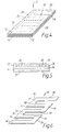
- Figures 1,2 and 3 show one of the sensors. It is of indeterminate length l and predetermined width w . In response to a force applied to it at individual points along its surface and in a direction perpendicular, or at least transverse, to the plane lw , it produces an electrically detectable signal.
- the senor has a rectangular cover layer 10 which is made of flexible and resilient electrically insulating material and extends over the entire upper surface (as viewed in Figures 1 and 2) of the sensor.
- the cover layer 10 is shown as being transparent in order to reveal the construction of the sensor. Normally, however, it would not be transparent.
- a similar cover layer 12 is positioned along the under surface of the sensor (as viewed in Figures 1 and 2); the layer 12 is also electrically non-conductive.
- An electrically conductive layer 14 of rectangular form is mounted on the cover layer 12 and covers substantially its whole length and width.
- the layer 14 is advantageously an electrically conductive film which may be formed by a printed circuit technique on the layer 12.
- Mounted at intervals on and along the conductive layer 14 are electrically insulating spacers 16 which again may be formed by a printed circuit technique.
- Two separate inter-digitated electrically conductive members 18 and 20 are formed on the underside of the layer 10. They are advantageously electrically conductive films which may be formed by a printed circuit technique on the layer 10.
- the shape of the member 18 is shown more clearly in Figure 3. As shown, it comprises an edge portion 22 from which fingers 24 integrally extend. Member 20 is similarly shaped, comprising an edge portion 26 with fingers 28. As shown in Figure 1, members 18 and 20 are arranged so that each finger 24 of the member 18 is positioned between two fingers 28 of the member 20.
- the spacing between the fingers is selected to be sufficiently small to produce the required sensitivity of detection.
- the spacers 16 are shown in Figure 1 as being of thin circular disc-like form. However, they can be of any suitable shape and can be positioned in any way which ensures that the members 18,20 normally are separated from the conductive layer 14 and so that the members 18,20 only make contact with the layer 14 in response to an applied force F.
- the spacers 16 are shaped and positioned so that the width of the area of the sensor which is responsive to an applied force F to be detected is only very slightly less than the overall width w of the sensor. It would of course be possible to insulate the members 18 and 20 from the conductive layer 14 by electrically insulating strips positioned between the edge portion 22 and the layer 14 and positioned between the edge portion 26 and the layer 14. However, in order to provide effective separation and electrical insulation, it would be necessary with such an arrangement to increase the widths of the edge portions 22 and 26, thus increasing the overall width w of the sensor without producing any effective increase in the surface area over which it responds to the applied force F.
- the spacers 16 by being positioned at the roots of the fingers 24,28, provide support over a sufficient total surface area to hold the members 18,20 apart from the layer 14 without significantly affecting the ability of the fingers 24,28 to flex into contact with the layer 14 in response to the applied force.
- the conductive members 18,20 may be replaced by a conductive member or members of any other suitable shape.
- the conductive members 18,20 could be replaced by a single continuous conductive layer or film extending over the area lw and separated from the layer 14 by separated spacers similar to the spacers 16 and either by its own resilience or by the resilience of the cover layer 12 (in the case where the conductive layer is formed on the layer 12).
- the individual spacers 16 of the embodiment of Figures 1,2 and 3 are replaced by a continuous single spacer 32 which is of zig-zag form to define gaps 34 extending widthwise of the sensor and at positions coinciding with the fingers 24 and 28.
- the fingers 24,28 and the remaining parts of the members 18,20 are formed as films on the underside of the insulating cover layer 10.
- the portions 36 of the spacer 32 which run in a longitudinal direction of the sensor are positioned between the conductive layer 14 on the one hand and the edge portions 22,26 of the conductive members 18 and 20 on the other hand.
- the portions 38 of the spacer 32 which run in the transverse direction support the cover layer 10 between the fingers 24,28 and thus indirectly help to support the members 18,20 and maintain their separation from the conductive layer 14.
- the conductive members 18 and 20 are thus electrically insulated by the spacer 32 from the conductive layer 14.
- the cover layer 10 flexes and one or more of the fingers 24,28 is pressed into contact with the conductive layer 14 so as to produce a detectable electrical signal.
- the conductive layer 32 electrically insulates the conductive members 18 and 20 from the conductive layer 14 without increasing the overall width of the sensor. This is achieved by virtue of the additional support provided to the cover layer 10 by the portions 38 of the spacer 32.
- the spacer 32 can be of any suitable shape so as to provide electrically insulating separation between the members 18 and 20 and the layer 14, the support which it provides extending at least partially across the width of the sensor and being shaped so that the support is sufficient without increasing the overall width of the sensor and without reducing its sensitivity to an applied force F.
- the spacer 32 can be formed on the conductive layer 14 by a normal printed-circuit technique. Instead, however, it could be a separate sheet.
- the conductive layers 18,20 could be replaced by one or more conductive members of any suitable shape so as to have conductive portions extending over the gaps in the spacer 32 and supported thereover either by their inherent resilience or by the resilience of the cover layer 12 in the case where the conductive portions are formed as films on the layer 12.
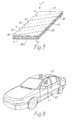
- the individual spacers 16 of Figures 1 to 3 and the spacer 32 of Figures 4 to 6 are replaced by a series of insulating spacers 39 extending widthwise of the sensor at intervals therealong, each spacer being at an angle ⁇ to the length of the sensor.
- the members 18,20 are replaced by a single continuous flexible conductive layer or film 18A extending over substantially the whole of the area lw.
- the spacers 39 in combination with the resilience of the cover layer 10, ensure that there is no normal contact between the members 18A and the conductive layer 14.
- the cover layer 10 flexes and the conductive layer 18A over one or more of the gaps between the spacers 39 is pressed into contact with the conductive layer 14 so as to produce a detectable electrical signal.
- the spacers 39 can be of any suitable cross-section so as to provide electrically insulating separation between the member 18A and the layer 14.
- the spacers 39 can be formed on the layer 14 by a normal printed-circuit technique. Instead, however, they could be formed separately.
- the angle ⁇ can be varied to alter the sensitivity of the sensor without increasing the overall width of the sensor.
- the width of the spacers 80 can be varied with the same result.
- increasing the angle ⁇ and/or increasing the width of the spacers 39 will decrease the sensitivity of the sensor to the applied force F.
- the sensors described above can be designed not only to respond to a force applied to the uppermost surface shown in the Figures but also to a force applied to the undersurface. This can be achieved by making the layers 12 and 14 resiliently flexible.
- the sensors shown in Figures 1 to 7 can be used in many applications where it is required to produce an electrical signal in response to an applied force.
- One particular application will now be described, by way of example only, and relates to the detection of an obstruction in a window opening in a motor vehicle body which is closable by a motorised window glass.
- it is desirable to be able to detect the presence of such an obstruction e.g. part of the human body
- it is desirable to be able to detect the presence of such an obstruction e.g. part of the human body
- a motor vehicle has a door 40 supporting a window frame 42 in which a window glass 44 is upwardly and downwardly slidable.
- the window glass 44 is raised and lowered by means of an electric motor operable under control of an occupant of the vehicle.
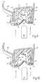
- Figure 9 shows a section through the window frame 42, comprising a rigid mounting channel 46 supported by inner and outer frame members 48 and 49.
- the mounting channel 46 supports a window sealing and guiding channel 50.
- the window channel 50 may be made of extruded or moulded flexible material such as rubber or plastics material.
- the distal edges of the side walls of the channel have outwardly directed lips 52 and 54 which extend over the corresponding edges of the mounting channel 46. Near the base of the channel 50, it has further outwardly directed lips 56 and 58 which engage the curved-over edge regions of the frame members 48 and 49 and resiliently hold the channel 50 within the mounting channel 46.
- the channel 50 also has lips 60 and 62 which extend across the mouth of the channel and a further inner lip 64 near the base of the channel.
- Figure 9 shows the window glass 44 which, as it rises to the closed position, enters the channel 50 with the outer surfaces of the lips 60 and 62 bearing against its opposite faces and the lip 64 bearing against the edge of the glass.
- the surfaces of the lips 60,62,64 which make contact with the glass 44 may be covered with a layer of flock 66 or other similar material.
- a force-responsive sensor 70 is embedded so as to run longitudinally along the length of at least part of the channel 50; advantageously, the sensors run along that part of the channel 50 which extends along the top of the window opening and down the "A" pillar of the vehicle to the region of the rear view mirror.
- each sensor 70 has the form shown in Figures 1,2 and 3, in Figures 4,5 and 6, or in Figure 7.
- This control signal can be used to cause immediate de-energisation of the motor which is raising the window glass, advantageously followed by reversal of the motor to lower it.
- Each sensor 70 is preferably mounted in the channel 50 so that the face shown uppermost in Figures 1,2 and 3, in Figures 4,5 and 6 or in Figure 7 faces downwardly in Figure 9. However, this is not essential because the sensors can be arranged to respond to a force applied to either of its major faces.
- the base of the channel 50 is provided with two longitudinally extending hollow chambers 72 to increase the resilience of the side walls of the channel.
- the additional resilience ensures that only a low reactive force is applied to the obstruction by the window glass during the very short period of time in which it may continue to rise after the sensor 70 has produced the control signal.
- the resilience of the side wall must not be so great as to reduce the sensitivity of the sensors.
- Figure 10 shows a modification in which the chambers 72 are omitted.
Landscapes
- Engineering & Computer Science (AREA)
- Mechanical Engineering (AREA)
- Window Of Vehicle (AREA)
- Force Measurement Appropriate To Specific Purposes (AREA)
- Power-Operated Mechanisms For Wings (AREA)
- Measurement Of Length, Angles, Or The Like Using Electric Or Magnetic Means (AREA)
Description
Claims (23)
- A force-responsive longitudinally extending sensor, comprising first longitudinally extending electrically conductive means (14), second electrically conductive means (18,20;18A) extending at least partially along the first means (14), electrically insulating means (16;32;39) positioned between and spacing the first means (14) from longitudinally distributed parts of the second means (18,20;18A), characterised in that the remaining parts of the second means (18,20;18A) on each longitudinal side of the said longitudinally distributed parts are normally resiliently held spaced apart from the first means (14) but each is able to be flexed against the resilience into contact with the first means (14) in response to an applied force.
- A sensor according to claim 1, characterised in that the electrically insulating means comprises a plurality of discrete insulating means (16;39) spaced longitudinally apart.
- A sensor according to claim 1 or 2, characterised in that the remaining parts of the second means (18,20;18A) comprise fingers (24,28) extending generally perpendicular to the longitudinal direction and extending over the first means (14).
- A sensor according to claim 1, characterised in that the second electrically conductive means comprises a plurality of electrically conductive strips (24 or 28) extending parallel to each other and arranged side by side but with spaces between them along the length of the sensor, the strips being connected to a conductor (22 or 26) extending longitudinally of the sensor.
- A sensor according to claim 4, characterised in that the insulating means comprises a plurality of discrete insulating spacers (16) positioned between respective parts only of at least some of the strips (24 or 28) and the first means (14).
- A sensor according to claim 5, characterised in that the strips (24 or 28) are formed on a flexible resilient layer (10).
- A sensor according to claim 4, characterised in that the strips (24 or 28) are formed on a flexible resilient layer (10), and the insulating means (38) comprises insulating means positioned at the spaces between the conductive strips (24 or 28) and separating the flexible layer (10) from the first means (14), the conductive strips (24 or 28) being held from the first means (14) by the resilience of the flexible layer (10) until the layer (10) is flexed towards the first means (14) by the applied force.
- A sensor according to any one of claims 4 to 7, characterised in that the conductive strips (24 or 28) are in the form of fingers extending from the conductor (22 or 26).
- A sensor according to claim 8, characterised in that there are two conductors (22,26) extending longitudinally of the sensor and parallel to each other and spaced apart, some of the fingers (24) extending from one (22) of the conductors and the other fingers (28) extending from the other conductor (26), the fingers (24,28) being interdigitated.
- A sensor according to claim 4, characterised in that the conductive strips are in the form of fingers (24 or 28) extending from the conductor (22 or 26) and in which the electrically insulating means (16) comprises discrete insulating means, each positioned adjacent a root of a respective one of the fingers )24 or 28).
- A sensor according to claim 7, characterised in that the electrically insulating means comprises an electrically insulating layer (32) positioned between the first electrically conductive means (14) and the flexible resilient layer (10), the insulating layer (32) being provided with gaps (34) corresponding with the positions of the strips (24,28) to enable the strips (24,28) to flex therethrough into contact with the first electrically conductive means (14) in response to the force.
- A sensor according to any preceding claim, characterised in that the first electrically conductive means comprises an electrically conductive layer (14) of generally rectangular configuration with the electrically insulating means (16;32;39) placed thereon and overlain by the second electrically conductive means (18,20;18A), the electrically insulating means (16;32;39) and the second electrically conductive means (18,20;18A) lying within the width of the conductive layer (14).
- A sensor according to claim 2, characterised in that the first electrically conductive means comprises an electrically conductive layer (14) of generally rectangular configuration with the electrically insulating means (39) placed thereon and overlain by the second electrically conductive means (18A), the electrically insulating means (39) and the second electrically conductive means (18A) lying within the width of the conductive layer, the second electrically conductive means (18A) comprising a layer substantially co-extensive with the first-mentioned conductive layer (14).
- A sensor according to claim 2, characterised in that each of the discrete insulating means (39) extends across the width of the sensor.
- A sensor according to claim 14, characterised in that each of the discrete insulating means (39) is positioned at an oblique angle to the longitudinal direction of the sensor.
- A sensor according to any preceding claim, characterised in that the electrically conductive means (14;18,20;18A) are applied using a printed-circuit technique.
- A safety system for detecting an obstruction in a framed opening closable by a motor-driven slidable closure member (44), characterised by a sensor (70) according to any preceding claim mounted on or adjacent the frame (42) of the opening and so positioned that a said force is applied thereto when an obstruction within the opening is carried towards the frame (42) by the sliding closable member (44), and control means responsive to the said contact between the second electrically conductive means (18,20;18A) and the first electrically conductive means (14) to arrest motor-driven movement of the closable member (14).
- A system according to claim 17, characterised by a flexible guiding and sealing channel (50) mounted on the frame (42) for receiving an edge of the closure member (44) which enters the mouth of the channel (50) defined between parallel longitudinally extending distal edges of the side walls of the channel (50), the sensor (70) being mounted on the channel to run longitudinally along or immediately adjacent to one of the distal edges.
- A system according to claim 18, characterised by another, similar, sensor (70), correspondingly mounted in or immediately adjacent to the other distal edge.
- A system according to claim 18 or 19, characterised in that the or each sensor (70) is embedded within the material of the channel immediately adjacent the or the respective distal edge.
- A system according to any one of claims 18 to 20, characterised in that the outside of the base of the guiding and sealing channel (50) is mounted on rigid mounting means (46) forming part of the frame (42) and in that the material forming the base of the guiding and sealing channel (50) defines hollow chamber means (72) positioned substantially at the junction of the base and each channel side wall.
- A system according to any one of claims 17 to 21, characterised in that the framed opening is a window opening and the closure member (44) is a pane of window glass.
- A system according to claim 22, characterised in that the window opening is a window opening in a motor vehicle.
Applications Claiming Priority (5)
| Application Number | Priority Date | Filing Date | Title |
|---|---|---|---|
| GBGB9717280.3A GB9717280D0 (en) | 1997-08-14 | 1997-08-14 | Force-responsive detectors and systems |
| GB9717280 | 1997-08-14 | ||
| GB9720808A GB2328318B (en) | 1997-08-14 | 1997-09-30 | Force-responsive detectors and systems |
| GB9720808 | 1997-09-30 | ||
| PCT/GB1998/002424 WO1999009570A1 (en) | 1997-08-14 | 1998-08-12 | Force-responsive detectors and systems |
Publications (2)
| Publication Number | Publication Date |
|---|---|
| EP1004127A1 EP1004127A1 (en) | 2000-05-31 |
| EP1004127B1 true EP1004127B1 (en) | 2002-03-20 |
Family
ID=26312070
Family Applications (1)
| Application Number | Title | Priority Date | Filing Date |
|---|---|---|---|
| EP98938799A Expired - Lifetime EP1004127B1 (en) | 1997-08-14 | 1998-08-12 | Force-responsive detectors and systems |
Country Status (10)
| Country | Link |
|---|---|
| US (1) | US6281455B1 (en) |
| EP (1) | EP1004127B1 (en) |
| JP (1) | JP2001516124A (en) |
| CN (1) | CN1086839C (en) |
| AU (1) | AU8740098A (en) |
| BR (1) | BR9811490A (en) |
| CA (1) | CA2296365A1 (en) |
| DE (1) | DE69804320T2 (en) |
| ES (1) | ES2177036T3 (en) |
| WO (1) | WO1999009570A1 (en) |
Families Citing this family (14)
| Publication number | Priority date | Publication date | Assignee | Title |
|---|---|---|---|---|
| GB2335310B (en) * | 1998-03-11 | 2001-09-19 | Draftex Ind Ltd | Force-responsive detectors and systems |
| US6337549B1 (en) * | 2000-05-12 | 2002-01-08 | Anthony Gerald Bledin | Capacitive anti finger trap proximity sensor |
| US6858811B2 (en) * | 2001-06-07 | 2005-02-22 | Bed-Check Corporation | Binary switch apparatus and method for manufacturing same |
| US6696653B1 (en) | 2001-06-07 | 2004-02-24 | Bed-Check Corporation | Binary switch apparatus and method for manufacturing same |
| KR20030027588A (en) * | 2001-09-29 | 2003-04-07 | 현대자동차주식회사 | Power window safety system in vehicle |
| US6437263B1 (en) * | 2001-10-11 | 2002-08-20 | Lester E. Burgess | Drape sensor |
| DE10151556A1 (en) * | 2001-10-23 | 2003-04-30 | Bosch Gmbh Robert | Device for opening and closing a moving part |
| US6987232B2 (en) * | 2003-07-14 | 2006-01-17 | Bed-Check Corporation | Sensor and method for detecting a patient's movement via position and occlusion |
| US8134473B2 (en) * | 2008-04-10 | 2012-03-13 | Chg Hospital Beds Inc. | Signaling device for detecting the presence of an object |
| JP6410340B2 (en) * | 2014-04-21 | 2018-10-24 | フォスター電機株式会社 | Cable switch |
| TWI784992B (en) * | 2016-12-27 | 2022-12-01 | 美商康寧公司 | Wireless pressure detector, wireless pressure measuring system, and pressure measuring method |
| KR102410435B1 (en) * | 2017-07-21 | 2022-06-17 | 코닝 인코포레이티드 | Pressure mapping apparatus and method of cleaning a glass substrate using the same |
| EP3787565B1 (en) * | 2018-05-02 | 2024-03-20 | Elastimed Ltd. | A strap having a portion of electro-active polymer, and methodsfor making and using the same |
| IT201800020308A1 (en) * | 2018-12-20 | 2020-06-20 | Axxembla S R L | ELECTRICAL CONTACT SENSITIVE SAFETY DEVICE WITH A PERFECTED SENSITIVE ELEMENT |
Family Cites Families (18)
| Publication number | Priority date | Publication date | Assignee | Title |
|---|---|---|---|---|
| GB630450A (en) | 1947-03-26 | 1949-10-13 | John Leslie Hawkes | Improvements in and relating to electric switching devices for making up into resilient alarm mats |
| GB753018A (en) | 1953-05-08 | 1956-07-18 | Specialities Dev Corp | Electric switch operable by deformation of the housing |
| GB759237A (en) | 1953-12-02 | 1956-10-17 | Specialities Dev Corp | Electric switch operable by deformation of the housing |
| US3270160A (en) | 1965-07-19 | 1966-08-30 | Tapeswitch Corp Of America | Tape switch having zig zag insulator means |
| GB1209564A (en) | 1968-01-31 | 1970-10-21 | Automatic Sliding Door Ltd | Electrical switch mat |
| US4360716A (en) | 1980-10-01 | 1982-11-23 | Texas Instruments Incorporated | Area actuated switch array |
| EP0104414B1 (en) | 1982-08-31 | 1987-05-06 | Erwin Sick GmbH Optik-Elektronik | An elongate resilient section at the closure edge of a closure |
| US4525606A (en) * | 1983-01-28 | 1985-06-25 | Ryoichi Sado | Sensor switch |
| SE512477C2 (en) | 1989-02-22 | 2000-03-20 | Arcus Vita Ab | pressure Sensor |
| US5118910A (en) * | 1990-03-12 | 1992-06-02 | Tapeswitch Corporation Of America | Illuminated, pressure-actuated switch |
| US5307896A (en) | 1991-08-13 | 1994-05-03 | Nippondenso Co., Ltd. | Collision detection sensor |
| GB2261115A (en) | 1991-10-29 | 1993-05-05 | Eja Eng Plc | Pressure sensitive mat |
| US5374796A (en) | 1991-11-27 | 1994-12-20 | Picker International, Inc. | Contact sensor with improved sensitivity |
| DE4329535C2 (en) * | 1993-08-09 | 1998-03-26 | Metzeler Automotive Profiles | Pinch protection for power operated locking devices |
| US5554835A (en) * | 1994-07-27 | 1996-09-10 | Bed-Check Corporation | Traversing conductor pressure sensitive switch |
| GB9509184D0 (en) | 1995-05-05 | 1995-06-28 | Draftex Ind Ltd | Movable window safety device |
| JPH09106731A (en) * | 1995-08-04 | 1997-04-22 | Bridgestone Corp | Cord switch |
| GB9612679D0 (en) | 1996-06-18 | 1996-08-21 | Draftex Ind Ltd | Movable-window safety device |
-
1998
- 1998-08-12 CA CA002296365A patent/CA2296365A1/en not_active Abandoned
- 1998-08-12 ES ES98938799T patent/ES2177036T3/en not_active Expired - Lifetime
- 1998-08-12 BR BR9811490-5A patent/BR9811490A/en not_active IP Right Cessation
- 1998-08-12 WO PCT/GB1998/002424 patent/WO1999009570A1/en not_active Ceased
- 1998-08-12 US US09/445,704 patent/US6281455B1/en not_active Expired - Fee Related
- 1998-08-12 EP EP98938799A patent/EP1004127B1/en not_active Expired - Lifetime
- 1998-08-12 CN CN98808072A patent/CN1086839C/en not_active Expired - Fee Related
- 1998-08-12 JP JP2000510149A patent/JP2001516124A/en active Pending
- 1998-08-12 DE DE69804320T patent/DE69804320T2/en not_active Expired - Fee Related
- 1998-08-12 AU AU87400/98A patent/AU8740098A/en not_active Abandoned
Also Published As
| Publication number | Publication date |
|---|---|
| AU8740098A (en) | 1999-03-08 |
| DE69804320T2 (en) | 2002-11-14 |
| EP1004127A1 (en) | 2000-05-31 |
| JP2001516124A (en) | 2001-09-25 |
| CN1266535A (en) | 2000-09-13 |
| CN1086839C (en) | 2002-06-26 |
| US6281455B1 (en) | 2001-08-28 |
| BR9811490A (en) | 2000-09-19 |
| CA2296365A1 (en) | 1999-02-25 |
| ES2177036T3 (en) | 2002-12-01 |
| WO1999009570A1 (en) | 1999-02-25 |
| DE69804320D1 (en) | 2002-04-25 |
Similar Documents
| Publication | Publication Date | Title |
|---|---|---|
| US6281455B1 (en) | Force-responsive detectors and systems | |
| EP1071860B1 (en) | Force-responsive detectors and systems and methods of making them | |
| EP1099231B1 (en) | Force-responsive detectors and systems | |
| EP0823956B1 (en) | Movable-window safety device | |
| US6297743B1 (en) | Force-responsive detectors and systems | |
| GB2328318A (en) | Force-responsive sensor | |
| US5712620A (en) | Glass fracture security system and a resilient sealing means for use therein | |
| MXPA00001492A (en) | Force-responsive detectors and systems | |
| GB2314378A (en) | Vehicle:powered sliding window:detecting obstruction | |
| MXPA00008837A (en) | Force-responsive detectors and systems and methods of making them | |
| CZ440899A3 (en) | Detectors and systems responsive to action of force | |
| EP0342013A2 (en) | Fluid leakage sensor | |
| CZ2001154A3 (en) | Force detectors and systems having such detectors | |
| JPH01311239A (en) | Clamping detecting device for motor-driven opening/ closing device | |
| JPH09268835A (en) | Method and device for preventing a vehicle power window from being caught | |
| CZ20003278A3 (en) | Sensor and system sensitive to force and method of its production | |
| JP2596791B2 (en) | Pressure sensor for electric switchgear | |
| JPH1024732A (en) | Limit switch | |
| JPH09312115A (en) | Cord switch |
Legal Events
| Date | Code | Title | Description |
|---|---|---|---|
| PUAI | Public reference made under article 153(3) epc to a published international application that has entered the european phase |
Free format text: ORIGINAL CODE: 0009012 |
|
| 17P | Request for examination filed |
Effective date: 19991111 |
|
| AK | Designated contracting states |
Kind code of ref document: A1 Designated state(s): DE ES FR IT |
|
| RAP1 | Party data changed (applicant data changed or rights of an application transferred) |
Owner name: GENCORP PROPERTY INC. |
|
| GRAG | Despatch of communication of intention to grant |
Free format text: ORIGINAL CODE: EPIDOS AGRA |
|
| 17Q | First examination report despatched |
Effective date: 20010516 |
|
| GRAG | Despatch of communication of intention to grant |
Free format text: ORIGINAL CODE: EPIDOS AGRA |
|
| GRAG | Despatch of communication of intention to grant |
Free format text: ORIGINAL CODE: EPIDOS AGRA |
|
| GRAH | Despatch of communication of intention to grant a patent |
Free format text: ORIGINAL CODE: EPIDOS IGRA |
|
| GRAH | Despatch of communication of intention to grant a patent |
Free format text: ORIGINAL CODE: EPIDOS IGRA |
|
| GRAA | (expected) grant |
Free format text: ORIGINAL CODE: 0009210 |
|
| AK | Designated contracting states |
Kind code of ref document: B1 Designated state(s): DE ES FR IT |
|
| REF | Corresponds to: |
Ref document number: 69804320 Country of ref document: DE Date of ref document: 20020425 |
|
| ET | Fr: translation filed | ||
| ET | Fr: translation filed | ||
| REG | Reference to a national code |
Ref country code: ES Ref legal event code: FG2A Ref document number: 2177036 Country of ref document: ES Kind code of ref document: T3 |
|
| PLBE | No opposition filed within time limit |
Free format text: ORIGINAL CODE: 0009261 |
|
| STAA | Information on the status of an ep patent application or granted ep patent |
Free format text: STATUS: NO OPPOSITION FILED WITHIN TIME LIMIT |
|
| 26N | No opposition filed |
Effective date: 20021223 |
|
| PGFP | Annual fee paid to national office [announced via postgrant information from national office to epo] |
Ref country code: FR Payment date: 20060808 Year of fee payment: 9 |
|
| PGFP | Annual fee paid to national office [announced via postgrant information from national office to epo] |
Ref country code: IT Payment date: 20060831 Year of fee payment: 9 |
|
| PGFP | Annual fee paid to national office [announced via postgrant information from national office to epo] |
Ref country code: ES Payment date: 20060921 Year of fee payment: 9 |
|
| REG | Reference to a national code |
Ref country code: FR Ref legal event code: TP |
|
| PGFP | Annual fee paid to national office [announced via postgrant information from national office to epo] |
Ref country code: DE Payment date: 20070809 Year of fee payment: 10 |
|
| REG | Reference to a national code |
Ref country code: FR Ref legal event code: ST Effective date: 20080430 |
|
| PG25 | Lapsed in a contracting state [announced via postgrant information from national office to epo] |
Ref country code: FR Free format text: LAPSE BECAUSE OF NON-PAYMENT OF DUE FEES Effective date: 20070831 |
|
| REG | Reference to a national code |
Ref country code: ES Ref legal event code: FD2A Effective date: 20070813 |
|
| PG25 | Lapsed in a contracting state [announced via postgrant information from national office to epo] |
Ref country code: ES Free format text: LAPSE BECAUSE OF NON-PAYMENT OF DUE FEES Effective date: 20070813 |
|
| PG25 | Lapsed in a contracting state [announced via postgrant information from national office to epo] |
Ref country code: DE Free format text: LAPSE BECAUSE OF NON-PAYMENT OF DUE FEES Effective date: 20090303 |
|
| PG25 | Lapsed in a contracting state [announced via postgrant information from national office to epo] |
Ref country code: IT Free format text: LAPSE BECAUSE OF NON-PAYMENT OF DUE FEES Effective date: 20070812 |