EP1003672B1 - Inflatable cushion forming machine - Google Patents
Inflatable cushion forming machine Download PDFInfo
- Publication number
- EP1003672B1 EP1003672B1 EP98912955A EP98912955A EP1003672B1 EP 1003672 B1 EP1003672 B1 EP 1003672B1 EP 98912955 A EP98912955 A EP 98912955A EP 98912955 A EP98912955 A EP 98912955A EP 1003672 B1 EP1003672 B1 EP 1003672B1
- Authority
- EP
- European Patent Office
- Prior art keywords
- cushion
- rolls
- tubular
- thermoplastic material
- pair
- Prior art date
- Legal status (The legal status is an assumption and is not a legal conclusion. Google has not performed a legal analysis and makes no representation as to the accuracy of the status listed.)
- Expired - Lifetime
Links
Images


Classifications
-
- B—PERFORMING OPERATIONS; TRANSPORTING
- B31—MAKING ARTICLES OF PAPER, CARDBOARD OR MATERIAL WORKED IN A MANNER ANALOGOUS TO PAPER; WORKING PAPER, CARDBOARD OR MATERIAL WORKED IN A MANNER ANALOGOUS TO PAPER
- B31D—MAKING ARTICLES OF PAPER, CARDBOARD OR MATERIAL WORKED IN A MANNER ANALOGOUS TO PAPER, NOT PROVIDED FOR IN SUBCLASSES B31B OR B31C
- B31D5/00—Multiple-step processes for making three-dimensional [3D] articles
- B31D5/0039—Multiple-step processes for making three-dimensional [3D] articles for making dunnage or cushion pads
- B31D5/0073—Multiple-step processes for making three-dimensional [3D] articles for making dunnage or cushion pads including pillow forming
-
- B—PERFORMING OPERATIONS; TRANSPORTING
- B65—CONVEYING; PACKING; STORING; HANDLING THIN OR FILAMENTARY MATERIAL
- B65B—MACHINES, APPARATUS OR DEVICES FOR, OR METHODS OF, PACKAGING ARTICLES OR MATERIALS; UNPACKING
- B65B9/00—Enclosing successive articles, or quantities of material, e.g. liquids or semiliquids, in flat, folded, or tubular webs of flexible sheet material; Subdividing filled flexible tubes to form packages
- B65B9/10—Enclosing successive articles, or quantities of material, in preformed tubular webs, or in webs formed into tubes around filling nozzles, e.g. extruded tubular webs
- B65B9/13—Enclosing successive articles, or quantities of material, in preformed tubular webs, or in webs formed into tubes around filling nozzles, e.g. extruded tubular webs the preformed tubular webs being supplied in a flattened state
-
- B—PERFORMING OPERATIONS; TRANSPORTING
- B31—MAKING ARTICLES OF PAPER, CARDBOARD OR MATERIAL WORKED IN A MANNER ANALOGOUS TO PAPER; WORKING PAPER, CARDBOARD OR MATERIAL WORKED IN A MANNER ANALOGOUS TO PAPER
- B31D—MAKING ARTICLES OF PAPER, CARDBOARD OR MATERIAL WORKED IN A MANNER ANALOGOUS TO PAPER, NOT PROVIDED FOR IN SUBCLASSES B31B OR B31C
- B31D2205/00—Multiple-step processes for making three-dimensional articles
- B31D2205/0005—Multiple-step processes for making three-dimensional articles for making dunnage or cushion pads
- B31D2205/0011—Multiple-step processes for making three-dimensional articles for making dunnage or cushion pads including particular additional operations
- B31D2205/0017—Providing stock material in a particular form
- B31D2205/0023—Providing stock material in a particular form as web from a roll
-
- B—PERFORMING OPERATIONS; TRANSPORTING
- B31—MAKING ARTICLES OF PAPER, CARDBOARD OR MATERIAL WORKED IN A MANNER ANALOGOUS TO PAPER; WORKING PAPER, CARDBOARD OR MATERIAL WORKED IN A MANNER ANALOGOUS TO PAPER
- B31D—MAKING ARTICLES OF PAPER, CARDBOARD OR MATERIAL WORKED IN A MANNER ANALOGOUS TO PAPER, NOT PROVIDED FOR IN SUBCLASSES B31B OR B31C
- B31D2205/00—Multiple-step processes for making three-dimensional articles
- B31D2205/0005—Multiple-step processes for making three-dimensional articles for making dunnage or cushion pads
- B31D2205/0011—Multiple-step processes for making three-dimensional articles for making dunnage or cushion pads including particular additional operations
- B31D2205/007—Delivering
-
- B—PERFORMING OPERATIONS; TRANSPORTING
- B31—MAKING ARTICLES OF PAPER, CARDBOARD OR MATERIAL WORKED IN A MANNER ANALOGOUS TO PAPER; WORKING PAPER, CARDBOARD OR MATERIAL WORKED IN A MANNER ANALOGOUS TO PAPER
- B31D—MAKING ARTICLES OF PAPER, CARDBOARD OR MATERIAL WORKED IN A MANNER ANALOGOUS TO PAPER, NOT PROVIDED FOR IN SUBCLASSES B31B OR B31C
- B31D2205/00—Multiple-step processes for making three-dimensional articles
- B31D2205/0005—Multiple-step processes for making three-dimensional articles for making dunnage or cushion pads
- B31D2205/0076—Multiple-step processes for making three-dimensional articles for making dunnage or cushion pads involving particular machinery details
- B31D2205/0082—General layout of the machinery or relative arrangement of its subunits
-
- Y—GENERAL TAGGING OF NEW TECHNOLOGICAL DEVELOPMENTS; GENERAL TAGGING OF CROSS-SECTIONAL TECHNOLOGIES SPANNING OVER SEVERAL SECTIONS OF THE IPC; TECHNICAL SUBJECTS COVERED BY FORMER USPC CROSS-REFERENCE ART COLLECTIONS [XRACs] AND DIGESTS
- Y10—TECHNICAL SUBJECTS COVERED BY FORMER USPC
- Y10T—TECHNICAL SUBJECTS COVERED BY FORMER US CLASSIFICATION
- Y10T156/00—Adhesive bonding and miscellaneous chemical manufacture
- Y10T156/12—Surface bonding means and/or assembly means with cutting, punching, piercing, severing or tearing
- Y10T156/1304—Means making hole or aperture in part to be laminated
Definitions
- the present invention relates to a device for making inflatable packaging material. More particularly, the present invention relates to a device for making cellular inflatable packaging cushions from tubular thermoplastic material.
- Inflatable cushion packaging material has found widespread use in the packaging industry.
- Various forms of inflatable cushions have been proposed for use in protecting articles during shipment.
- One type of inflatable cushion is a multiple use inflatable cushion which is placed around the article to be protected and inflated after the cushion is placed in the shipping container.
- the invention consists in an inflatable cushion filling machine for forming inflated packaging cushions from a roll of tubular thermoplastic material, comprising:
- the film supply section may include a pair of arms having channels or slots for holding a roll of tubular thermoplastic material.
- one of the arms has a brake which maintains constant web tension on the roll of tubular material.
- the first pair of rolls may be a drive roll and a nip roll forming the nip therebetween through which the tubular material also passes and the second pair of rolls may comprise a drive roll and associated nip roll forming a nip therebetween through which the tubular material passes.
- the first drive roll is reversible to apply tension to the web of thermoplastic material while air passes into the tube to form a pre-bubble and separate the sides of the tubular material.
- the means for introducing air into the tubular material between the pairs of rolls may, for example, be a plurality of needles.
- the means for advancing and retracting at least one of the second pair of rolls may be arranged to move the second nip roll toward and away from the second drive roll allowing the tubular material containing a pre-bubble of air to pass.
- the sealing means such as a heat seal band or wire, is displaced transversely across the thermoplastic material, and seals the ends of the cushions above and below the area of the holes made during filling to form the bottom of the cushion.
- the walls of the tubular thermoplastic material separate from each other by the residual air from the filling operation of the previous cushion.
- a perforation knife may be provided to separate each cushion from the next succeeding cushion.
- the present invention also consists in a method for making an inflated packaging cushion in which tubular thermoplastic material is fed through a cushion forming section having a first pair of rolls forming a nip for advancing the tubular thermoplastic material, and a second pair of rolls forming a nip and spaced downstream from said first pair of rolls; comprising the steps of reversibly driving at least one of said rolls of said first pair to apply tension to the portion of tubular thermoplastic material between said pairs of rolls as said material passes through said cushion forming section by introducing an amount of air into said portion of tubular thermoplastic material while said material is held under tension separating the sides of said tubular material from each other; removing said tension from said portion of tubular material while continuing to inflate; sealing across said tubular thermoplastic material to form a seal line and delimit volume serving to form said cushion; and perforating said seal line between each of said cushions from the next cushion; such that, when said inflating step is completed, the delimited volume is formed above and below said inflating point,
- a pair of inflated packaging cushions 10 of the present invention formed from a tube of air impermeable thermoplastic material.
- Each cushion is formed along weld lines 2 and inflated, as will be described hereafter.
- the cushions are formed in a series, attached to each other, and may be separated along perforated line 3 .
- the width and length of the cushions may vary but are generally in the range of 2.54 cm by 2.54 cm to 30.5 cm by 30.5 cm (3" by 3" to 12" by 12")or larger.
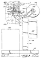
- the inflatable cushion forming machine 100 includes a support 110 , a film supply section 120 , and a cushion forming section 130 .
- the support 110 has a telescoping column 111 mounted to a moveable platform 112 having rollers 113 .
- the telescoping column 111 is adjustable upward and downward over a range of, for example, about 610mm (24 inches). The height of the column will depend upon the height of the product conveyor 114 .
- the moveable platform 112 is positioned adjacent the product conveyor 114 so that the cushion forming section 130 is over the conveyor.
- a container such as, a corrugated box holding an article to be protected
- the operator starts the machine and a series of inflated packaging cushions 10 fall into the container.
- the operator stops the machine and, if necessary, tears the row of cushions at a perforation line 3 and conveys the filled container to a sealing station.
- the operation of the machine is controlled by a controller 115 , which is of conventional design. Because the platform 112 is moveable, the machine 100 can be moved from one product line to another depending upon the need at a given time.
- the film supply section 120 is attached to the top of telescoping column 111 .
- the film supply section 120 includes a pair of arms 123 mounted at the top of the telescoping column 111 and spaced apart from each other a sufficient distance to accommodate a roll 122 of tubular thermoplastic material. As shown more clearly in Figure 5, one arm has a channel 124 for accommodating one end of a roll of film.
- the other arm 123 has a seating member 121 for accommodating a retractable core plug 125 .
- the seating member 121 forms a part of the inner end of brake hub 119 which in turn is attached to one end of hub spring 118 .
- the seating member 121 maintains the roll of material 122 in a secured position and easily releases the core plug by retraction of plunger member 128 capped with hub retraction knob 128a which holds hub spring 118 in place around the outer portion of plunger member 128 .
- a magnetic particle brake 129 which maintains constant web tension between the roll 122 of tubular thermoplastic material and drive roll 134 and nip roll 135 .
- the follower arm 127 is connected through pivot 126 controlled by a potentiometer and connected through a feedback loop to controller 115 which changes the resistance of the brake depending upon the angle of the follower arm against the material roll 122 .
- the brake 129 maintains constant tension on the roll no matter what the diameter.
- the brake 129 continues to apply tension to the roll as the size of the roll decreases through usage.
- the roll of material 122 may have a pair of core plugs 125 inserted in each end of the roll core. When the material roll 122 is placed in the channels 124 , the core plugs 125 rest at the end or bottom of the channel.
- the arms are connected to roll width adjustment pivots 126 which are mounted to the column 111 . The width between the arms 123 may be changed to accommodate different width rolls of material by moving pivots 126 to different fastening positions in the top of column 111 .
- An example of one style of desirable core plug 125 is the spring tensioned plug and the plug seating arrangement shown in U.S.-A-5,322,234,
- the tubular thermoplastic material F is drawn from the film supply section 120 to the cushion forming section 130 .
- the support base 131 of the cushion forming section 130 is mounted at the top of telescoping column 111 in film receiving proximity to the film supply section 120 .
- the cushion forming section 130 includes means for delivering the tubular thermoplastic material F from the roll 122 through the cushion forming section 130 .
- the preferred means is a first pair of rolls 134, 135 forming a nip therebetween through which the tubular material F passes.
- the drive roll is reversibly driven when actuated by motor 137a to provide the required tension of the tubular material during inflation of the cushion.
- Pulley 137 is provided to accommodate belt 138 and is connected to motor 137a and to the controller 115 .
- the drive belt 138 passes around a pulley attached to the end of drive roll 134 , pulley 137 and idle-pulley 136 .
- the film web F tension is not so tight as to prevent a predetermined amount of inflation of air into the area forming the cushion.
- set pin 139 is also provided to position or remove roll 135 and to adjust the tension on roll 135 .
- the material F passes over an idler roll 132 and a dancer roll 133 positioned between the film roll 122 and the first pair of rolls 134, 135 .
- a torsion spring 140 located above dancer roll 132 which serves to maintain the film against the dancer roll.
- nip roll 143 and drive roll 144 are positioned so as to form a nip through which tubular material F passes.
- the second pair of rolls is positioned to form a nip therebetween for drawing the web of thermoplastic film F .
- Rolls 143, 144 are capable of turning in one direction only so as to provide the desired tension.
- Nip roll 143 is connected to pneumatic cylinders 145 , via links 146 , for advancing and retracting the rolls toward and away from each other.
- a jam plate is provided to prevent the thermoplastic material from wrapping around drive roll 144 .
- a jam belt may be provided around one end drive roll 144 .
- a plurality of needles 155 attached through a manifold block 156 connected to an air supply 156A, are held in restraining bar 157 positioned adjacent the channel walls. See Figure 6. While the tubular material F is under tension, pneumatic cylinder 158 moves the needles toward the tubular material piercing only one side thereof, as seen by dotted lines in Figure 6, and inflating the cushion with the desired amount of air.
- a sealing means 150 displaced transversely across the thermoplastic material for delimiting a volume serving to limit the size of the cushion 10 is moved toward the inflated cushion and presses the cushion against the restraining bars 157 to form seal 2 .
- This seal effectively seals the holes made by the needles and leaves residual air in the tube to form the following cushion.
- the sealing means 150 are provided with a pair of sealing bands or wires 152 which when in sealing position are disposed against the surface 151 of restraining bars 157 opposite each other.
- a pneumatic cylinder 154 is provided for advancing and retracting the seal jaws and the perforating knife 160 toward and away from the tubular material.
- the perforation knife 160 is provided for forming perforation line 3 which can be used to separate each cushion for the next succeeding cushion.
- a cover 165 is hingably mounted to the top of the frame support 131.
- a voltage is applied across a metal wire that heats to a desired temperature (or temperature range) when a reasonable voltage is applied.
- Such techniques can be rather crude, however, because simply applying voltage to a wire may heat it to a point where it not only seals the plastic, but also burns the plastic residue, crystallizes the polymer, and breaks the seal itself.
- the wire fails to heat evenly or sufficiently, it may fail to provide a complete seal, leading to other problems, including leakage from the inflatable cushion.
- the present invention also includes a method and apparatus for precisely measuring the characteristics, including, for example, the temperature of a cutting or sealing wire, and then. controlling the wire to maintain it at a desired temperature or temperature range.
- a method and apparatus is provided by the use of a measuring circuit and a storing circuit including a computer chip, such as an EEPROM, in conjunction with an individual heating element, i.e., a metal strip or wire.
- the sealing and band or wire calibrated to obtain measurements concerning the wire's individual characteristics, such as the resistance of the wire through the entire operational range.
- the computer chip is then programmed with the measured characteristics of the individual sealing wire, such as its precise temperature coefficient of resistance. Other information can also be programmed, including the history of the wire's use, as well as other characteristics of the cutting and sealing operation.
- the chip provides the system with the most recent information available concerning the wires used to carry out the cutting and sealing of the plastic for the inflatable cushion operation, so that the appropriate temperature or temperature range may be chosen for the operation of that wire.
- an alternative embodiment of this aspect of the invention records and calibrates the characteristics of motors and other components of the inflatable cushion forming machine.
- the use of smart components provides more precise control for the overall system which, as described above, is often a necessity for a quality final product.
- a particular embodiment of the apparatus for precisely controlling the temperature of a cutting or sealing wire is represented by sealing means 150 shown in Figure 4 and includes a conventional power supply, conventional outputs and an EEPROM(not shown).
- the EEPROM is programmed with information about the individual cutting and sealing wire, which then updates the temperature controlling operation to produce the proper temperature or temperature range.
- the device may also be adapted so that the circuit configuration provides feedback to the EEPROM with updated calibrations from the cutting and sealing wire to control the temperature of the wire.
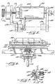
- the inflatable cushion filling machine includes, as shown in Figure 3, a supply of tubular thermoplastic material F from a roll of film 122 which is placed on a delivery rack. At the tubular material delivery site, there is a brake 129 which maintains constant tension between the roll 122 of tubular thermoplastic material and rolls 134 and 135 .
- tubular material F leaves the supply roll 122 , it passes over idler roll 132 and dancer roll 133 where it then passes through the nip formed between rolls 134 and 135 .
- the tubular material then passes between channel walls 141, 142 , which size the preformed bubble inflated by residual air from the previous cycle, and past a second pair of rolls 143, 144 .
- Roll 134 is reversed tensioning the tubular film F between the first pair of rolls and the second pair of rolls.
- the needles 155 are moved toward the web to pierce one side of the web and air is injected.
- the second pair of rolls 143, 144 are moved apart allowing the air to pass to the area within the tubular material below rolls 143, 144 , as shown in Figure 4.
- the film is driven forward a fraction of an inch by drive roll 134 to relieve tension in the tubular material before sealing.
- the needles 155 are still forward (in the pre-bubble) and the nip between the second pair of rolls is open. This allows the tension to be relieved without moving the needle puncture holes out of the area between the seal wires 152.
- the needles retract and the cushion is sealed above and below the needle puncture holes.
- the seal 2 forms the top seal of one inflated cushion and the bottom seal of the next consecutive cushion.
- the perforation knife 160 extends between seal jaws 151 and 152 perforating the seal 2 . Then the seal jaw 151 and 152 and the perforation knife retract and the cycle is repeated or stopped.
Landscapes
- Engineering & Computer Science (AREA)
- Mechanical Engineering (AREA)
- Containers And Plastic Fillers For Packaging (AREA)
- Mattresses And Other Support Structures For Chairs And Beds (AREA)
- Massaging Devices (AREA)
- Buffer Packaging (AREA)
Abstract
Description
- The present invention relates to a device for making inflatable packaging material. More particularly, the present invention relates to a device for making cellular inflatable packaging cushions from tubular thermoplastic material.
- When articles are packaged in a container or box for shipping, there are frequently void spaces in the container. Protective packaging material for articles of different sizes and shapes is commonly used to cushion articles during shipping. There are numerous types and forms of packaging material for this purpose including waste paper, embossed paper, laminated bubble paper and plastic beads, known as peanuts. These forms of packaging material do not always provide the cushioning and void fill needed when shipping.
- Inflatable cushion packaging material has found widespread use in the packaging industry. Various forms of inflatable cushions have been proposed for use in protecting articles during shipment. One type of inflatable cushion is a multiple use inflatable cushion which is placed around the article to be protected and inflated after the cushion is placed in the shipping container.
- Certain advantages, such as ease of use, may be had by using simple, one-use rectangular cellular sealed cushions. Examples of such cellular cushioning materials are shown in U.S. Patent Nos. 3,817,803 and 5,340,632. The ability to make these types of cushions simply, efficiently and at the point of use is of paramount importance One example of such a device is disclosed in EP-B-0 513 235 which describes a machine for making inflatable cushions which includes welding sheets of material together, introducing air to the tubular material and sealing the ends.
- It is an object of the present invention to provide a machine and method for making inflatable, one-use packaging material.
- To this end, the invention consists in an inflatable cushion filling machine for forming inflated packaging cushions from a roll of tubular thermoplastic material, comprising:
- a film supply section having means for holding said roll of tubular thermoplastic material; and
- a cushion forming section comprising;
- a first pair of rolls forming a nip for advancing said tubular thermoplastic material and a second pair of rolls forming a nip positioned downstream and spaced from said first pair of rolls;
- means positioned between said first and second pairs of rolls for introducing air into said tubular thermoplastic material;
- means displaced transversely across said tubular thermoplastic material for delimiting a volume serving to form an inflated cushion, said means forming the top seal of said inflated cushion and the bottom seal of a next cushion; and
- means for advancing and retracting at least one of said second pair of rolls toward and away from each other so that said air may pass into said tubular material forming said cushion and leaving residual air in that portion of said tubular material forming said next cushion; characterised in that at least one of said first pair of rolls is reversibly driven, whereby said first and said second pairs of rolls are capable of providing tension on that portion of said tubular thermoplastic material between said pairs of rolls and said means for introducing air into said tubular thermoplastic material (F) is operable as the latter is held under tension.
-
- The film supply section may include a pair of arms having channels or slots for holding a roll of tubular thermoplastic material. In a preferred embodiment, one of the arms has a brake which maintains constant web tension on the roll of tubular material.
- In the cushion forming section, the first pair of rolls may be a drive roll and a nip roll forming the nip therebetween through which the tubular material also passes and the second pair of rolls may comprise a drive roll and associated nip roll forming a nip therebetween through which the tubular material passes. The first drive roll is reversible to apply tension to the web of thermoplastic material while air passes into the tube to form a pre-bubble and separate the sides of the tubular material.
- While under tension, the upper end and the lower end of the tube are in an airtight relationship between the pairs of rolls. The means for introducing air into the tubular material between the pairs of rolls may, for example, be a plurality of needles. The means for advancing and retracting at least one of the second pair of rolls may be arranged to move the second nip roll toward and away from the second drive roll allowing the tubular material containing a pre-bubble of air to pass. After the tubular material is filled with air, the sealing means, such as a heat seal band or wire, is displaced transversely across the thermoplastic material, and seals the ends of the cushions above and below the area of the holes made during filling to form the bottom of the cushion. As mentioned, prior to filling the cushion with air, the walls of the tubular thermoplastic material separate from each other by the residual air from the filling operation of the previous cushion. A perforation knife may be provided to separate each cushion from the next succeeding cushion.
- The present invention also consists in a method for making an inflated packaging cushion in which tubular thermoplastic material is fed through a cushion forming section having a first pair of rolls forming a nip for advancing the tubular thermoplastic material, and a second pair of rolls forming a nip and spaced downstream from said first pair of rolls; comprising the steps of
reversibly driving at least one of said rolls of said first pair to apply tension to the portion of tubular thermoplastic material between said pairs of rolls as said material passes through said cushion forming section by introducing an amount of air into said portion of tubular thermoplastic material while said material is held under tension separating the sides of said tubular material from each other;
removing said tension from said portion of tubular material while continuing to inflate;
sealing across said tubular thermoplastic material to form a seal line and delimit volume serving to form said cushion; and
perforating said seal line between each of said cushions from the next cushion;
such that, when said inflating step is completed, the delimited volume is formed above and below said inflating point, forming the top seal of said inflated cushion and the bottom seal of the next cushion. - In order that the present invention may be more readily understood, reference will now be made to the accompanying drawings, in which:-
- Figure 1 is an isometric view of a pair of packaging cushions attached to each other and made by the present invention;
- Figure 2 is a front view of a cushion filling machine according to the present invention;
- Figure 3 is a side view of the cushion filling machine;
- Figure 4 is an exploded side view of the cushion filling section of the machine;
- Figure 5 is a top views of the film supply section;
- Figure 6 is a top views of the filling needles, sealing portion and perforating portion of the cushion filling machine taken along line 6-6 of Figure 4; and
- Figure 7 is a fragmentary view taken along line 7-7 of Figure 6.
-
- Referring now to the drawings and in particular Figure 1, there is shown a pair of inflated
packaging cushions 10 of the present invention formed from a tube of air impermeable thermoplastic material. Each cushion is formed along weld lines 2 and inflated, as will be described hereafter. The cushions are formed in a series, attached to each other, and may be separated along perforated line 3. Depending upon the cushioning protection desired, the width and length of the cushions may vary but are generally in the range of 2.54 cm by 2.54 cm to 30.5 cm by 30.5 cm (3" by 3" to 12" by 12")or larger. - As shown in Figures 3 and 4, the inflatable
cushion forming machine 100 includes asupport 110, afilm supply section 120, and acushion forming section 130. Thesupport 110 has a telescoping column 111 mounted to amoveable platform 112 havingrollers 113. The telescoping column 111 is adjustable upward and downward over a range of, for example, about 610mm (24 inches). The height of the column will depend upon the height of the product conveyor 114. Themoveable platform 112 is positioned adjacent the product conveyor 114 so that thecushion forming section 130 is over the conveyor. As a container, such as, a corrugated box holding an article to be protected, passes thecushion forming section 130, the operator starts the machine and a series of inflatedpackaging cushions 10 fall into the container. When a suitable number of cushions has been formed, the operator stops the machine and, if necessary, tears the row of cushions at a perforation line 3 and conveys the filled container to a sealing station. The operation of the machine is controlled by acontroller 115, which is of conventional design. Because theplatform 112 is moveable, themachine 100 can be moved from one product line to another depending upon the need at a given time. - The
film supply section 120 is attached to the top of telescoping column 111. Thefilm supply section 120 includes a pair ofarms 123 mounted at the top of the telescoping column 111 and spaced apart from each other a sufficient distance to accommodate a roll 122 of tubular thermoplastic material. As shown more clearly in Figure 5, one arm has achannel 124 for accommodating one end of a roll of film. Theother arm 123 has aseating member 121 for accommodating aretractable core plug 125. Theseating member 121 forms a part of the inner end ofbrake hub 119 which in turn is attached to one end ofhub spring 118. Theseating member 121 maintains the roll of material 122 in a secured position and easily releases the core plug by retraction ofplunger member 128 capped with hub retraction knob 128a which holdshub spring 118 in place around the outer portion ofplunger member 128. - There is also provided a
magnetic particle brake 129 which maintains constant web tension between the roll 122 of tubular thermoplastic material anddrive roll 134 andnip roll 135. Thefollower arm 127 is connected throughpivot 126 controlled by a potentiometer and connected through a feedback loop tocontroller 115 which changes the resistance of the brake depending upon the angle of the follower arm against the material roll 122. In other words, thebrake 129 maintains constant tension on the roll no matter what the diameter. As shown, thebrake 129 continues to apply tension to the roll as the size of the roll decreases through usage. When the roll 122 of thermoplastic material has been used up a new roll may be easily placed in position onarms 123. - The roll of material 122 may have a pair of core plugs 125 inserted in each end of the roll core. When the material roll 122 is placed in the
channels 124, the core plugs 125 rest at the end or bottom of the channel. The arms are connected to roll width adjustment pivots 126 which are mounted to the column 111. The width between thearms 123 may be changed to accommodate different width rolls of material by movingpivots 126 to different fastening positions in the top of column 111. An example of one style ofdesirable core plug 125 is the spring tensioned plug and the plug seating arrangement shown in U.S.-A-5,322,234, - The tubular thermoplastic material F is drawn from the
film supply section 120 to thecushion forming section 130. Thesupport base 131 of thecushion forming section 130 is mounted at the top of telescoping column 111 in film receiving proximity to thefilm supply section 120. Thecushion forming section 130 includes means for delivering the tubular thermoplastic material F from the roll 122 through thecushion forming section 130. The preferred means is a first pair ofrolls -
Pulley 137 is provided to accommodate belt 138 and is connected to motor 137a and to thecontroller 115. The drive belt 138 passes around a pulley attached to the end ofdrive roll 134,pulley 137 and idle-pulley 136. The film web F tension is not so tight as to prevent a predetermined amount of inflation of air into the area forming the cushion. - As shown in Figures 2 and 4, set
pin 139 is also provided to position or removeroll 135 and to adjust the tension onroll 135. - In order to provide a smooth delivery of the thermoplastic tubular material, the material F passes over an
idler roll 132 and adancer roll 133 positioned between the film roll 122 and the first pair ofrolls dancer roll 132 which serves to maintain the film against the dancer roll. - To form and inflate the cushion, it is necessary to separate the sides of the tubular material F from each other. There are several means for separating the sides of the tubular material from each other, such as by using vacuum cups. However, it has been found that when the tubular material is passed through a channel formed by
walls 141, 142 that a bubble of residual air from the previous cycle is caught between the sides of the tubular material F forcing the sides against thechannel walls 141, 142. - To maintain the tubular material under tension, a second pair of rolls, nip
roll 143 and driveroll 144, are positioned so as to form a nip through which tubular material F passes. The second pair of rolls is positioned to form a nip therebetween for drawing the web of thermoplasticfilm F. Rolls rolls roll 143 is connected topneumatic cylinders 145, vialinks 146, for advancing and retracting the rolls toward and away from each other. To prevent the thermoplastic material from wrapping arounddrive roll 144, a jam plate is provided. In addition, a jam belt may be provided around oneend drive roll 144. - Downstream from the
channel walls 141, 142 and before the second pair of drive rolls 143, 144, are the sealing and filling elements. As shown more clearly in Figures 4 and 6-7, there is provided means for introducing air into the tubular thermoplastic material. In a preferred embodiment, a plurality ofneedles 155, attached through amanifold block 156 connected to anair supply 156A, are held in restrainingbar 157 positioned adjacent the channel walls. See Figure 6. While the tubular material F is under tension,pneumatic cylinder 158 moves the needles toward the tubular material piercing only one side thereof, as seen by dotted lines in Figure 6, and inflating the cushion with the desired amount of air. As theneedles 155 are removed, a sealing means 150 displaced transversely across the thermoplastic material for delimiting a volume serving to limit the size of thecushion 10 is moved toward the inflated cushion and presses the cushion against the restrainingbars 157 to form seal 2. This seal effectively seals the holes made by the needles and leaves residual air in the tube to form the following cushion. More specifically, the sealing means 150 are provided with a pair of sealing bands orwires 152 which when in sealing position are disposed against the surface 151 of restrainingbars 157 opposite each other. A pneumatic cylinder 154 is provided for advancing and retracting the seal jaws and the perforatingknife 160 toward and away from the tubular material. - The
perforation knife 160 is provided for forming perforation line 3 which can be used to separate each cushion for the next succeeding cushion. Acover 165 is hingably mounted to the top of theframe support 131. - In the basic operation of the sealing bar; a voltage is applied across a metal wire that heats to a desired temperature (or temperature range) when a reasonable voltage is applied. Such techniques can be rather crude, however, because simply applying voltage to a wire may heat it to a point where it not only seals the plastic, but also burns the plastic residue, crystallizes the polymer, and breaks the seal itself. Alternatively, if the wire fails to heat evenly or sufficiently, it may fail to provide a complete seal, leading to other problems, including leakage from the inflatable cushion.
- The present invention also includes a method and apparatus for precisely measuring the characteristics, including, for example, the temperature of a cutting or sealing wire, and then. controlling the wire to maintain it at a desired temperature or temperature range. Such method and apparatus is provided by the use of a measuring circuit and a storing circuit including a computer chip, such as an EEPROM, in conjunction with an individual heating element, i.e., a metal strip or wire.
- In use, the sealing and band or wire calibrated to obtain measurements concerning the wire's individual characteristics, such as the resistance of the wire through the entire operational range. The computer chip is then programmed with the measured characteristics of the individual sealing wire, such as its precise temperature coefficient of resistance. Other information can also be programmed, including the history of the wire's use, as well as other characteristics of the cutting and sealing operation. The chip provides the system with the most recent information available concerning the wires used to carry out the cutting and sealing of the plastic for the inflatable cushion operation, so that the appropriate temperature or temperature range may be chosen for the operation of that wire.
- Further, an alternative embodiment of this aspect of the invention records and calibrates the characteristics of motors and other components of the inflatable cushion forming machine. The use of smart components provides more precise control for the overall system which, as described above, is often a necessity for a quality final product.
- A particular embodiment of the apparatus for precisely controlling the temperature of a cutting or sealing wire is represented by sealing
means 150 shown in Figure 4 and includes a conventional power supply, conventional outputs and an EEPROM(not shown). The EEPROM is programmed with information about the individual cutting and sealing wire, which then updates the temperature controlling operation to produce the proper temperature or temperature range. The device may also be adapted so that the circuit configuration provides feedback to the EEPROM with updated calibrations from the cutting and sealing wire to control the temperature of the wire. By controlling the temperature of the cutting and sealing wire, a complete and accurate seal and cut can be accomplished by the inflatable cushion forming machine. - The inflatable cushion filling machine includes, as shown in Figure 3, a supply of tubular thermoplastic material F from a roll of film 122 which is placed on a delivery rack. At the tubular material delivery site, there is a
brake 129 which maintains constant tension between the roll 122 of tubular thermoplastic material and rolls 134 and 135. - As the tubular material F leaves the supply roll 122, it passes over
idler roll 132 anddancer roll 133 where it then passes through the nip formed betweenrolls channel walls 141, 142, which size the preformed bubble inflated by residual air from the previous cycle, and past a second pair ofrolls Roll 134 is reversed tensioning the tubular film F between the first pair of rolls and the second pair of rolls. - The
needles 155 are moved toward the web to pierce one side of the web and air is injected. The second pair ofrolls drive roll 134 to relieve tension in the tubular material before sealing. At this point, theneedles 155 are still forward (in the pre-bubble) and the nip between the second pair of rolls is open. This allows the tension to be relieved without moving the needle puncture holes out of the area between theseal wires 152. When that step is complete, the needles retract and the cushion is sealed above and below the needle puncture holes. The seal 2 forms the top seal of one inflated cushion and the bottom seal of the next consecutive cushion. During sealing, theperforation knife 160 extends betweenseal jaws 151 and 152 perforating the seal 2. Then theseal jaw 151 and 152 and the perforation knife retract and the cycle is repeated or stopped.
Claims (9)
- An inflatable cushion filling machine (100) for forming inflated packaging cushions (10) from a roll (122) of tubular thermoplastic material (F), comprising:characterised in that at least one of said first pair of rolls (134,135) is reversibly driven, whereby said first and said second pairs of rolls are capable of providing tension on that portion of said tubular thermoplastic material between said pairs of rolls, and said means for introducing air into said tubular thermoplastic material (F) is operable as the latter is held under tension.a film supply (120) section having means (123) for holding said roll of tubular thermoplastic material; anda cushion forming section (130) comprising:a first pair of rolls (134,135) forming a nip for advancing said tubular thermoplastic material (F) and a second pair of rolls (143,144) forming a nip positioned downstream and spaced from said first pair of rolls (134,135);means (155) positioned between said first and second pairs of rolls for introducing air into said tubular thermoplastic material (F);means (150) displaced transversely across said tubular thermoplastic material (F) for delimiting a volume serving to form an inflated cushion (10), said means forming the top seal of said inflated cushion and the bottom seal of a next cushion; andmeans (145) for advancing and retracting at least one of said second pair of rolls toward and away from each other so that said air may pass into said tubular material (F) forming said cushion (10) and leaving residual air in that portion of said tubular material forming said next cushion;
- The machine according to claim 1, wherein said film supply section (120) includes a brake (129) which maintains constant web tension on said roll (122) of tubular thermoplastic material (F).
- The machine according to claim 1 or 2, wherein said means for holding (123) said roll (122) of tubular material (F) comprises a pair of arms (123), one of said arms having a spring loaded seating member (119) for retaining and releasing a core plug (125).
- The machine according to claim 1, 2 or 3, including a dancer roll (133) and an idler roll (132) positioned between said holding means (123) for said thermoplastic material (F) and said first pair of rolls (134,135).
- The machine according to claim 1, 2, 3 or 4, wherein said means for delimiting said volume serving to form said inflated cushion (10) is a pair of sealing wires (152).
- The machine according to claim 5, including means for applying a voltage to said sealing wires (152) and means for measuring and controlling the temperature of said wires.
- The machine according to any preceding claim, wherein said means for introducing air into said cushion (10) is a plurality of needles (155).
- The machine according to any preceding claim, including a perforation knife (160) for separating said inflated cushions.
- A method for making an inflated packaging cushion (10), in which tubular thermoplastic material (F) is fed through a cushion forming section (130) having a first pair of rolls (134,135) forming a nip for advancing the tubular thermoplastic material, and a second pair of rolls (143, 144) forming a nip and spaced downstream from said first pair of rolls; comprising the steps of:reversibly driving at least one of said rolls of said first pair to apply tension to the portion of tubular thermoplastic material between said pairs of rolls as said material passes through said cushion forming sectionintroducing an amount of air into said portion of tubular thermoplastic material while said material is held under tension separating the sides of said tubular material from each other;removing said tension from said portion of tubular material while continuing to inflate;sealing across said tubular thermoplastic material to form a seal line and delimit volume serving to form said cushion (10); andperforating said seal line between each of said cushions from the next cushion;such that, when the inflating step is completed, the delimited volume is formed above and below the zone of introduction of the air, forming the top seal of said inflated cushion and the bottom seal of the next cushion.
Applications Claiming Priority (3)
| Application Number | Priority Date | Filing Date | Title |
|---|---|---|---|
| US816272 | 1997-03-13 | ||
| US08/816,272 US5942076A (en) | 1997-03-13 | 1997-03-13 | Inflatable cushion forming machine |
| PCT/US1998/005280 WO1998040276A1 (en) | 1997-03-13 | 1998-03-13 | Inflatable cushion forming machine |
Publications (3)
| Publication Number | Publication Date |
|---|---|
| EP1003672A1 EP1003672A1 (en) | 2000-05-31 |
| EP1003672B1 true EP1003672B1 (en) | 2003-01-22 |
| EP1003672B9 EP1003672B9 (en) | 2003-05-07 |
Family
ID=25220136
Family Applications (1)
| Application Number | Title | Priority Date | Filing Date |
|---|---|---|---|
| EP98912955A Expired - Lifetime EP1003672B9 (en) | 1997-03-13 | 1998-03-13 | Inflatable cushion forming machine |
Country Status (9)
| Country | Link |
|---|---|
| US (1) | US5942076A (en) |
| EP (1) | EP1003672B9 (en) |
| JP (1) | JP4083237B2 (en) |
| AT (1) | ATE231460T1 (en) |
| AU (1) | AU6762598A (en) |
| BR (1) | BR9808223A (en) |
| CA (1) | CA2282716C (en) |
| DE (1) | DE69810932T2 (en) |
| WO (1) | WO1998040276A1 (en) |
Families Citing this family (81)
| Publication number | Priority date | Publication date | Assignee | Title |
|---|---|---|---|---|
| US6536183B1 (en) | 1998-12-21 | 2003-03-25 | Free-Flow Packaging International, Inc. | Air-filled packing cushion delivery system |
| US6519916B1 (en) * | 1998-12-21 | 2003-02-18 | Free-Flow Packaging International, Inc. | System and method for conveying air-filled packing cushions |
| NL1011095C2 (en) * | 1999-01-20 | 2000-07-21 | Free Flow Packaging Int Inc | Device for manufacturing cushions filled with a gaseous medium. |
| US7536837B2 (en) * | 1999-03-09 | 2009-05-26 | Free-Flow Packaging International, Inc. | Apparatus for inflating and sealing pillows in packaging cushions |
| NL1011809C2 (en) | 1999-04-15 | 2000-10-17 | Cps Case Packaging Sales Europ | Device for manufacturing cushions filled with a gaseous medium. |
| CA2384976A1 (en) * | 1999-09-22 | 2001-03-29 | Ambassador Packaging Limited | Method and machine for the manufacture of air pillows |
| US8627637B2 (en) * | 1999-09-22 | 2014-01-14 | Pregis Innovative Packaging, Inc. | Method and machine for the manufacture of air pillows |
| US6719867B1 (en) | 2000-01-14 | 2004-04-13 | Robert J. Mileti | Heat sealer for thermoplastic films |
| WO2001053153A1 (en) * | 2000-01-20 | 2001-07-26 | Free-Flow Packaging International, Inc. | System, method and material for making pneumatically filled packing cushions |
| US6276532B1 (en) | 2000-03-15 | 2001-08-21 | Sealed Air Corporation (Us) | Inflatable packaging cushion with a resistance wire |
| US6569283B1 (en) | 2000-03-15 | 2003-05-27 | Sealed Air Corporation (Us) | Inflator/sealer device for inflatable packaging cushion |
| EP1320495B1 (en) * | 2000-09-27 | 2005-03-02 | Johannes LÖRSCH | Gas filled bodies |
| US6410119B1 (en) | 2000-11-21 | 2002-06-25 | Free-Flow Packaging International, Inc. | Inflatable, cushioning, bubble wrap product having multiple, interconnected, bubble structures |
| US6675557B2 (en) | 2001-01-12 | 2004-01-13 | Sealed Air Corporation (Us) | Apparatus for dispensing fluid into pre-formed, flexible containers and enclosing the fluid within the containers |
| US6598373B2 (en) | 2001-02-13 | 2003-07-29 | Sealed Air Corporation (Us) | Apparatus and method for forming inflated containers |
| US6651406B2 (en) | 2001-02-13 | 2003-11-25 | Sealed Air Corporation (Us) | Apparatus and method for forming inflated containers |
| GB0107984D0 (en) * | 2001-03-30 | 2001-05-23 | Easypack Ltd | Air bags |
| US7220476B2 (en) | 2001-05-10 | 2007-05-22 | Sealed Air Corporation (Us) | Apparatus and method for forming inflated chambers |
| US7174696B2 (en) * | 2002-03-01 | 2007-02-13 | Free-Flow Packaging International, Inc. | Machine and method for inflating and sealing air-filled packing cushions |
| US6929193B2 (en) | 2002-03-13 | 2005-08-16 | Sealed Air Corporation | Tip for a foam-in-place dispenser |
| GB2387423B (en) * | 2002-04-12 | 2005-06-22 | Green Light Packaging Ltd | Apparatus and method for forming void-fill packaging |
| US6726364B2 (en) * | 2002-09-19 | 2004-04-27 | Poppack, Llc | Bubble-seal apparatus for easily opening a sealed package |
| US7302784B2 (en) * | 2002-09-27 | 2007-12-04 | Depuy Products, Inc. | Vacuum packaging machine |
| US6932134B2 (en) * | 2003-02-07 | 2005-08-23 | Pactiv Corporation | Devices and methods for manufacturing packaging materials |
| US7213383B2 (en) * | 2003-05-09 | 2007-05-08 | Intellipack | Bag forming system edge seal |
| EP1636658B1 (en) * | 2003-05-09 | 2009-04-15 | Intellipack, Inc. | Operational control system and system for remote control of a foam dispenser |
| US8124915B2 (en) * | 2003-05-09 | 2012-02-28 | Pregis Intellipack Corporation | Sealing device |
| US20050044813A1 (en) * | 2003-09-03 | 2005-03-03 | Hamid Noorian | Method for manufacturing, assembling, and encapsulating non-combustible, non-toxic and lighter than air gases in a bubble wrap or pouch form for reduction of shipping costs |
| US6996955B2 (en) * | 2003-09-12 | 2006-02-14 | Sealed Air Corporation (Us) | System for conveying packaging cushions |
| US20050167040A1 (en) * | 2004-02-04 | 2005-08-04 | Skymark Packaging Systems Inc. | Layered web sealing and severing head |
| US7273142B2 (en) * | 2004-02-17 | 2007-09-25 | Sealed Air Corporation (Us) | Packaging cushion delivery system |
| US20050210839A1 (en) * | 2004-03-24 | 2005-09-29 | Sealed Air Corporation (Us) | Overhead packaging cushion supply system |
| US7571589B2 (en) * | 2004-07-15 | 2009-08-11 | Storopack, Inc. | Apparatus for and method of producing and/or separating a string of interconnected packing cushions |
| AU2005203038A1 (en) * | 2004-07-15 | 2006-02-02 | Sealed Air Corporation (Us) | High-speed apparatus and method for forming inflated chambers |
| US7040073B2 (en) | 2004-08-30 | 2006-05-09 | Free-Flow Packaging International | Machine for inflating and sealing air-filled cushioning materials |
| US7231749B2 (en) * | 2004-09-02 | 2007-06-19 | Sealed Air Corporation (Us) | Apparatus and system for detecting under-filled cushions |
| US8020358B2 (en) * | 2004-11-02 | 2011-09-20 | Sealed Air Corporation (Us) | Apparatus and method for forming inflated containers |
| US7621104B2 (en) * | 2005-01-31 | 2009-11-24 | Sealed Air Corporation (Us) | Inflatable mailer, apparatus and method for preparing the same |
| US7165375B2 (en) * | 2005-02-05 | 2007-01-23 | Sealed Air Corporation (Us) | Inflation device for forming inflated containers |
| NZ561024A (en) * | 2005-03-12 | 2009-12-24 | Sealed Air Corp | Inflatable containers |
| US20060210738A1 (en) * | 2005-03-21 | 2006-09-21 | Jean-Marc Slovencik | Stock material, inflatable cushioning product, and method |
| US20060218879A1 (en) * | 2005-03-31 | 2006-10-05 | Sealed Air Corporation (Us) | Apparatus for forming inflated packaging cushions |
| US7225599B2 (en) | 2005-04-05 | 2007-06-05 | Sealed Air Corporation | Apparatus and method for forming inflated articles |
| DE202005006427U1 (en) * | 2005-04-21 | 2005-07-21 | LÖRSCH, Johannes | Apparatus for producing gas-filled packing |
| US7862870B2 (en) * | 2005-05-06 | 2011-01-04 | Pregis Innovative Packaging, Inc. | Films for inflatable cushions |
| CA2620800A1 (en) * | 2005-09-12 | 2007-03-22 | Sealed Air Corporation (Us) | Flexible valves |
| US7299103B1 (en) | 2006-07-12 | 2007-11-20 | Sealed Air Corporation (Us) | System and method for monitoring consumable usage in packaging machines |
| WO2008034089A2 (en) * | 2006-09-15 | 2008-03-20 | Polyair Corporation | Air packing machine and method using ultrasonic sealing |
| DE502007001103D1 (en) * | 2006-09-26 | 2009-09-03 | Johannes Loersch | Apparatus and method for producing gas-filled packing |
| EP2404834B1 (en) | 2006-10-04 | 2014-06-18 | Pregis Innovative Packaging Inc. | Automated air-pillow dispenser |
| US7503156B2 (en) * | 2007-01-11 | 2009-03-17 | Ralph Eibert | Method and apparatus for making dunnage |
| US8567159B2 (en) | 2007-04-12 | 2013-10-29 | Sealed Air Corporation (Us) | Apparatus and method for making inflated articles |
| US7490449B1 (en) * | 2007-08-13 | 2009-02-17 | Ralph Eibert | Method and apparatus for making dunnage |
| NL1034305C2 (en) * | 2007-08-29 | 2009-03-03 | Ideepak Holding B V | Device for inflating tubular foil for manufacturing packaging material, as well as a method for inflating tubular foil with such a device. |
| US7914239B2 (en) | 2007-12-20 | 2011-03-29 | Sealed Air Corporation (Us) | Conveyance system for web of packaging cushions |
| US9381715B2 (en) | 2008-09-03 | 2016-07-05 | Free-Flow Packaging International, Inc. | Method and apparatus for inflating and sealing packing cushions with rotary sealing mechanism |
| CN102171103B (en) * | 2008-09-03 | 2016-01-20 | 福利弗罗包装国际有限公司 | Method and Apparatus for Inflating and Sealing Packaging Cushion by Rotary Sealing Mechanism |
| US7950433B2 (en) * | 2009-02-12 | 2011-05-31 | Sealed Air Corporation (Us) | Machine for inflating and sealing an inflatable web |
| WO2011085116A2 (en) * | 2010-01-06 | 2011-07-14 | Pregis Innovative Packaging, Inc. | Packaging pillow device with upstream components |
| US9623622B2 (en) | 2010-02-24 | 2017-04-18 | Michael Baines | Packaging materials and methods |
| US8554363B2 (en) * | 2010-09-21 | 2013-10-08 | Sealed Air Corporation | Apparatus configured to dispense a plurality of connected inflatable structures and associated system and method |
| CH703963A2 (en) * | 2010-10-25 | 2012-04-30 | Guy Borgeat | Machine inflation automatic filling gas cushion, in particular air, for packaging, and its use to inflate and fill the bags. |
| ITFI20110146A1 (en) * | 2011-07-20 | 2013-01-21 | Co Me Sa S R L | MACHINE AND PROCEDURE FOR THE PRODUCTION OF PROTECTIVE PACKAGES WITH AIR CUSHIONS. |
| US10864664B2 (en) | 2011-08-31 | 2020-12-15 | Pregis Intellipack Llc | Foam-in-bag device with bag-status indicator |
| US8869859B2 (en) | 2012-12-12 | 2014-10-28 | Sealed Air Corporation (Us) | Dispensing and sealing system |
| US9969136B2 (en) * | 2013-04-19 | 2018-05-15 | Sealed Air Corporation (Us) | Inflatable pouches |
| US9321236B2 (en) * | 2013-06-25 | 2016-04-26 | Sealed Air Corporation (Us) | Automated inflation device |
| US10286617B2 (en) | 2013-09-18 | 2019-05-14 | Sealed Air Corporation (Us) | Machine for inflating and sealing an inflatable web |
| JP1554188S (en) * | 2015-01-28 | 2016-07-19 | ||
| JP6896379B2 (en) * | 2015-07-02 | 2021-06-30 | シールド・エアー・コーポレイション(ユーエス) | A system that provides an inflatable cushion |
| JP6910362B2 (en) * | 2016-01-29 | 2021-07-28 | シールド・エアー・コーポレイション(ユーエス) | System for creating inflated webs |
| CN105711155B (en) * | 2016-03-02 | 2019-03-05 | 温州协远塑料包装有限公司 | A kind of airbag inflator with bag pressing device |
| US20190255798A1 (en) | 2016-11-04 | 2019-08-22 | Sealed Air Corporation (Us) | Inflatable pouches |
| WO2018136375A1 (en) | 2017-01-17 | 2018-07-26 | Sealed Air Corporation (Us) | System and method for detaching packaging cushions |
| EP3533598A1 (en) * | 2018-03-01 | 2019-09-04 | Storopack Hans Reichenecker GmbH | Machine and method for producing cushioning material |
| US20200406592A1 (en) | 2018-03-07 | 2020-12-31 | Sealed Air Corporation (Us) | Polyethylene recyclable film with high strength and/or barrier |
| CN108820385B (en) * | 2018-07-13 | 2024-09-20 | 武汉智能装备工业技术研究院有限公司 | Intelligent filling device for buffer air cushion material |
| US11780203B2 (en) * | 2019-09-03 | 2023-10-10 | Bluegrass Business Products, Inc. | Paper crumpling machine |
| EP4110606A1 (en) | 2020-02-26 | 2023-01-04 | Sealed Air Corporation (US) | Cushioning article film having reclaimed content |
| CA3187495A1 (en) * | 2020-08-28 | 2022-03-03 | Victor GUYNN | Bagger system and method of operation |
| CN116035384B (en) * | 2022-03-30 | 2024-09-27 | 东莞市隽业塑胶制品有限公司 | Method for manufacturing airbag cushion |
Family Cites Families (12)
| Publication number | Priority date | Publication date | Assignee | Title |
|---|---|---|---|---|
| US3703430A (en) * | 1971-03-12 | 1972-11-21 | Joseph L Rich | Apparatus for fabricating plastic cushioning and insulating material |
| US3938298A (en) * | 1974-05-20 | 1976-02-17 | Minnesota Mining And Manufacturing Company | System for inflation and sealing of air cushions |
| US3936008A (en) * | 1974-07-01 | 1976-02-03 | Harris Corporation | Reel stand tension control system |
| US4017351A (en) * | 1975-12-24 | 1977-04-12 | Minnesota Mining And Manufacturing Company | System and device for inflating and sealing air inflated cushioning material |
| US4377738A (en) * | 1977-01-22 | 1983-03-22 | Foresight Enterprises, Incorporated | Method of controlling the temperature of an electrically heated element |
| DE3936515A1 (en) * | 1989-11-02 | 1991-05-08 | Windmoeller & Hoelscher | DEVICE FOR CROSS-CUTTING AND CROSS-WELDING RAILWAYS |
| US5374008A (en) * | 1990-01-16 | 1994-12-20 | Barr, Inc. | Spindle for a rolled material dispenser |
| FR2658118B1 (en) * | 1990-02-09 | 1992-06-12 | Plateau Bernard | MACHINE FOR THE MANUFACTURE OF AIR CUSHIONS BAGS BAGS IN THERMOPLASTIC MATERIAL AND ALLOWING BAGGING. |
| EP0512187B1 (en) * | 1991-05-03 | 1995-07-26 | Michel Chappuis | Cushioning element for packaging articles and apparatus for the manufacturing of a cushioning element |
| NL9201713A (en) * | 1992-10-02 | 1994-05-02 | Henk Schram | Device for manufacturing a cushion filled with gaseous medium. |
| US5552003A (en) * | 1994-10-04 | 1996-09-03 | Hoover; Gregory A. | Method for producing inflated dunnage |
| US5597499A (en) * | 1995-03-31 | 1997-01-28 | Shanklin Corporation | Seal wire control for packaging machinery responsive to product flow |
-
1997
- 1997-03-13 US US08/816,272 patent/US5942076A/en not_active Expired - Lifetime
-
1998
- 1998-03-13 AT AT98912955T patent/ATE231460T1/en not_active IP Right Cessation
- 1998-03-13 WO PCT/US1998/005280 patent/WO1998040276A1/en not_active Ceased
- 1998-03-13 DE DE69810932T patent/DE69810932T2/en not_active Expired - Lifetime
- 1998-03-13 AU AU67625/98A patent/AU6762598A/en not_active Abandoned
- 1998-03-13 EP EP98912955A patent/EP1003672B9/en not_active Expired - Lifetime
- 1998-03-13 BR BR9808223-0A patent/BR9808223A/en not_active IP Right Cessation
- 1998-03-13 JP JP53990098A patent/JP4083237B2/en not_active Expired - Fee Related
- 1998-03-13 CA CA002282716A patent/CA2282716C/en not_active Expired - Fee Related
Also Published As
| Publication number | Publication date |
|---|---|
| US5942076A (en) | 1999-08-24 |
| EP1003672B9 (en) | 2003-05-07 |
| AU6762598A (en) | 1998-09-29 |
| JP4083237B2 (en) | 2008-04-30 |
| ATE231460T1 (en) | 2003-02-15 |
| EP1003672A1 (en) | 2000-05-31 |
| WO1998040276A1 (en) | 1998-09-17 |
| CA2282716A1 (en) | 1998-09-17 |
| JP2001514606A (en) | 2001-09-11 |
| DE69810932T2 (en) | 2003-08-28 |
| BR9808223A (en) | 2000-05-16 |
| DE69810932D1 (en) | 2003-03-13 |
| CA2282716C (en) | 2007-07-17 |
Similar Documents
| Publication | Publication Date | Title |
|---|---|---|
| EP1003672B9 (en) | Inflatable cushion forming machine | |
| US6460313B1 (en) | Packaging filler product and machine for producing same | |
| US6209286B1 (en) | Machine and method for manufacturing a continuous production of pneumatically filled inflatable packaging pillows | |
| US7779613B2 (en) | Cushioning packaging body containing packaged article, and method and device for manufacturing the packaging body | |
| US9242748B2 (en) | Machine and methods for the manufacture of air-filled cushions | |
| US5340632A (en) | Padding element for the packing of objects and device for the manufacturing of the same | |
| EP0509666B1 (en) | Wrapping method and apparatus | |
| US5794406A (en) | Foam cushioning panels for packaging purposes | |
| EP1601574B1 (en) | Machine and method for manufacturing air filled packing cushions | |
| US6751926B1 (en) | Packaging filler product and machine for producing same | |
| BG63110B1 (en) | Automated method and apparatus for detachably securing flexible packages to a display strip | |
| US20060130431A1 (en) | Variable position constant force packaging system and process for using same | |
| US6094895A (en) | Method and apparatus for the packaging of articles within flexible material bags | |
| US5269122A (en) | Apparatus and method for forming protective packages | |
| US20090302085A1 (en) | Automated air pillow dispenser | |
| GB2384459A (en) | Manufacture of air cushions from tubing with a gas injector continuously within the tubing | |
| JP4373701B2 (en) | Gusset packaging machine | |
| US20060059865A1 (en) | Method and apparatus for pre-tearing strings of air-filled packing materials | |
| MXPA99007919A (en) | Inflatable cushion forming machine | |
| JP3040927B2 (en) | Automatic continuous packaging equipment for printed materials, etc. | |
| US5956929A (en) | Packaging system for the tube stock continuous film media | |
| JP7838760B2 (en) | Method for manufacturing packaged products and packaging apparatus | |
| JP2855344B2 (en) | Bag making, filling and packaging equipment | |
| JPH036041B2 (en) | ||
| HK1081925B (en) | Method and system for producing shock absorbing package containing packaged article |
Legal Events
| Date | Code | Title | Description |
|---|---|---|---|
| PUAI | Public reference made under article 153(3) epc to a published international application that has entered the european phase |
Free format text: ORIGINAL CODE: 0009012 |
|
| 17P | Request for examination filed |
Effective date: 19991012 |
|
| AK | Designated contracting states |
Kind code of ref document: A1 Designated state(s): AT BE CH DE DK ES FI FR GB GR IE IT LI LU MC NL PT SE |
|
| 17Q | First examination report despatched |
Effective date: 20010314 |
|
| GRAG | Despatch of communication of intention to grant |
Free format text: ORIGINAL CODE: EPIDOS AGRA |
|
| GRAG | Despatch of communication of intention to grant |
Free format text: ORIGINAL CODE: EPIDOS AGRA |
|
| GRAH | Despatch of communication of intention to grant a patent |
Free format text: ORIGINAL CODE: EPIDOS IGRA |
|
| GRAH | Despatch of communication of intention to grant a patent |
Free format text: ORIGINAL CODE: EPIDOS IGRA |
|
| GRAA | (expected) grant |
Free format text: ORIGINAL CODE: 0009210 |
|
| AK | Designated contracting states |
Kind code of ref document: B1 Designated state(s): AT BE CH DE DK ES FI FR GB GR IE IT LI LU MC NL PT SE |
|
| PG25 | Lapsed in a contracting state [announced via postgrant information from national office to epo] |
Ref country code: NL Free format text: LAPSE BECAUSE OF FAILURE TO SUBMIT A TRANSLATION OF THE DESCRIPTION OR TO PAY THE FEE WITHIN THE PRESCRIBED TIME-LIMIT Effective date: 20030122 Ref country code: LI Free format text: LAPSE BECAUSE OF FAILURE TO SUBMIT A TRANSLATION OF THE DESCRIPTION OR TO PAY THE FEE WITHIN THE PRESCRIBED TIME-LIMIT Effective date: 20030122 Ref country code: IT Free format text: LAPSE BECAUSE OF FAILURE TO SUBMIT A TRANSLATION OF THE DESCRIPTION OR TO PAY THE FEE WITHIN THE PRESCRIBED TIME-LIMIT;WARNING: LAPSES OF ITALIAN PATENTS WITH EFFECTIVE DATE BEFORE 2007 MAY HAVE OCCURRED AT ANY TIME BEFORE 2007. THE CORRECT EFFECTIVE DATE MAY BE DIFFERENT FROM THE ONE RECORDED. Effective date: 20030122 Ref country code: GR Free format text: LAPSE BECAUSE OF FAILURE TO SUBMIT A TRANSLATION OF THE DESCRIPTION OR TO PAY THE FEE WITHIN THE PRESCRIBED TIME-LIMIT Effective date: 20030122 Ref country code: FI Free format text: LAPSE BECAUSE OF FAILURE TO SUBMIT A TRANSLATION OF THE DESCRIPTION OR TO PAY THE FEE WITHIN THE PRESCRIBED TIME-LIMIT Effective date: 20030122 Ref country code: CH Free format text: LAPSE BECAUSE OF FAILURE TO SUBMIT A TRANSLATION OF THE DESCRIPTION OR TO PAY THE FEE WITHIN THE PRESCRIBED TIME-LIMIT Effective date: 20030122 Ref country code: BE Free format text: LAPSE BECAUSE OF FAILURE TO SUBMIT A TRANSLATION OF THE DESCRIPTION OR TO PAY THE FEE WITHIN THE PRESCRIBED TIME-LIMIT Effective date: 20030122 Ref country code: AT Free format text: LAPSE BECAUSE OF FAILURE TO SUBMIT A TRANSLATION OF THE DESCRIPTION OR TO PAY THE FEE WITHIN THE PRESCRIBED TIME-LIMIT Effective date: 20030122 |
|
| REG | Reference to a national code |
Ref country code: GB Ref legal event code: FG4D |
|
| REG | Reference to a national code |
Ref country code: CH Ref legal event code: EP |
|
| REG | Reference to a national code |
Ref country code: IE Ref legal event code: FG4D |
|
| PGFP | Annual fee paid to national office [announced via postgrant information from national office to epo] |
Ref country code: AT Payment date: 20030312 Year of fee payment: 6 |
|
| PGFP | Annual fee paid to national office [announced via postgrant information from national office to epo] |
Ref country code: FI Payment date: 20030313 Year of fee payment: 6 |
|
| REF | Corresponds to: |
Ref document number: 69810932 Country of ref document: DE Date of ref document: 20030313 Kind code of ref document: P |
|
| PGFP | Annual fee paid to national office [announced via postgrant information from national office to epo] |
Ref country code: CH Payment date: 20030314 Year of fee payment: 6 |
|
| PGFP | Annual fee paid to national office [announced via postgrant information from national office to epo] |
Ref country code: DK Payment date: 20030318 Year of fee payment: 6 |
|
| PGFP | Annual fee paid to national office [announced via postgrant information from national office to epo] |
Ref country code: NL Payment date: 20030327 Year of fee payment: 6 Ref country code: GR Payment date: 20030327 Year of fee payment: 6 |
|
| PGFP | Annual fee paid to national office [announced via postgrant information from national office to epo] |
Ref country code: ES Payment date: 20030328 Year of fee payment: 6 |
|
| PG25 | Lapsed in a contracting state [announced via postgrant information from national office to epo] |
Ref country code: SE Free format text: LAPSE BECAUSE OF FAILURE TO SUBMIT A TRANSLATION OF THE DESCRIPTION OR TO PAY THE FEE WITHIN THE PRESCRIBED TIME-LIMIT Effective date: 20030422 Ref country code: PT Free format text: LAPSE BECAUSE OF FAILURE TO SUBMIT A TRANSLATION OF THE DESCRIPTION OR TO PAY THE FEE WITHIN THE PRESCRIBED TIME-LIMIT Effective date: 20030422 Ref country code: DK Free format text: LAPSE BECAUSE OF FAILURE TO SUBMIT A TRANSLATION OF THE DESCRIPTION OR TO PAY THE FEE WITHIN THE PRESCRIBED TIME-LIMIT Effective date: 20030422 |
|
| PGFP | Annual fee paid to national office [announced via postgrant information from national office to epo] |
Ref country code: BE Payment date: 20030522 Year of fee payment: 6 |
|
| NLV1 | Nl: lapsed or annulled due to failure to fulfill the requirements of art. 29p and 29m of the patents act | ||
| PG25 | Lapsed in a contracting state [announced via postgrant information from national office to epo] |
Ref country code: ES Free format text: LAPSE BECAUSE OF FAILURE TO SUBMIT A TRANSLATION OF THE DESCRIPTION OR TO PAY THE FEE WITHIN THE PRESCRIBED TIME-LIMIT Effective date: 20030730 |
|
| REG | Reference to a national code |
Ref country code: CH Ref legal event code: PL |
|
| ET | Fr: translation filed | ||
| PLBE | No opposition filed within time limit |
Free format text: ORIGINAL CODE: 0009261 |
|
| STAA | Information on the status of an ep patent application or granted ep patent |
Free format text: STATUS: NO OPPOSITION FILED WITHIN TIME LIMIT |
|
| 26N | No opposition filed |
Effective date: 20031023 |
|
| PGFP | Annual fee paid to national office [announced via postgrant information from national office to epo] |
Ref country code: MC Payment date: 20060228 Year of fee payment: 9 |
|
| PGFP | Annual fee paid to national office [announced via postgrant information from national office to epo] |
Ref country code: LU Payment date: 20060310 Year of fee payment: 9 |
|
| PGFP | Annual fee paid to national office [announced via postgrant information from national office to epo] |
Ref country code: IE Payment date: 20060313 Year of fee payment: 9 |
|
| REG | Reference to a national code |
Ref country code: IE Ref legal event code: MM4A |
|
| PG25 | Lapsed in a contracting state [announced via postgrant information from national office to epo] |
Ref country code: MC Free format text: LAPSE BECAUSE OF NON-PAYMENT OF DUE FEES Effective date: 20070331 Ref country code: IE Free format text: LAPSE BECAUSE OF NON-PAYMENT OF DUE FEES Effective date: 20070313 |
|
| PG25 | Lapsed in a contracting state [announced via postgrant information from national office to epo] |
Ref country code: LU Free format text: LAPSE BECAUSE OF NON-PAYMENT OF DUE FEES Effective date: 20070313 |
|
| PGFP | Annual fee paid to national office [announced via postgrant information from national office to epo] |
Ref country code: DE Payment date: 20130327 Year of fee payment: 16 |
|
| REG | Reference to a national code |
Ref country code: DE Ref legal event code: R119 Ref document number: 69810932 Country of ref document: DE |
|
| REG | Reference to a national code |
Ref country code: DE Ref legal event code: R119 Ref document number: 69810932 Country of ref document: DE Effective date: 20141001 |
|
| PG25 | Lapsed in a contracting state [announced via postgrant information from national office to epo] |
Ref country code: DE Free format text: LAPSE BECAUSE OF NON-PAYMENT OF DUE FEES Effective date: 20141001 |
|
| REG | Reference to a national code |
Ref country code: FR Ref legal event code: PLFP Year of fee payment: 19 |
|
| PGFP | Annual fee paid to national office [announced via postgrant information from national office to epo] |
Ref country code: GB Payment date: 20160329 Year of fee payment: 19 Ref country code: FR Payment date: 20160328 Year of fee payment: 19 |
|
| GBPC | Gb: european patent ceased through non-payment of renewal fee |
Effective date: 20170313 |
|
| REG | Reference to a national code |
Ref country code: FR Ref legal event code: ST Effective date: 20171130 |
|
| PG25 | Lapsed in a contracting state [announced via postgrant information from national office to epo] |
Ref country code: FR Free format text: LAPSE BECAUSE OF NON-PAYMENT OF DUE FEES Effective date: 20170331 |
|
| PG25 | Lapsed in a contracting state [announced via postgrant information from national office to epo] |
Ref country code: GB Free format text: LAPSE BECAUSE OF NON-PAYMENT OF DUE FEES Effective date: 20170313 |