EP1003275B1 - Method and system for driving a three-phase motor in a mass storage device - Google Patents
Method and system for driving a three-phase motor in a mass storage device Download PDFInfo
- Publication number
- EP1003275B1 EP1003275B1 EP99203864A EP99203864A EP1003275B1 EP 1003275 B1 EP1003275 B1 EP 1003275B1 EP 99203864 A EP99203864 A EP 99203864A EP 99203864 A EP99203864 A EP 99203864A EP 1003275 B1 EP1003275 B1 EP 1003275B1
- Authority
- EP
- European Patent Office
- Prior art keywords
- voltage
- hook
- waveform
- sequence
- motor
- Prior art date
- Legal status (The legal status is an assumption and is not a legal conclusion. Google has not performed a legal analysis and makes no representation as to the accuracy of the status listed.)
- Expired - Lifetime
Links
Images


Classifications
-
- G—PHYSICS
- G11—INFORMATION STORAGE
- G11B—INFORMATION STORAGE BASED ON RELATIVE MOVEMENT BETWEEN RECORD CARRIER AND TRANSDUCER
- G11B19/00—Driving, starting, stopping record carriers not specifically of filamentary or web form, or of supports therefor; Control thereof; Control of operating function ; Driving both disc and head
- G11B19/20—Driving; Starting; Stopping; Control thereof
- G11B19/28—Speed controlling, regulating, or indicating
-
- H—ELECTRICITY
- H02—GENERATION; CONVERSION OR DISTRIBUTION OF ELECTRIC POWER
- H02P—CONTROL OR REGULATION OF ELECTRIC MOTORS, ELECTRIC GENERATORS OR DYNAMO-ELECTRIC CONVERTERS; CONTROLLING TRANSFORMERS, REACTORS OR CHOKE COILS
- H02P6/00—Arrangements for controlling synchronous motors or other dynamo-electric motors using electronic commutation dependent on the rotor position; Electronic commutators therefor
- H02P6/10—Arrangements for controlling torque ripple, e.g. providing reduced torque ripple
-
- H—ELECTRICITY
- H02—GENERATION; CONVERSION OR DISTRIBUTION OF ELECTRIC POWER
- H02P—CONTROL OR REGULATION OF ELECTRIC MOTORS, ELECTRIC GENERATORS OR DYNAMO-ELECTRIC CONVERTERS; CONTROLLING TRANSFORMERS, REACTORS OR CHOKE COILS
- H02P2209/00—Indexing scheme relating to controlling arrangements characterised by the waveform of the supplied voltage or current
- H02P2209/09—PWM with fixed limited number of pulses per period
-
- Y—GENERAL TAGGING OF NEW TECHNOLOGICAL DEVELOPMENTS; GENERAL TAGGING OF CROSS-SECTIONAL TECHNOLOGIES SPANNING OVER SEVERAL SECTIONS OF THE IPC; TECHNICAL SUBJECTS COVERED BY FORMER USPC CROSS-REFERENCE ART COLLECTIONS [XRACs] AND DIGESTS
- Y10—TECHNICAL SUBJECTS COVERED BY FORMER USPC
- Y10S—TECHNICAL SUBJECTS COVERED BY FORMER USPC CROSS-REFERENCE ART COLLECTIONS [XRACs] AND DIGESTS
- Y10S388/00—Electricity: motor control systems
- Y10S388/907—Specific control circuit element or device
- Y10S388/912—Pulse or frequency counter
Definitions
- This invention relates generally to the field of electric motor driving systems and, more particularly, to a method and apparatus for driving a three-phase motor to reduce acoustic noise in a mass storage device.
- a mass storage device such as a hard disk drive, utilizes a spindle motor to rotate platters that store information.
- the spindle motor generally rotates the platters at a constant angular speed while electromagnetic heads read from or write to circular tracks on the platters.
- the spindle motor is often implemented as a three phase motor.
- a typical, three-phase motor includes a magnetic rotor and three electric coils.
- the three electric coils are related to the three phases of the motor.
- a separate current, called a phase current flows through each of the three electric coils of the motor.
- the rotor rotates in response to an electrical field created by the phase currents.
- phase currents flowing through the three electric coils generally interact with the magnetic elements in the motor to produce acoustic noise.
- each of the motor's three electric coils cycles through three states: each electric coil can be held at ground, driven to some positive voltage, or floated.
- the phase currents flowing through the electric coils have very abrupt transitions. Because torque is proportional to current, the abrupt changes in the phase currents cause the torque also to change abruptly. If the harmonics in the torque waveform excite mechanical resonances, the motor structure may vibrate and generate audible noise.
- US patent application no. 4651067 describes an apparatus for driving a brushless motor in which a ripple appearing in the rotation torque of the motor is cancelled by driving the motor with a signal current.
- a signal current counter-electromotive forces induced in the stator coils of the motor are detected, and the level of the signal indicative of the detected counter-electromotive forces is controlled depending on the load and rotation speed of the motor to provide a control signal for controlling the motor drive current.
- US patent application no. 5300873 describes a motor control apparatus for rotating a motor smoothly.
- a sine wave form which is an ideal wave form of a signal is stored, and the motor is driven by a signal having the ideal wave form obtained by correcting the period and phase of the stored sine wave form.
- a comparator receives a detection signal ..which indicates the rotating state of the motor through an A/D converter, and obtains the correction values of the current period and phase.
- a wave form setting means corrects the set period and phase, generates a sine wave having the corrected period and phase on the basis of the sine wave data stored in a sine wave data region, and outputs a driving signal having the sine wave form through a D/A converter.
- European patent application, publication no. 0831580 describes an apparatus for controlling the driving current for the speed a motor.
- European patent application, publication no. 0776007 describes information storing apparatus having a spindle motor for driving a recording disk. Whether the information storing apparatus is in a read mode or seek mode is detected, and the electrical input to the motor is accordingly changed between read mode and the seek mode to achieve power savings, low noise and vibrations.
- the present invention provides a method and system for driving a three-phase motor and a hard disk drive system incorporating the same that address the shortcomings of prior systems and methods and.
- a method of driving an electric motor includes generating a periodic, driving voltage.
- the driving voltage comprises a sequence of first, second, and third waveforms.
- the first waveform in the sequence is a generally constant, high voltage.
- the second waveform in the sequence is a down hook voltage.
- the third waveform in the sequence is an up hook voltage.
- the method also includes applying the driving voltage to a coil of the motor to generate a generally sinusoidal current through the coil of the motor.
- a hard disk drive system includes a disk storage media operable to store information and a spindle motor operable to rotate the disk storage media.
- the hard disk drive system also includes a motor driver.
- the motor driver is operable to apply a periodic, driving voltage to a coil of the motor to generate a generally sinusoidal current through the coil.
- the driving voltage comprises a sequence of first, second, and third waveforms.
- the first waveform in the sequence is a generally constant, high voltage
- the second waveform in the sequence is a down hook voltage.
- the third waveform in the sequence is an up hook voltage.
- Embodiments of the invention provide numerous technical advantages.
- one embodiment of the invention drives each of three electric coils of a motor with a voltage that includes waveforms in the shape of a hook.
- These driving voltages with the hook-shaped waveforms generate sinusoidal phase currents in the electric coils of the motor.
- the sinusoidal phase currents do not exhibit the abrupt transitions that plague some traditional motors.
- the sinusoidal phase currents reduce the harmonics of the torque waveform generated by changes in the phase currents. As a result, the motor exhibits less acoustic noise.
- FIGURES 1 through 7 of the drawings like numerals being used for like and corresponding parts of the various drawings.
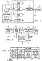
- FIGURE 1 is a block diagram of a hard disk drive system 10 according to the teachings of the present invention.
- Hard disk drive system 10 stores data during write operations and retrieves data during read operations.
- Hard disk drive system 10 includes hard disk drive integrated circuit 14, disk/head assembly 16, spindle motor 20, and motor driver system 22.
- Hard disk drive system 10 interfaces and exchanges data with a client 12 through bus 13. Hard disk drive system 10 receives data from client 12 and stores that data to disk/head assembly 16.
- Disk/head assembly 16 includes a number of rotating, magnetic platters. Electromagnetic heads store data to and retrieve data from circular tracks on the platters. A preamplifier (not explicitly shown) may be used to amplify the data signals as needed.
- Spindle motor 20 rotates the platters in disk/head assembly 16 at a constant angular speed while the electromagnetic heads read from or write to the circular tracks on the platters.
- Motor 20 may include a magnetic rotor that rotates in response to an electrical field created by the phase currents flowing through each of the three electric coils.
- Hard disk drive integrated circuit 14 processes the digital data exchanged between client 12 and disk/head assembly 16.
- Hard disk drive integrated circuit 14 includes disk control circuit 24, write channel 26, read channel 28, servo circuit 30, and motor control circuit 34.
- Write channel 26 processes any data that is to be stored to disk/head assembly 16. During write operations, write channel 26 receives a digital data signal from disk control circuit 24. Write channel 26 reformats and codes the digital data signal for storage and provides an analog data signal to disk/head assembly 16.
- Read channel 28 processes any data that is retrieved from disk/head assembly 16. During read operations, read channel 28 receives an analog data signal from disk/head assembly 16. Read channel 28 decodes and formats the analog data signal and provides a digital data signal to disk control circuit 24.
- Servo circuit 30 provides position error signals associated with positioning a head in disk/head assembly 16 to disk control circuit 24 during read and write operations.
- Servo circuit 30 receives a servo wedge signal from disk/head assembly 16.
- the servo wedge signal includes position error information.
- Servo circuit 20 processes this information and generates a servo output signal, which is received by disk control circuit 24.
- Disk control circuit 24 controls the various operations of hard disk drive system 10. Disk control circuit 24 receives data from client 12 through bus 13 and transmits a corresponding digital data signal to write channel 26. Disk control circuit 24 receives a digital data signal from read channel 28 and provides corresponding data to client 12 through bus 13. Disk control circuit 24 also receives position error information from servo circuit 30 in the form of a servo output signal. In response, disk control circuit 24 sends a motor control input signal to motor control circuit 34.
- Motor control circuit 34 comprises circuitry to properly interface with motor driver system 22 to control spindle motor 20.
- Motor control circuit 34 receives a motor control input signal from disk control circuit 24.
- Motor control circuit 34 processes the signal and sends a corresponding control signal to motor driver system 22.
- FIGURE 2 is a block diagram showing additional details of motor driver system 22 illustrated in FIGURE 1.
- Motor driver system 22 includes commutation state machine 40, phase voltage shaper 42, motor predriver and motor driver 44, sense resistor 45, and motor current amplitude control block 43.
- Motor driver system 22 produces three driving voltage signals 48, 50, and, 52.
- Driving voltage signals 48, 50, and 52 correspond to three electric coils in motor 20, and each driving voltage signal 48, 50, and 52 drives a separate one of the three coils in motor 20.
- motor driver system 22 generates sinusoidal phase currents in the electric coils of motor 29, reducing the acoustic noise emitted by motor 20.
- Phase voltage shaper 42 produces phase voltage signals 70, 72, and 74 that include hook-shaped waveforms.
- Motor predriver and motor driver 44 duplicates phase voltage signals 70, 72, and 74 to produce corresponding driving voltage signals 48, 50, and 52 that also include hook-shaped waveforms. Due to their hook-shaped waveforms, driving voltage signals 48, 50, and 52 generate sinusoidal phase currents in the electric coils of motor 20. These sinusoidal phase currents do not exhibit the abrupt transitions that plague some traditional motors. By eliminating the abrupt changes in the phase currents, the present invention reduces the harmonic content of the torque waveform associated with the phase currents. As a result, motor 20 emits less acoustic noise.
- Commutation state machine 40 connects to phase voltage shaper 42.
- Commutation state machine 40 generates digital signals that relate to the form of each phase voltage signal 70, 72, and 74.
- phase voltage shaper 42 From the digital signals received from commutation state machine 40, phase voltage shaper 42 generates three phase voltage signals 70, 72, and 74.
- phase voltage signals 70, 72, and 74 include hook-shaped waveforms.
- Phase voltage signals 70, 72, and 74 drive motor predriver and motor driver 44.
- Motor predriver and motor driver 44 duplicates phase voltage signals 70, 72, and 74 to produce corresponding driving voltage signals 48, 50, and 52.
- Phase voltage signal 70 corresponds to driving voltage signal 48, which drives a first electric coil in motor 20.
- Phase voltage signal 72 corresponds to driving voltage signal 50, which drives a second electric coil in motor 20.
- Phase voltage signal 74 corresponds to driving voltage signal 52, which drives a third electric coil in motor 20. Because driving voltage signals 48, 50, and 52 are amplified versions of phase voltage signals 70, 72, and 74, driving voltage signals 48, 50, and 52 also include hook-shaped waveforms.
- driving voltage signals 48, 50, and 52 Due to the hook-shaped waveforms included in driving voltages signals 48, 50, and 52, driving voltage signals 48, 50, and 52 generate a sinusoidal phase current in each electric coil. These sinusoidal phase currents do not exhibit the abrupt transitions that plague some traditional motors. By eliminating the abrupt changes in the phase currents, driving voltage signals 48, 50, and 52 reduce the harmonic content of the torque waveform associated with the phase currents. As a result, motor 20 emits less acoustic noise.
- motor current amplitude control block 43 controls the amplitude of the hook-shaped waveforms of phase voltage signals 70, 72, and 74.
- Current from motor 20 runs through sense resistor 45 and generates a voltage.
- Motor current amplitude control block 43 compares the voltage across sense resistor 45 to reference voltage 47 and generates an analog signal 41.
- Analog signal 41 is representative and proportional to the desired amplitude of the hook-shaped waveforms of phase voltage signals 70, 72, and 74.
- Phase voltage shaper 42 adjusts the amplitude of the hook-shaped waveforms of phase voltage signals 70, 72, and 74 in proportion to the change in amplitude of analog signal 41.
- motor current amplitude control block 43 affects the amplitude of the hook-shaped waveforms in driving voltage signals 48, 50, and 52. Changing the hook amplitude of driving voltage signals 48, 50, and 52 varies the motor current and thus the torque of motor 20.
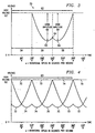
- FIGURE 3 is a graph over time of phase voltage signal 70 produced by phase voltage shaper 42, illustrating the hook-shaped waveforms included in phase voltage signal 70.
- phase voltage shaper 42 may produce a pulse-width modulated version of phase voltage signal 70.
- FIGURE 3 displays a continuous, linear version of phase voltage signal 70.
- Phase voltage signal 70 is periodic, and each period 60 is 360°.
- Phase voltage signal 70 comprises three waveforms 54, 56, and 58.
- Waveform 54 is a voltage held at a constant, high voltage 62 for about 120°.
- Waveform 56 is a voltage that "down hooks" for about 120°. Waveform 56 is referred to as a down hook voltage because waveform 56 is shaped like a hook and generally decreases in voltage with time. Waveform 56 decreases from high voltage 62 to low voltage 63 and then increases slightly to voltage 64. The difference in voltage between high voltage 62 and low voltage 63 is hook amplitude 66. In one embodiment, waveform 56 flows from high voltage 62 to voltage 64 as a function of (high voltage 62 - hook amplitude 66 * sin (wt - 120°)), where w is the rotational speed of motor 20 in degrees per second.
- Waveform 58 is a voltage that "up hooks" for about 120°. Waveform 58 is referred to as a up hook voltage because waveform 58 is shaped like a hook and generally increases in voltage with time. Waveform 58 decrease slightly from voltage 64 to low voltage 65 and then increases to high voltage 62. The difference in voltage between high voltage 62 and low voltage 65 is hook amplitude 68. In one embodiment, waveform 58 flows from voltage 64 to high voltage 62 as a function of (high voltage 62 - hook amplitude 68 * sin (wt-180°)), where w is the rotational speed of motor 20 in degrees per second.
- FIGURE 4 is a graph over time of all three phase voltage signals 70, 72, and 74 produced by phase voltage shaper 42, illustrating the phase differences between three phase voltage signals 70, 72, and 74.
- Phase voltage signals 72 and 74 share the same shape as phase voltage signal 70 of FIGURE 3.
- Phase voltage signals 70, 72, and 74 are displaced from one another by 120°.
- Phase voltage signal 70 leads phase voltage signal 72 by 120°
- phase voltage signal 70 leads phase voltage signal 74 by 240°.
- each of phase voltage signals 70, 72, and 74 comprise a separate one of three waveforms 54, 56, and 58.
- FIGURE 5 illustrates one embodiment of phase voltage shaper 42 that produces phase voltage signals 70, 72, and 74.
- FIGURE 5 is a block diagram of motor driver system 22 of FIGURE 2, showing additional details of one embodiment of phase voltage shaper 42.
- Phase voltage shaper 42 includes a sine hook wave generator 76, a pulse width modulator 78, and a multiplexer 80.
- Sine hook wave generator 76 receives digital signals from commutation state machine 40 and produces two hook waveforms, which are shown in FIGURES 6A and 6B.
- Pulse-width modulator 78 converts the two hook waveforms into pulse-width modulated, hook waveforms.
- multiplexer 80 receives the pulse-width modulated, hook waveforms and produces phase voltage signals 70, 72, and 74.
- FIGURES 6A and 6B are graphs over time of two hook waveforms 82 and 84 generated by sine hook wave generator 76.
- Phase voltage shaper 42 utilizes hook waveforms 82 and 84 to produce waveforms 58 and 56, shown in FIGURE 3.
- FIGURE 6A is a graph over time of hook waveform 82.
- Hook waveform 82 comprises a periodic, down hook voltage, and each period 83 is 120°.
- Hook waveform 82 corresponds to waveform 56 of FIGURE 3.
- FIGURE 6B is a graph over time of hook waveform 84.
- Hook waveform 84 comprises a periodic, up hook voltage, and each period 85 is 120°.
- Hook waveform 84 corresponds to waveform 58 of FIGURE 3.
- sine hook wave generator 76 utilizes linear, digital-to-analog converters to produce hook waveforms 82 and 84.
- Sine hook wave generator 76 connects to commutation state machine 40.
- Commutation state machine 40 generates digital signals that relate to the form of hook waveforms 82 and 84.
- phase voltage shaper 42 utilizes digital-to-analog converters to generate hook waveforms 82 and 84.
- the digital-to-analog converters function as a simple table-lookup block that produces quantized versions of the sine hook waveforms by approximating the exact hook waveforms 82 and 84.
- Pulse-width modulator 78 converts hook waveforms 82 and 84 into pulse-width modulated, hook waveforms.
- the pulse-width modulated, hook waveforms comprise two voltages, a high voltage and a low voltage.
- the pulse-width modulated, hook waveforms alternate between the high voltage and the low voltage.
- each pulse-width modulated waveform alternates between the high voltage and the low voltage such that the weighted average of the voltages over any small interval of time equals the voltage of corresponding waveform 82 or 84 at that point in time.
- the pulse-width modulated, hook waveforms When applied to the power switching devices in motor predriver and motor driver 44, the pulse-width modulated, hook waveforms generally dissipate less power than the linear versions of hook waveforms 82 and 84.
- FIGURE 7 is a table illustrating the sequences in which multiplexer 80 may combine hook waveforms 82 and 84, shown in FIGURE 6A and 6B, and a high voltage signal to produce phase voltage signals 70, 72, and 74, shown in FIGURE 4.
- Multiplexer 80 receives control signals from commutation state machine 40. At any given time, multiplexer 80 connects each of the high voltage signal, hook waveform 82, and hook waveform 84 to a separate phase voltage signal 70, 72, and 74 for about 120°.
- FIGURE 7 demonstrates over one period of 360° a sequence that multiplexer 80 may use to produce phase voltage signals 70, 72, and 74.
- multiplexer 80 can produce each period of phase voltage signals 70, 72, and 74 by combining the high voltage for about 120°, down hook waveform 82 for about 120°, and up hook waveform 84 for about 120°.
- motor driver system 22 generates sinusoidal phase currents in the electric coils of motor 29, reducing the acoustic noise emitted by motor 20. Due to their hook-shaped waveforms, driving voltages 48, 50, and 52 generate sinusoidal phase currents in the electric coils. By eliminating the abrupt changes in the phase currents, the present invention reduces the harmonic content of the torque waveform associated with the phase currents and reduces the related acoustic noise emitted by motor 20.
Description
- This invention relates generally to the field of electric motor driving systems and, more particularly, to a method and apparatus for driving a three-phase motor to reduce acoustic noise in a mass storage device.
- A mass storage device, such as a hard disk drive, utilizes a spindle motor to rotate platters that store information. The spindle motor generally rotates the platters at a constant angular speed while electromagnetic heads read from or write to circular tracks on the platters. The spindle motor is often implemented as a three phase motor.
- A typical, three-phase motor includes a magnetic rotor and three electric coils. The three electric coils are related to the three phases of the motor. A separate current, called a phase current, flows through each of the three electric coils of the motor. The rotor rotates in response to an electrical field created by the phase currents.
- The phase currents flowing through the three electric coils generally interact with the magnetic elements in the motor to produce acoustic noise. In some traditional drives, each of the motor's three electric coils cycles through three states: each electric coil can be held at ground, driven to some positive voltage, or floated. As a result, the phase currents flowing through the electric coils have very abrupt transitions. Because torque is proportional to current, the abrupt changes in the phase currents cause the torque also to change abruptly. If the harmonics in the torque waveform excite mechanical resonances, the motor structure may vibrate and generate audible noise.
- US patent application no. 4651067 describes an apparatus for driving a brushless motor in which a ripple appearing in the rotation torque of the motor is cancelled by driving the motor with a signal current. In order to obtain such a signal current, counter-electromotive forces induced in the stator coils of the motor are detected, and the level of the signal indicative of the detected counter-electromotive forces is controlled depending on the load and rotation speed of the motor to provide a control signal for controlling the motor drive current.
- US patent application no. 5300873 describes a motor control apparatus for rotating a motor smoothly. A sine wave form which is an ideal wave form of a signal is stored, and the motor is driven by a signal having the ideal wave form obtained by correcting the period and phase of the stored sine wave form. A comparator receives a detection signal ..which indicates the rotating state of the motor through an A/D converter, and obtains the correction values of the current period and phase. A wave form setting means corrects the set period and phase, generates a sine wave having the corrected period and phase on the basis of the sine wave data stored in a sine wave data region, and outputs a driving signal having the sine wave form through a D/A converter.
- European patent application, publication no. 0831580 describes an apparatus for controlling the driving current for the speed a motor.
- European patent application, publication no. 0776007 describes information storing apparatus having a spindle motor for driving a recording disk. Whether the information storing apparatus is in a read mode or seek mode is detected, and the electrical input to the motor is accordingly changed between read mode and the seek mode to achieve power savings, low noise and vibrations.
- Accordingly, a need has arisen for an improved method and system for driving a three-phase motor. The present invention provides a method and system for driving a three-phase motor and a hard disk drive system incorporating the same that address the shortcomings of prior systems and methods and.
- According to one embodiment of the invention, a method of driving an electric motor includes generating a periodic, driving voltage. The driving voltage comprises a sequence of first, second, and third waveforms. The first waveform in the sequence is a generally constant, high voltage. The second waveform in the sequence is a down hook voltage. The third waveform in the sequence is an up hook voltage. The method also includes applying the driving voltage to a coil of the motor to generate a generally sinusoidal current through the coil of the motor.
- According to another embodiment of the invention, a hard disk drive system includes a disk storage media operable to store information and a spindle motor operable to rotate the disk storage media. The hard disk drive system also includes a motor driver. The motor driver is operable to apply a periodic, driving voltage to a coil of the motor to generate a generally sinusoidal current through the coil. The driving voltage comprises a sequence of first, second, and third waveforms. The first waveform in the sequence is a generally constant, high voltage The second waveform in the sequence is a down hook voltage. The third waveform in the sequence is an up hook voltage.
- Embodiments of the invention provide numerous technical advantages. For example, one embodiment of the invention drives each of three electric coils of a motor with a voltage that includes waveforms in the shape of a hook. These driving voltages with the hook-shaped waveforms generate sinusoidal phase currents in the electric coils of the motor. The sinusoidal phase currents do not exhibit the abrupt transitions that plague some traditional motors. Thus, the sinusoidal phase currents reduce the harmonics of the torque waveform generated by changes in the phase currents. As a result, the motor exhibits less acoustic noise.
- For a more complete understanding of the present invention and the advantages thereof, reference is now made to the following descriptions taken in connection with the accompanying drawings in which:
- FIGURE 1 is a block diagram of a hard disk drive system according to the teachings of the present invention;
- FIGURE 2 is a block diagram of a motor driver system of the hard disk drive system shown in FIGURE 1;
- FIGURE 3 is a graph over time of a phase voltage signal produced by a phase voltage shaper shown in FIGURE 2, illustrating the hook-shaped waveforms included in phase voltage signals;
- FIGURE 4 is a graph over time of all three phase voltage signals produced by the phase voltage shaper shown in FIGURE 2, illustrating the phase differences between the three phase voltage signals;
- FIGURE 5 is a block diagram of the motor driver system of FIGURE 2, providing additional details of one embodiment of the phase voltage shaper;
- FIGURES 6A and 6B are graphs over time of the two hook waveforms generated by the sine hook wave generator shown in FIGURE 5; and
- FIGURE 7 is a table illustrating the sequences in which the multiplexer shown in FIGURE 5 may combine the two hook waveforms of FIGURE 6 and a high voltage signal to produce the phase voltage signals of FIGURE 4.
- The present invention and its advantages are best understood by referring to FIGURES 1 through 7 of the drawings, like numerals being used for like and corresponding parts of the various drawings.
- FIGURE 1 is a block diagram of a hard
disk drive system 10 according to the teachings of the present invention. Harddisk drive system 10 stores data during write operations and retrieves data during read operations. Harddisk drive system 10 includes hard disk driveintegrated circuit 14, disk/head assembly 16,spindle motor 20, andmotor driver system 22. - Hard
disk drive system 10 interfaces and exchanges data with aclient 12 throughbus 13. Harddisk drive system 10 receives data fromclient 12 and stores that data to disk/head assembly 16. - Later, hard
disk drive system 10 can retrieve the data from disk/head assembly 16 and provide that data back toclient 12. Disk/head assembly 16 includes a number of rotating, magnetic platters. Electromagnetic heads store data to and retrieve data from circular tracks on the platters. A preamplifier (not explicitly shown) may be used to amplify the data signals as needed. -
Spindle motor 20 rotates the platters in disk/head assembly 16 at a constant angular speed while the electromagnetic heads read from or write to the circular tracks on the platters.Motor 20 may include a magnetic rotor that rotates in response to an electrical field created by the phase currents flowing through each of the three electric coils. - Hard disk drive integrated
circuit 14 processes the digital data exchanged betweenclient 12 and disk/head assembly 16. Hard disk drive integratedcircuit 14 includesdisk control circuit 24, writechannel 26, readchannel 28,servo circuit 30, andmotor control circuit 34. Writechannel 26 processes any data that is to be stored to disk/head assembly 16. During write operations, writechannel 26 receives a digital data signal fromdisk control circuit 24. Writechannel 26 reformats and codes the digital data signal for storage and provides an analog data signal to disk/head assembly 16. - Read
channel 28 processes any data that is retrieved from disk/head assembly 16. During read operations, readchannel 28 receives an analog data signal from disk/head assembly 16. Readchannel 28 decodes and formats the analog data signal and provides a digital data signal todisk control circuit 24. -
Servo circuit 30 provides position error signals associated with positioning a head in disk/head assembly 16 todisk control circuit 24 during read and write operations.Servo circuit 30 receives a servo wedge signal from disk/head assembly 16. The servo wedge signal includes position error information.Servo circuit 20 processes this information and generates a servo output signal, which is received bydisk control circuit 24. -
Disk control circuit 24 controls the various operations of harddisk drive system 10.Disk control circuit 24 receives data fromclient 12 throughbus 13 and transmits a corresponding digital data signal to writechannel 26.Disk control circuit 24 receives a digital data signal from readchannel 28 and provides corresponding data toclient 12 throughbus 13.Disk control circuit 24 also receives position error information fromservo circuit 30 in the form of a servo output signal. In response,disk control circuit 24 sends a motor control input signal tomotor control circuit 34. -
Motor control circuit 34 comprises circuitry to properly interface withmotor driver system 22 to controlspindle motor 20.Motor control circuit 34 receives a motor control input signal fromdisk control circuit 24.Motor control circuit 34 processes the signal and sends a corresponding control signal tomotor driver system 22. - FIGURE 2 is a block diagram showing additional details of
motor driver system 22 illustrated in FIGURE 1.Motor driver system 22 includescommutation state machine 40,phase voltage shaper 42, motor predriver andmotor driver 44,sense resistor 45, and motor currentamplitude control block 43.Motor driver system 22 produces three drivingvoltage signals motor 20, and each drivingvoltage signal motor 20. - According to the teachings of the present invention,
motor driver system 22 generates sinusoidal phase currents in the electric coils of motor 29, reducing the acoustic noise emitted bymotor 20.Phase voltage shaper 42 produces phase voltage signals 70, 72, and 74 that include hook-shaped waveforms. Motor predriver andmotor driver 44 duplicates phase voltage signals 70, 72, and 74 to produce corresponding drivingvoltage signals voltage signals motor 20. These sinusoidal phase currents do not exhibit the abrupt transitions that plague some traditional motors. By eliminating the abrupt changes in the phase currents, the present invention reduces the harmonic content of the torque waveform associated with the phase currents. As a result,motor 20 emits less acoustic noise. -
Commutation state machine 40 connects to phasevoltage shaper 42.Commutation state machine 40 generates digital signals that relate to the form of eachphase voltage signal commutation state machine 40,phase voltage shaper 42 generates three phase voltage signals 70, 72, and 74. As further explained below, phase voltage signals 70, 72, and 74 include hook-shaped waveforms. - Phase voltage signals 70, 72, and 74 drive motor predriver and
motor driver 44. Motor predriver andmotor driver 44 duplicates phase voltage signals 70, 72, and 74 to produce corresponding drivingvoltage signals Phase voltage signal 70 corresponds to drivingvoltage signal 48, which drives a first electric coil inmotor 20.Phase voltage signal 72 corresponds to drivingvoltage signal 50, which drives a second electric coil inmotor 20.Phase voltage signal 74 corresponds to drivingvoltage signal 52, which drives a third electric coil inmotor 20. Because drivingvoltage signals voltage signals - Due to the hook-shaped waveforms included in driving voltages signals 48, 50, and 52, driving
voltage signals voltage signals motor 20 emits less acoustic noise. - In the illustrated embodiment, motor current
amplitude control block 43 controls the amplitude of the hook-shaped waveforms of phase voltage signals 70, 72, and 74. Current frommotor 20 runs throughsense resistor 45 and generates a voltage. Motor currentamplitude control block 43 compares the voltage acrosssense resistor 45 toreference voltage 47 and generates ananalog signal 41.Analog signal 41 is representative and proportional to the desired amplitude of the hook-shaped waveforms of phase voltage signals 70, 72, and 74.Phase voltage shaper 42 adjusts the amplitude of the hook-shaped waveforms of phase voltage signals 70, 72, and 74 in proportion to the change in amplitude ofanalog signal 41. Because drivingvoltage signals amplitude control block 43 affects the amplitude of the hook-shaped waveforms in drivingvoltage signals voltage signals motor 20. - FIGURE 3 is a graph over time of
phase voltage signal 70 produced byphase voltage shaper 42, illustrating the hook-shaped waveforms included inphase voltage signal 70. As described in more detail below,phase voltage shaper 42 may produce a pulse-width modulated version ofphase voltage signal 70. For the purpose of clarity, FIGURE 3 displays a continuous, linear version ofphase voltage signal 70.Phase voltage signal 70 is periodic, and eachperiod 60 is 360°.Phase voltage signal 70 comprises threewaveforms -
Waveform 54 is a voltage held at a constant,high voltage 62 for about 120°. -
Waveform 56 is a voltage that "down hooks" for about 120°.Waveform 56 is referred to as a down hook voltage becausewaveform 56 is shaped like a hook and generally decreases in voltage with time.Waveform 56 decreases fromhigh voltage 62 tolow voltage 63 and then increases slightly to voltage 64. The difference in voltage betweenhigh voltage 62 andlow voltage 63 ishook amplitude 66. In one embodiment,waveform 56 flows fromhigh voltage 62 to voltage 64 as a function of (high voltage 62 -hook amplitude 66 * sin (wt - 120°)), where w is the rotational speed ofmotor 20 in degrees per second. -
Waveform 58 is a voltage that "up hooks" for about 120°.Waveform 58 is referred to as a up hook voltage becausewaveform 58 is shaped like a hook and generally increases in voltage with time.Waveform 58 decrease slightly from voltage 64 tolow voltage 65 and then increases tohigh voltage 62. The difference in voltage betweenhigh voltage 62 andlow voltage 65 ishook amplitude 68. In one embodiment,waveform 58 flows from voltage 64 tohigh voltage 62 as a function of (high voltage 62 -hook amplitude 68 * sin (wt-180°)), where w is the rotational speed ofmotor 20 in degrees per second. - FIGURE 4 is a graph over time of all three phase voltage signals 70, 72, and 74 produced by
phase voltage shaper 42, illustrating the phase differences between three phase voltage signals 70, 72, and 74. Phase voltage signals 72 and 74 share the same shape asphase voltage signal 70 of FIGURE 3. Phase voltage signals 70, 72, and 74, however, are displaced from one another by 120°.Phase voltage signal 70 leadsphase voltage signal 72 by 120°, andphase voltage signal 70 leadsphase voltage signal 74 by 240°. Thus, at any given time, each of phase voltage signals 70, 72, and 74 comprise a separate one of threewaveforms phase voltage shaper 42 that produces phase voltage signals 70, 72, and 74. - FIGURE 5 is a block diagram of
motor driver system 22 of FIGURE 2, showing additional details of one embodiment ofphase voltage shaper 42.Phase voltage shaper 42 includes a sinehook wave generator 76, apulse width modulator 78, and amultiplexer 80. Sinehook wave generator 76 receives digital signals fromcommutation state machine 40 and produces two hook waveforms, which are shown in FIGURES 6A and 6B. Pulse-width modulator 78 converts the two hook waveforms into pulse-width modulated, hook waveforms. As explained in conjunction with FIGURE 7,multiplexer 80 receives the pulse-width modulated, hook waveforms and produces phase voltage signals 70, 72, and 74. - FIGURES 6A and 6B are graphs over time of two
hook waveforms hook wave generator 76.Phase voltage shaper 42 utilizeshook waveforms waveforms hook waveform 82.Hook waveform 82 comprises a periodic, down hook voltage, and eachperiod 83 is 120°.Hook waveform 82 corresponds to waveform 56 of FIGURE 3. FIGURE 6B is a graph over time ofhook waveform 84.Hook waveform 84 comprises a periodic, up hook voltage, and eachperiod 85 is 120°.Hook waveform 84 corresponds to waveform 58 of FIGURE 3. - In one embodiment, sine
hook wave generator 76 utilizes linear, digital-to-analog converters to producehook waveforms hook wave generator 76 connects tocommutation state machine 40.Commutation state machine 40 generates digital signals that relate to the form ofhook waveforms commutation state machine 40,phase voltage shaper 42 utilizes digital-to-analog converters to generatehook waveforms exact hook waveforms - Pulse-
width modulator 78converts hook waveforms hook waveforms waveform motor driver 44, the pulse-width modulated, hook waveforms generally dissipate less power than the linear versions ofhook waveforms - FIGURE 7 is a table illustrating the sequences in which multiplexer 80 may combine
hook waveforms Multiplexer 80 receives control signals fromcommutation state machine 40. At any given time,multiplexer 80 connects each of the high voltage signal,hook waveform 82, andhook waveform 84 to a separatephase voltage signal multiplexer 80 can produce each period of phase voltage signals 70, 72, and 74 by combining the high voltage for about 120°, downhook waveform 82 for about 120°, and uphook waveform 84 for about 120°. - According to the teachings of the present invention,
motor driver system 22 generates sinusoidal phase currents in the electric coils of motor 29, reducing the acoustic noise emitted bymotor 20. Due to their hook-shaped waveforms, drivingvoltages motor 20. - Although the present invention and its advantages are described in detail, a person skilled in the art could make various alterations, substitutions, and omissions without departing from the scope of the present invention as defined by the appended claims.
Claims (14)
- A method of driving an electric motor (20), the method comprising:generating a driving voltage;applying the driving voltage to a coil of the motor to generate a generally sinusoidal current through the coil of the motor; and
characterized by
the driving voltage being periodic and comprising a sequence of first, second, and third waveforms, the first waveform (54) in the sequence being a generally constant, high voltage, the second waveform (56) in the sequence being a down hook voltage, and the third waveform (58) in the sequence being an up hook voltage. - The method of Claim 1, wherein generating a periodic, driving voltage comprises generating a driving voltage having a period of 360° and a hook amplitude, the period comprising a sequence of first, second, and third waveforms, the first waveform (54) being a generally constant, high voltage for about 120°, the second waveform (56) being a voltage that decreases from the high voltage to a lower voltage generally as a function of (the high voltage - the hook amplitude * sin(wt-120°)) for about 120°; and the third waveform (58) being a voltage that increases from the lower voltage to the high voltage generally as a function of (the high voltage - the hook amplitude * sin(wt-180°)) for about 120°.
- The method of Claim 1, further comprising:generating a phase voltage (70) by a phase voltage shaper (42), the phase voltage comprising a sequence of first, second, and third waveforms, the first waveform (54) in the sequence being a generally constant, high voltage, the second waveform (56) in the sequence being a down hook voltage, and the third waveform (58) in the sequence being an up hook voltage; anddriving a motor driver (44) with the phase voltage to generate the driving voltage.
- The method of Claim 1, further comprising:generating two periodic, hook waveforms (82, 84) with a sine hook wave generator (76), each hook waveform comprising of a down hook voltage and an up hook voltage;switching alternatively between each of the two hook waveforms (82, 84) and a generally constant, high voltage to generate a phase voltage (70), the phase voltage comprising a sequence of first, second, and third waveforms, the first waveform (54) in the sequence being a generally constant, high voltage, the second waveform (56) in the sequence being a down hook voltage, and the third waveform (58) in the sequence being a up hook voltage; anddriving a motor driver (44) with the phase voltage to produce the driving voltage.
- The method of Claim 3, wherein generating a phase voltage comprises generating a phase voltage that is pulse-width modulated.
- The method of Claim 3, wherein generating a phase voltage comprises generating a phase voltage by a phase voltage shaper (42) having at least one digital-to-analog converter.
- A method of driving a three-phase motor according to any of the preceding claims wherein the steps recited in Claim 1 are carried out in respect of each of three coils of the motor (20) such that, three periodic driving voltages (48, 50, 52) are generated and each applied to a separate one of the three coils of the motor, and, at any given time, each of the three coils is being driven by a separate one of the first, second, and third waveforms (54, 56, 58).
- A hard disk drive system (10) comprising:a disk storage media operable to store information;a spindle motor (20) operable to rotate the disk storage media; and characterized by:a motor driver (22) operable to apply a periodic, driving voltage to a coil of the motor to generate a generally sinusoidal current through the coil, the driving voltage comprising a sequence of first, second, and third waveforms, the first waveform (54) in the sequence being a generally constant, high voltage, the second waveform (56) in the sequence being a down hook voltage, and the third waveform (58) in the sequence being an up hook voltage.
- The hard disk drive system of Claim 8, wherein:the driving voltage has a period of 360° and a hook amplitude;the first waveform (54) is a generally constant, high voltage for about 120°;the second waveform (56) is a voltage that decreases from the high voltage to a lower voltage generally as a function of (the high voltage - the hook amplitude * sin (wt-120°)) for about 120°; andthe third waveform (58) is a voltage that increases from the lower voltage to the high voltage generally as a function of (the high voltage - the hook amplitude * sin(wt-180°)) for about 120°.
- The hard disk drive system of Claim 8, further comprising a phase voltage shaper (42) operable to generate a phase voltage (70) that drives the motor driver (44), the phase voltage comprising of a sequence of first, second, and third waveforms, the first waveform (54) in the sequence being a generally constant, high voltage, the second waveform (56) in the sequence being a down hook voltage, and the third waveform (58) in the sequence being an up hook voltage.
- The hard disk drive system of Claim 8, further comprising:a sine hook wave generator (76) operable to generate two periodic, hook waveforms (82, 84), each hook waveform comprising a down.hook voltage and a up hook voltage; anda multiplexer (80) operable to switch alternatively between each of the two hook waveforms and a generally constant, high voltage to generate a phase voltage (70) that drives the motor driver (44), the phase voltage comprising of a sequence of first, second, and third waveforms, the first waveform (54) in the sequence being a generally constant, high voltage, the second waveform (56) in the sequence being a down hook voltage, and the third waveform (58) in the sequence being an up hook voltage.
- The hard disk drive system of Claim 10, wherein the phase voltage is pulse-width modulated.
- The hard disk drive system of Claim 10, wherein the phase voltage shaper (42) comprises at least one digital-to-analog converter.
- A hard disk drive system according to any of Claims 8 to 13, operable for driving a three-phase motor, wherein the motor driver (44) is operable to apply three periodic driving voltages (48, 50, 52), each to a separate one of the three coils of the motor, such that, at any given time, each of the three coils is being driven by a separate one of the first, second, and third waveforms (54, 56, 58).
Applications Claiming Priority (2)
| Application Number | Priority Date | Filing Date | Title |
|---|---|---|---|
| US196788 | 1998-11-20 | ||
| US09/196,788 US6008611A (en) | 1998-11-20 | 1998-11-20 | Method and system for driving a three-phase motor in a mass storage device |
Publications (3)
| Publication Number | Publication Date |
|---|---|
| EP1003275A2 EP1003275A2 (en) | 2000-05-24 |
| EP1003275A3 EP1003275A3 (en) | 2002-11-27 |
| EP1003275B1 true EP1003275B1 (en) | 2006-03-01 |
Family
ID=22726803
Family Applications (1)
| Application Number | Title | Priority Date | Filing Date |
|---|---|---|---|
| EP99203864A Expired - Lifetime EP1003275B1 (en) | 1998-11-20 | 1999-11-19 | Method and system for driving a three-phase motor in a mass storage device |
Country Status (6)
| Country | Link |
|---|---|
| US (1) | US6008611A (en) |
| EP (1) | EP1003275B1 (en) |
| JP (1) | JP2000166280A (en) |
| KR (1) | KR100755090B1 (en) |
| DE (1) | DE69930056T2 (en) |
| TW (1) | TW488127B (en) |
Families Citing this family (5)
| Publication number | Priority date | Publication date | Assignee | Title |
|---|---|---|---|---|
| KR100413306B1 (en) * | 2000-10-18 | 2003-12-31 | 이석균 | Length varying device for pedal arms of bicycle |
| JP4647136B2 (en) * | 2001-05-31 | 2011-03-09 | ルネサスエレクトロニクス株式会社 | Magnetic disk storage device |
| US7265516B2 (en) * | 2001-12-13 | 2007-09-04 | Lacroix Michael Charles | Linear electric motor controller and system for providing linear control |
| US9003209B2 (en) | 2012-06-29 | 2015-04-07 | Intel Corporation | Efficient integrated switching voltage regulator comprising switches coupled to bridge drivers to provide regulated power supply to power domains |
| TWI727705B (en) * | 2020-03-17 | 2021-05-11 | 立錡科技股份有限公司 | Power supply controller having reduced acoustic noise and method of reducing acoustic noise |
Family Cites Families (14)
| Publication number | Priority date | Publication date | Assignee | Title |
|---|---|---|---|---|
| US4651067A (en) * | 1984-02-24 | 1987-03-17 | Hitachi, Ltd. | Apparatus for driving brushless motor |
| JPH05137382A (en) * | 1991-11-07 | 1993-06-01 | Rohm Co Ltd | Motor controller |
| JP3081947B2 (en) * | 1992-01-10 | 2000-08-28 | ローム株式会社 | Motor control circuit and motor driving device using the same |
| US5616994A (en) * | 1994-01-12 | 1997-04-01 | Mitsubishi Denki Kabushiki Kaisha | Drive circuit for brushless motor |
| EP0707378B1 (en) * | 1994-03-31 | 2001-11-21 | Daikin Industries, Limited | Method of controlling driving of brushless dc motor, and apparatus therefor, and electric machinery and apparatus used therefor |
| DE4432530A1 (en) * | 1994-09-13 | 1996-03-14 | Bosch Gmbh Robert | Circuit and method for driving a brushless DC motor |
| JP3403283B2 (en) * | 1995-11-24 | 2003-05-06 | ミネベア株式会社 | Information storage device |
| DE59709336D1 (en) * | 1996-09-21 | 2003-03-27 | Diehl Ako Stiftung Gmbh & Co | Device for driving current control of an electrically commutated permanent magnet motor |
| JP3281561B2 (en) * | 1996-12-25 | 2002-05-13 | シャープ株式会社 | Motor speed control device |
| KR19980054931A (en) * | 1996-12-27 | 1998-09-25 | 김영환 | Error correction device of multimedia equipment |
| US5777449A (en) * | 1996-12-31 | 1998-07-07 | Sgs-Thomson Microelectronics, Inc. | Torque ripple reduction using back-emf feedback |
| JPH10290593A (en) * | 1997-04-15 | 1998-10-27 | Mitsubishi Electric Corp | Drive circuit for sensorless brushless motor |
| US5883479A (en) * | 1997-07-01 | 1999-03-16 | Stmicroelectronics, Inc. | BEMF rectification during power off to prevent parasitic effect |
| JPH11285287A (en) * | 1998-03-27 | 1999-10-15 | Mitsubishi Electric Corp | Polyphase motor-drive circuit |
-
1998
- 1998-11-20 US US09/196,788 patent/US6008611A/en not_active Expired - Lifetime
-
1999
- 1999-11-19 DE DE69930056T patent/DE69930056T2/en not_active Expired - Lifetime
- 1999-11-19 EP EP99203864A patent/EP1003275B1/en not_active Expired - Lifetime
- 1999-11-19 KR KR1019990051449A patent/KR100755090B1/en active IP Right Grant
- 1999-11-22 JP JP11331587A patent/JP2000166280A/en not_active Abandoned
-
2000
- 2000-02-03 TW TW088120314A patent/TW488127B/en not_active IP Right Cessation
Also Published As
| Publication number | Publication date |
|---|---|
| TW488127B (en) | 2002-05-21 |
| DE69930056T2 (en) | 2006-10-26 |
| US6008611A (en) | 1999-12-28 |
| EP1003275A3 (en) | 2002-11-27 |
| EP1003275A2 (en) | 2000-05-24 |
| KR100755090B1 (en) | 2007-09-04 |
| KR20000035572A (en) | 2000-06-26 |
| JP2000166280A (en) | 2000-06-16 |
| DE69930056D1 (en) | 2006-04-27 |
Similar Documents
| Publication | Publication Date | Title |
|---|---|---|
| US6972539B1 (en) | Disk drive employing commutation phase modulation and current modulation of a spindle motor | |
| US6236174B1 (en) | Method and apparatus for driving a polyphase, brushless DC motor | |
| US5798623A (en) | Switch mode sine wave driver for polyphase brushless permanent magnet motor | |
| US7723937B2 (en) | Drive control device of motor and a method of start-up | |
| US6252362B1 (en) | Method and apparatus for synchronizing PWM sinusoidal drive to a DC motor | |
| US9431934B2 (en) | Motor controller with drive-signal conditioning | |
| US7750586B2 (en) | Drive control device of motor and a method of start-up | |
| US5530326A (en) | Brushless DC spindle motor startup control | |
| JP4877764B2 (en) | Motor drive circuit, method and disk device using them | |
| JP5129529B2 (en) | Motor drive device and motor rotation control method | |
| US5977737A (en) | Digital motor driver circuit and method | |
| US6498446B1 (en) | System and method for optimizing torque in a polyphase disk drive motor | |
| US5898283A (en) | Voltage feedforward control system for a spindle motor of a disk drive | |
| EP1003275B1 (en) | Method and system for driving a three-phase motor in a mass storage device | |
| US20020027423A1 (en) | Method and circuit for driving a brushless dc motor to reduce low acoustic noise | |
| JP3958819B2 (en) | Method of driving a two-phase claw pole type stepping motor used in a recording disk driving device of an information storage device | |
| JP4896568B2 (en) | Motor drive circuit, method and disk device using them | |
| JP2002010673A (en) | Silent spin sine wave generator | |
| JP2001186788A (en) | Drive circuit of brushless motor |
Legal Events
| Date | Code | Title | Description |
|---|---|---|---|
| PUAI | Public reference made under article 153(3) epc to a published international application that has entered the european phase |
Free format text: ORIGINAL CODE: 0009012 |
|
| AK | Designated contracting states |
Kind code of ref document: A2 Designated state(s): AT BE CH CY DE DK ES FI FR GB GR IE IT LI LU MC NL PT SE |
|
| AX | Request for extension of the european patent |
Free format text: AL;LT;LV;MK;RO;SI |
|
| PUAL | Search report despatched |
Free format text: ORIGINAL CODE: 0009013 |
|
| AK | Designated contracting states |
Kind code of ref document: A3 Designated state(s): AT BE CH CY DE DK ES FI FR GB GR IE IT LI LU MC NL PT SE |
|
| AX | Request for extension of the european patent |
Free format text: AL;LT;LV;MK;RO;SI |
|
| 17P | Request for examination filed |
Effective date: 20030527 |
|
| AKX | Designation fees paid |
Designated state(s): DE FR GB |
|
| 17Q | First examination report despatched |
Effective date: 20031107 |
|
| GRAP | Despatch of communication of intention to grant a patent |
Free format text: ORIGINAL CODE: EPIDOSNIGR1 |
|
| GRAS | Grant fee paid |
Free format text: ORIGINAL CODE: EPIDOSNIGR3 |
|
| GRAA | (expected) grant |
Free format text: ORIGINAL CODE: 0009210 |
|
| AK | Designated contracting states |
Kind code of ref document: B1 Designated state(s): DE FR GB |
|
| REG | Reference to a national code |
Ref country code: GB Ref legal event code: FG4D |
|
| REF | Corresponds to: |
Ref document number: 69930056 Country of ref document: DE Date of ref document: 20060427 Kind code of ref document: P |
|
| ET | Fr: translation filed | ||
| PLBE | No opposition filed within time limit |
Free format text: ORIGINAL CODE: 0009261 |
|
| STAA | Information on the status of an ep patent application or granted ep patent |
Free format text: STATUS: NO OPPOSITION FILED WITHIN TIME LIMIT |
|
| 26N | No opposition filed |
Effective date: 20061204 |
|
| PGFP | Annual fee paid to national office [announced via postgrant information from national office to epo] |
Ref country code: GB Payment date: 20141027 Year of fee payment: 16 Ref country code: DE Payment date: 20141201 Year of fee payment: 16 Ref country code: FR Payment date: 20141027 Year of fee payment: 16 |
|
| REG | Reference to a national code |
Ref country code: DE Ref legal event code: R119 Ref document number: 69930056 Country of ref document: DE |
|
| GBPC | Gb: european patent ceased through non-payment of renewal fee |
Effective date: 20151119 |
|
| REG | Reference to a national code |
Ref country code: FR Ref legal event code: ST Effective date: 20160729 |
|
| PG25 | Lapsed in a contracting state [announced via postgrant information from national office to epo] |
Ref country code: GB Free format text: LAPSE BECAUSE OF NON-PAYMENT OF DUE FEES Effective date: 20151119 Ref country code: DE Free format text: LAPSE BECAUSE OF NON-PAYMENT OF DUE FEES Effective date: 20160601 |
|
| PG25 | Lapsed in a contracting state [announced via postgrant information from national office to epo] |
Ref country code: FR Free format text: LAPSE BECAUSE OF NON-PAYMENT OF DUE FEES Effective date: 20151130 |