EP1002933A2 - Hydraulicher Bohrlochdruckgenerator - Google Patents
Hydraulicher Bohrlochdruckgenerator Download PDFInfo
- Publication number
- EP1002933A2 EP1002933A2 EP99307942A EP99307942A EP1002933A2 EP 1002933 A2 EP1002933 A2 EP 1002933A2 EP 99307942 A EP99307942 A EP 99307942A EP 99307942 A EP99307942 A EP 99307942A EP 1002933 A2 EP1002933 A2 EP 1002933A2
- Authority
- EP
- European Patent Office
- Prior art keywords
- hydraulic pressure
- chamber
- pressure generator
- fluid
- well
- Prior art date
- Legal status (The legal status is an assumption and is not a legal conclusion. Google has not performed a legal analysis and makes no representation as to the accuracy of the status listed.)
- Withdrawn
Links
Images


Classifications
-
- E—FIXED CONSTRUCTIONS
- E21—EARTH OR ROCK DRILLING; MINING
- E21B—EARTH OR ROCK DRILLING; OBTAINING OIL, GAS, WATER, SOLUBLE OR MELTABLE MATERIALS OR A SLURRY OF MINERALS FROM WELLS
- E21B33/00—Sealing or packing boreholes or wells
- E21B33/10—Sealing or packing boreholes or wells in the borehole
- E21B33/12—Packers; Plugs
- E21B33/128—Packers; Plugs with a member expanded radially by axial pressure
- E21B33/1285—Packers; Plugs with a member expanded radially by axial pressure by fluid pressure
-
- E—FIXED CONSTRUCTIONS
- E21—EARTH OR ROCK DRILLING; MINING
- E21B—EARTH OR ROCK DRILLING; OBTAINING OIL, GAS, WATER, SOLUBLE OR MELTABLE MATERIALS OR A SLURRY OF MINERALS FROM WELLS
- E21B23/00—Apparatus for displacing, setting, locking, releasing or removing tools, packers or the like in boreholes or wells
- E21B23/06—Apparatus for displacing, setting, locking, releasing or removing tools, packers or the like in boreholes or wells for setting packers
Definitions
- the present invention relates generally to operations performed in subterranean wells and, in an embodiment described herein, more particularly provides a hydraulic pressure generator.
- a sliding sleeve valve may be opened and/or closed by applying fluid pressure to a tubing string, or a packer may be set or unset by applying fluid pressure within the packer mandrel.
- a packer may be set or unset by applying fluid pressure within the packer mandrel.
- fluid pressure is typically applied to a tubing string at the earth's surface, or the fluid pressure is applied to an annulus between the tubing string and the wellbore.
- fluid pressure is typically applied to a tubing string at the earth's surface, or the fluid pressure is applied to an annulus between the tubing string and the wellbore.
- the tubing string or annulus may have a leak, or there may be other tools in the well which would be undesirably actuated by the application of fluid pressure thereto.
- actuation of the well tool may require application of greater fluid pressure to the well tool than the tubing string or casing may safely withstand.
- an apparatus which permits actuation of a well tool by application of fluid pressure to the well tool downhole.
- a hydraulic pressure generator utilizes well fluid pressure to generate an elevated fluid pressure for actuation of the well tool.
- an apparatus which includes a hydraulic pressure generator operatively interconnected to a well tool.
- the hydraulic pressure generator is actuated by selectively causing a barrier device to permit communication between well fluid pressure and a chamber within the hydraulic pressure generator.
- barrier devices including a valve, a frangible plug and a shuttle.
- the hydraulic pressure generator uses a piston to elevate fluid pressure in a chamber above the well fluid pressure.
- the amount by which the elevated fluid pressure exceeds the well fluid pressure is limited by a pressurized fluid carried within the hydraulic pressure generator, such as in a chamber containing pressurized nitrogen.
- a pressure relief device may also be utilized to relieve any excess pressure generated.
- a hydraulic pressure generator operatively positionable in a subterranean well, the hydraulic pressure generator comprising: a housing assembly; first and second fluid chambers in the housing assembly; a piston separating the first and second chambers; and a barrier device isolating the first chamber from fluid pressure in the well external to the housing assembly, the barrier device being selectively actuatable to permit fluid communication between the first chamber and the well external to the housing assembly, and thereby apply fluid pressure in the second chamber greater than fluid pressure in the first chamber by a predetermined amount.
- the barrier device is a valve.
- the valve may be electrically actuatable.
- the valve may be interconnected to a timing device which actuates the valve when the timing device has remained motionless for a predetermined period of time.
- the barrier device includes a frangible plug.
- the plug may be breakable by manipulation of a line attached to the hydraulic pressure generator.
- the barrier device is a valve actuatable by manipulation of a line attached to the hydraulic pressure generator.
- the hydraulic pressure generator further comprises a pressure relief device in fluid communication with the second chamber.
- the pressure relief device may permit fluid communication between the second chamber and the well external to the housing assembly when a predetermined fluid pressure is reached in the second chamber.
- the pressure relief device may be a rupture disk or a relief valve.
- the hydraulic pressure generator further comprises a third chamber in the housing assembly, the third chamber containing a pressurized fluid.
- the pressurized fluid may act on the piston, thereby decreasing the amount by which fluid pressure in the second chamber is greater than fluid pressure in the first chamber when the barrier device is actuated.
- the hydraulic pressure generator may further comprise a fourth chamber in fluid communication with the first chamber.
- the piston may include a first portion sealingly separating the first and second chambers, and a second portion sealingly separating the third and fourth chambers.
- the housing assembly includes a port formed through a sidewall portion thereof, and the port being in fluid communication with the second chamber.
- the hydraulic pressure generator may further comprise a flow control device permitting fluid flow from the second chamber outward through the port, but preventing fluid flow inward through the port into the second chamber.
- apparatus operatively positionable in a subterranean well, the apparatus comprising: a well tool actuatable by application of a first fluid pressure to a portion thereof; and a hydraulic pressure generator operatively engaged with the well tool portion, the hydraulic pressure generator applying at least the first fluid pressure to the well tool portion in response to a second fluid pressure admitted to the hydraulic pressure generator.
- the first fluid pressure is greater than the second fluid pressure.
- a pressurized fluid within the hydraulic pressure generator restricts the amount by which the first fluid pressure is greater than the second fluid pressure.
- the second fluid pressure is external to the hydraulic pressure generator when the hydraulic pressure generator is disposed in the well.
- the well tool is a hydraulically settable packer.
- the second fluid pressure is admitted to the hydraulic pressure generator in response to electrical power applied thereto.
- the second fluid pressure is admitted to the hydraulic pressure generator in response to engagement of the hydraulic pressure generator with the well tool portion for a predetermined period of time.
- the second fluid pressure is admitted to the hydraulic pressure generator in response to manipulation of a line attached to the hydraulic pressure generator.
- a method of actuating a well tool in a subterranean well comprising the steps of: engaging a hydraulic pressure generator with a portion of the well tool; and admitting fluid pressure from within the well to the hydraulic pressure generator, the hydraulic pressure generator elevating the admitted fluid pressure and applying the elevated fluid pressure to the well tool portion.
- the admitting step is performed by activating a barrier device to permit fluid communication between the well external to the hydraulic pressure generator and a first chamber within the hydraulic pressure generator.
- the barrier device is a valve
- the activating step further comprises opening the valve
- the barrier device is a frangible plug, and the activating step further comprises breaking the plug.
- a second chamber within the hydraulic pressure generator is placed in fluid communication with the well tool portion.
- fluid pressure in the first chamber displaces a piston separating the first and second chambers in a first direction.
- fluid pressure in a third chamber within the hydraulic pressure generator biases the piston in a second direction opposite to the first direction.
- fluid pressure in a third chamber within the hydraulic pressure generator diminishes the elevated fluid pressure applied to the well tool portion.
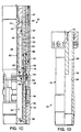
- FIGS. 1A-1D Representatively illustrated in FIGS. 1A-1D is an apparatus 10 which embodies principles of the present invention.
- directional terms such as “above”, “below”, “upper”, “lower”, etc., are used for convenience in referring to the accompanying drawings. Additionally, it is to be understood that the various embodiments of the present invention described herein may be utilized in various orientations, such as inclined, inverted, horizontal, vertical, etc., without departing from the principles of the present invention.
- the apparatus 10 includes a hydraulically actuatable well tool 12 and a hydraulic pressure generator 14.
- the well tool 12 is a conventional hydraulically settable packer of the type well known to those skilled in the art.
- the packer 12 is a model PHL packer available from Halliburton Energy Services, Inc. of Duncan, Oklahoma.
- the packer 12 could be any type of packer or other well tool which is hydraulically actuatable in a subterranean well.
- the packer 12 could be a valve which is opened and/or closed by application of fluid pressure thereto, a perforating gun firing head which fires upon application of fluid pressure thereto, etc.
- the apparatus 10 may utilize any of a wide variety of well tools without departing from the principles of the present invention.
- the hydraulic pressure generator 14 is axially reciprocably and sealingly received within the packer 12 as viewed in FIGS. 1A-1D. This configuration is desirable for convenient transfer of pressurized fluid directly from the hydraulic pressure generator 14 to the packer 12.
- the hydraulic pressure generator 14 may be otherwise positioned with respect to the packer 12 without departing from the principles of the present invention.
- the hydraulic pressure generator 14 could be positioned remote from the packer 12, but in fluid communication therewith, etc.
- the packer 12 is set in the well by application of a specific fluid pressure (the actuation pressure) to an inlet port 16 formed through a generally tubular mandrel 18 extending generally axially through the packer after the packer has been interconnected as a part of a tubing string installed in a well in a conventional manner.
- a specific fluid pressure the actuation pressure
- the hydraulic pressure generator 14 is conveyed into the well and a discharge port 20 formed through an outer housing assembly 22 of the hydraulic pressure generator is generally axially aligned with the inlet port 16 for fluid communication therewith.
- a pair of circumferential seals or packings 24 are carried externally on the housing assembly 22 axially straddling the discharge port 20 and serve to isolate the ports 16, 20 from fluids and pressures existing in the well.
- the packings 24 are sealingly received in an internal bore 26 of the mandrel 18. Note that a reduced diameter seal bore may be formed in the mandrel 18 (as indicated by the dashed lines 28 shown in FIG. 1C) if desired, so that the packings 24 may have a reduced diameter and be more protected against damage during conveyance into the packer 12.
- the hydraulic pressure generator 14 may be releasably secured in position by a conventional latching device (not shown) attached to an extension 30 attached to the housing assembly 22.
- the latching device may be engaged with a conventional internal latching profile (not shown) attached below the packer 12 in the tubing string.
- the hydraulic pressure generator 14 may be retained in position by engagement with the packer 12.
- the housing assembly 22 could engage an internal shoulder (indicated by dashed lines 32 in FIG. 1C) formed in the mandrel 18.
- the hydraulic pressure generator 14 may be retained relative to the packer 12 in any manner without departing from the principles of the present invention.
- the hydraulic pressure generator 14 is representatively conveyed in the well suspended from a line 34 attached to the housing assembly 22 via a conventional rope socket/fishing neck 36.
- the line 34 may be any of the conveyances well known to those skilled in the art, such as a slickline, electric line, wireline, etc. Of course, other forms of conveyance may be utilized as well, for example, coiled tubing, etc., without departing from the principles of the present invention.
- the line 34 is a slickline and the hydraulic pressure generator 14 is actuated by means of an electronic timing device 38 interconnected between a battery 40 and a valve 42.
- the hydraulic pressure generator 14 does not require an external electrical power source for its actuation.
- the electronic timing device 38 and battery 40 are conventional and may be of the type utilized in a model ETD battery powered controller available from Halliburton Energy Services, Inc.
- the electronic timing device 38 includes an accelerometer for detecting movement of the hydraulic pressure generator 14. When the hydraulic pressure generator 14 has remained motionless for a predetermined period of time, the electronic timing device 38 applies power from the battery 40 to the valve 42 to open the valve.
- the valve 42 may be a conventional one-shot valve available from BEI of Houston, Texas. However, it is to be clearly understood that other timing devices, power sources and valves may be utilized in the hydraulic pressure generator 14 without departing from the principles of the present invention.
- the valve 42 serves as a barrier device. It prevents fluid communication between the well external to the housing assembly 22 and a fluid chamber 44 formed in the housing assembly until opened. When opened, the valve 42 permits fluid communication between the chamber 44 and the well external to the housing assembly 22, thereby admitting fluid pressure in the well to the chamber 44.
- a filter 46 prevents contaminants from entering the housing assembly 22 when the valve 42 is opened.
- the valve 42 may be directly connected thereto, for example, using electric lines (indicated in FIG. 1B by dashed lines 48). In that case, the battery 40 and electronic timing device 38 may not be needed in the hydraulic pressure generator 14.
- the chamber 44 is separated from another chamber 50 formed within the housing assembly 22 by an upper portion 52 of a piston 54 sealingly and reciprocably received within the housing assembly.
- the chamber 50 is in fluid communication with the discharge port 20. It will be readily appreciated that if the piston 54 is displaced downwardly from its position representatively illustrated in FIG. 1C, the chamber 50 will decrease in volume and fluid in the chamber 50 will be pressurized, discharged through the discharge port 20 and forced into the inlet port 16.
- a conventional check valve 56 may be utilized to prevent contaminants from entering the chamber 50, while permitting discharge of fluid through the port 20.
- the piston 54 is made to displace downwardly when the valve 42 is opened as described above. Opening of the valve 42 permits well fluid pressure (which may be hydrostatic pressure, hydrostatic pressure plus some pressure applied at the earth's surface, etc.) to enter the chamber 44. The well fluid pressure, thus, applies a downwardly biasing force to the upper portion 52 of the piston 54.
- well fluid pressure which may be hydrostatic pressure, hydrostatic pressure plus some pressure applied at the earth's surface, etc.
- the chamber 44 is in fluid communication with another chamber 58 formed in the housing assembly 22 via a passage 60 formed through the piston 54.
- another chamber 62 is formed in the housing assembly 22, and is separated from the chamber 58 by a lower portion 64 of the piston 54.
- the chamber 62 may contain a fluid, such as air or nitrogen, at atmospheric pressure, or the fluid may be pressurized initially as needed to restrict, limit or diminish the pressure of the fluid discharged through the port 20 in a manner more fully described below.
- the upper portion 52 of the piston 54 presents an upper piston area of 3 sq. in. (19.4 cm 2 ) exposed to fluid pressure in the chamber 44, and a lower piston area of 2 sq. in. (12.9 cm 2 ) exposed to fluid pressure in the chamber 50; and assume that the lower portion 64 of the piston presents an upper piston area of 2 sq. in. (12.9 cm 2 ) exposed to fluid pressure in the chamber 58, and a lower piston area of 3 sq. in. (19.4 cm 2 ) exposed to fluid pressure in the chamber 62.
- Well fluid pressure in the chambers 44, 58 biases the piston 54 downward with 15,000 lbf (5 sq. in. x 3,000 psi, equivalent to 66.7 kN), and fluid pressure in the chamber 62 biases the piston upward with 300 lbf (3 sq. in. x 100 psi, equivalent to 1334 N).
- fluid pressure in the chamber 50 is 7,350 psi (15,000 lbf -300 lbf/ 2 sq. in., equivalent to 50.7 MPa). This amount is 4,350 psi (30 MPa) greater than the well fluid pressure of 3,000 psi (20.7 MPa).
- piston 54 has been described above as including the two portions 52, 64 separating the chambers 44, 50, 58, 62, greater increases in the amount by which the fluid pressure in the chamber 50 is elevated above well fluid pressure may be achieved by providing additional piston portions separating additional chamber pairs.
- the hydraulic pressure generator 14 could be constructed in a modular manner, with additional piston portions and chambers being added when it is desired to increase the pressure of fluid discharged from the port 20.
- the piston 54 and one or more of the chambers 44, 50, 58, 62 may be differently configured in other manners, without departing from the principles of the present invention.
- the packer 12 may be preferably set with an applied fluid pressure only 2,000 psi (13.8 MPa) greater than well fluid pressure.
- fluid pressure in the chamber 62 may be initially elevated above atmospheric pressure by, for example, charging the chamber 62 with nitrogen at an elevated pressure via a charging port 66.
- the chamber 62 should be charged to 1,667 psi (15,000 lbf - (5,000 psi x 2 sq. in.)) / 3 sq. in., equivalent to 11.5 MPa).
- a pressure relief device 68 such as a conventional rupture disc or relief valve, may be installed in the housing assembly 22 to vent fluid pressure in the chamber 50 to the well when the fluid pressure exceeds well fluid pressure by a predetermined amount.
- the chamber 50, the stroke of the piston 54, etc. may be adjusted so that only a predetermined desired volume of fluid is discharged from the port 20.
- the piston 54 is retained in its upper position as shown in FIG. 1C by that elevated fluid pressure in the chamber 62 until the valve 42 is opened.
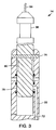
- FIG. 2 depicts an alternate means of actuating the hydraulic pressure generator 14, which requires no electrical power source at all.
- the barrier device utilized to selectively permit fluid communication between the well external to the housing assembly 22 and the chambers 44, 58 is a frangible plug or kobe 70.
- the plug 70 When the plug 70 is broken, well fluid pressure is placed in communication with the chambers 44, 58 via a passage 72 extending downwardly to the chamber 44 from the plug.
- operation of the hydraulic pressure generator 14 is substantially the same as described above for the embodiment shown in FIGS. 1A-1D.
- an inclined lower face 74 is displaced axially downward into contact with the plug.
- a shear pin 76 prevents accidental impact of the face 74 with the plug 70 as the hydraulic pressure generator 14 is being conveyed in the well.
- conventional weights, jars, etc. may be interconnected between the rope socket 36 and the face 74 in a conventional manner.
- a generally cylindrical shuttle 78 is utilized as a barrier device to selectively permit communication between the well fluid pressure and the chambers 44, 58.
- the shuttle 78 is sealingly and reciprocably received in the housing assembly 22 and initially prevents communication between well fluid pressure and the chambers 44, 58 in its upwardly disposed position as depicted in FIG. 3. However, when jarred downwardly as described above in relation to the embodiment shown in FIG. 2, the shear pin 76 shears and the shuttle 78 displaces downwardly. A reduced diameter portion 80 formed on the shuttle 78 then permits communication between well fluid pressure and the passage 72, which extends downwardly to the chamber 44.
Landscapes
- Life Sciences & Earth Sciences (AREA)
- Engineering & Computer Science (AREA)
- Geology (AREA)
- Mining & Mineral Resources (AREA)
- Physics & Mathematics (AREA)
- Environmental & Geological Engineering (AREA)
- Fluid Mechanics (AREA)
- General Life Sciences & Earth Sciences (AREA)
- Geochemistry & Mineralogy (AREA)
- Supply Devices, Intensifiers, Converters, And Telemotors (AREA)
- Earth Drilling (AREA)
Applications Claiming Priority (2)
| Application Number | Priority Date | Filing Date | Title |
|---|---|---|---|
| US18479398A | 1998-11-02 | 1998-11-02 | |
| US184793 | 1998-11-02 |
Publications (2)
| Publication Number | Publication Date |
|---|---|
| EP1002933A2 true EP1002933A2 (de) | 2000-05-24 |
| EP1002933A3 EP1002933A3 (de) | 2002-01-23 |
Family
ID=22678356
Family Applications (1)
| Application Number | Title | Priority Date | Filing Date |
|---|---|---|---|
| EP99307942A Withdrawn EP1002933A3 (de) | 1998-11-02 | 1999-10-08 | Hydraulicher Bohrlochdruckgenerator |
Country Status (1)
| Country | Link |
|---|---|
| EP (1) | EP1002933A3 (de) |
Cited By (3)
| Publication number | Priority date | Publication date | Assignee | Title |
|---|---|---|---|---|
| GB2435655A (en) * | 2006-03-03 | 2007-09-05 | Schlumberger Holdings | Pressure protection for a control chamber of a well tool |
| WO2009067021A3 (en) * | 2007-11-23 | 2009-09-17 | Aker Well Service As | Method and device for determination of fluid inflow to a well |
| CN108661594A (zh) * | 2018-05-18 | 2018-10-16 | 中国石油天然气股份有限公司 | 火驱封隔器 |
Family Cites Families (5)
| Publication number | Priority date | Publication date | Assignee | Title |
|---|---|---|---|---|
| US3295615A (en) * | 1965-10-22 | 1967-01-03 | Schlumberger Well Surv Corp | Formation-testing apparatus |
| US4254838A (en) * | 1979-07-24 | 1981-03-10 | Eduardo Barnetche | Automatic depth compensating device |
| US4745802A (en) * | 1986-09-18 | 1988-05-24 | Halliburton Company | Formation testing tool and method of obtaining post-test drawdown and pressure readings |
| US5624001A (en) * | 1995-06-07 | 1997-04-29 | Dailey Petroleum Services Corp | Mechanical-hydraulic double-acting drilling jar |
| US5947205A (en) * | 1996-06-20 | 1999-09-07 | Halliburton Energy Services, Inc. | Linear indexing apparatus with selective porting |
-
1999
- 1999-10-08 EP EP99307942A patent/EP1002933A3/de not_active Withdrawn
Cited By (6)
| Publication number | Priority date | Publication date | Assignee | Title |
|---|---|---|---|---|
| GB2435655A (en) * | 2006-03-03 | 2007-09-05 | Schlumberger Holdings | Pressure protection for a control chamber of a well tool |
| GB2435655B (en) * | 2006-03-03 | 2009-02-18 | Schlumberger Holdings | Pressure protection for a control chamber of a well tool |
| US7938189B2 (en) | 2006-03-03 | 2011-05-10 | Schlumberger Technology Corporation | Pressure protection for a control chamber of a well tool |
| NO339374B1 (no) * | 2006-03-03 | 2016-12-05 | Schlumberger Technology Bv | Fremgangsmåte og anordning for trykkontroll av et kontrollkammer i et brønnverktøy |
| WO2009067021A3 (en) * | 2007-11-23 | 2009-09-17 | Aker Well Service As | Method and device for determination of fluid inflow to a well |
| CN108661594A (zh) * | 2018-05-18 | 2018-10-16 | 中国石油天然气股份有限公司 | 火驱封隔器 |
Also Published As
| Publication number | Publication date |
|---|---|
| EP1002933A3 (de) | 2002-01-23 |
Similar Documents
| Publication | Publication Date | Title |
|---|---|---|
| US4544034A (en) | Actuation of a gun firing head | |
| US6431276B1 (en) | Remote actuated plug apparatus | |
| US7896091B2 (en) | Convertible seal | |
| EP0477452B1 (de) | Krafterzeuger zur Verwendung im Bohrloch | |
| EP0615053B1 (de) | Bohrlochperforationssystem | |
| US2978029A (en) | Plug for well boreholes | |
| US5845712A (en) | Apparatus and associated methods for gravel packing a subterranean well | |
| US6199632B1 (en) | Selectively locking locator | |
| US5971070A (en) | Apparatus for completing a subterranean well and associated methods | |
| CA2445870C (en) | Automatic tubing filler | |
| US6070672A (en) | Apparatus and method for downhole tool actuation | |
| GB2327445A (en) | Fluid pressure operable downhole tool | |
| EP1101012A1 (de) | Verfahren zum einbringen mehrerer kugeln in rohre, welche beim bohren, komplettieren und überarbeiten von brunnen verwendet werden | |
| AU721013B2 (en) | Pressure activated switch valve | |
| EP0354979A2 (de) | Pendelventil im Bohrloch | |
| US4690227A (en) | Gun firing head | |
| US5253712A (en) | Rotationally operated back pressure valve | |
| US7055596B2 (en) | Packer releasing methods | |
| EP1747345B1 (de) | Hydraulisch eingestellter konzentrischer packer mit nabelumleitung durch den kolben | |
| GB2138925A (en) | Firing of well perforation guns | |
| EP1002933A2 (de) | Hydraulicher Bohrlochdruckgenerator | |
| US11208869B2 (en) | Static packer plug | |
| US5370187A (en) | Over-pressured well fracturing method | |
| US11346192B2 (en) | Pressure activated firing heads, perforating gun assemblies, and method to set off a downhole explosion | |
| EP4256171B1 (de) | Doppelkugelsitzsystem |
Legal Events
| Date | Code | Title | Description |
|---|---|---|---|
| PUAI | Public reference made under article 153(3) epc to a published international application that has entered the european phase |
Free format text: ORIGINAL CODE: 0009012 |
|
| AK | Designated contracting states |
Kind code of ref document: A2 Designated state(s): AT BE CH CY DE DK ES FI FR GB GR IE IT LI LU MC NL PT SE |
|
| AX | Request for extension of the european patent |
Free format text: AL;LT;LV;MK;RO;SI |
|
| PUAL | Search report despatched |
Free format text: ORIGINAL CODE: 0009013 |
|
| AK | Designated contracting states |
Kind code of ref document: A3 Designated state(s): AT BE CH CY DE DK ES FI FR GB GR IE IT LI LU MC NL PT SE |
|
| AX | Request for extension of the european patent |
Free format text: AL;LT;LV;MK;RO;SI |
|
| AKX | Designation fees paid | ||
| STAA | Information on the status of an ep patent application or granted ep patent |
Free format text: STATUS: THE APPLICATION IS DEEMED TO BE WITHDRAWN |
|
| REG | Reference to a national code |
Ref country code: DE Ref legal event code: 8566 |
|
| 18D | Application deemed to be withdrawn |
Effective date: 20020503 |