EP1002910A2 - Hinged connecting section - Google Patents
Hinged connecting section Download PDFInfo
- Publication number
- EP1002910A2 EP1002910A2 EP99309261A EP99309261A EP1002910A2 EP 1002910 A2 EP1002910 A2 EP 1002910A2 EP 99309261 A EP99309261 A EP 99309261A EP 99309261 A EP99309261 A EP 99309261A EP 1002910 A2 EP1002910 A2 EP 1002910A2
- Authority
- EP
- European Patent Office
- Prior art keywords
- section
- hinge
- receiving
- pivot
- integral
- Prior art date
- Legal status (The legal status is an assumption and is not a legal conclusion. Google has not performed a legal analysis and makes no representation as to the accuracy of the status listed.)
- Withdrawn
Links
Images

Classifications
-
- E—FIXED CONSTRUCTIONS
- E04—BUILDING
- E04H—BUILDINGS OR LIKE STRUCTURES FOR PARTICULAR PURPOSES; SWIMMING OR SPLASH BATHS OR POOLS; MASTS; FENCING; TENTS OR CANOPIES, IN GENERAL
- E04H17/00—Fencing, e.g. fences, enclosures, corrals
- E04H17/14—Fences constructed of rigid elements, e.g. with additional wire fillings or with posts
- E04H17/1413—Post-and-rail fences, e.g. without vertical cross-members
- E04H17/1447—Details of connections between rails and posts
- E04H17/1448—Adjustable, angled or hinged connections
-
- A—HUMAN NECESSITIES
- A01—AGRICULTURE; FORESTRY; ANIMAL HUSBANDRY; HUNTING; TRAPPING; FISHING
- A01G—HORTICULTURE; CULTIVATION OF VEGETABLES, FLOWERS, RICE, FRUIT, VINES, HOPS OR SEAWEED; FORESTRY; WATERING
- A01G9/00—Cultivation in receptacles, forcing-frames or greenhouses; Edging for beds, lawn or the like
- A01G9/28—Raised beds; Planting beds; Edging elements for beds, lawn or the like, e.g. tiles
-
- E—FIXED CONSTRUCTIONS
- E04—BUILDING
- E04B—GENERAL BUILDING CONSTRUCTIONS; WALLS, e.g. PARTITIONS; ROOFS; FLOORS; CEILINGS; INSULATION OR OTHER PROTECTION OF BUILDINGS
- E04B1/00—Constructions in general; Structures which are not restricted either to walls, e.g. partitions, or floors or ceilings or roofs
- E04B1/18—Structures comprising elongated load-supporting parts, e.g. columns, girders, skeletons
- E04B1/26—Structures comprising elongated load-supporting parts, e.g. columns, girders, skeletons the supporting parts consisting of wood
- E04B1/2604—Connections specially adapted therefor
- E04B2001/2616—Hinged connections of wooden members
Definitions
- the invention relates generally to apparatus for constructing walls and supports, and in particular, to an hinged outdoor building structure having position locking capabilities.
- fence-type support structures are needed to define separations between two areas.
- the structure may act simply as a divider, such as a fence, or it may act to hold back an earthen area, for example a free standing garden, a terraced grade, etc.
- a divider such as a fence
- earthen area for example a free standing garden, a terraced grade, etc.
- fence-type structures may be tall, or the structures may be used to hold back or enclose large masses of earth and other fill, the final structure should be strong enough to withstand normal use and harsh environments.
- Another object of the invention is to provide a flexible, inexpensive, easily used, building aid in the construction of fence-like structures. Another object of the invention is to enable a single connector or link section to be flexibly used by the casual builder as well as the more professional builder to provide an attractive and stable structure.
- the invention relates to an integral hinge section featuring a receiving section for securely receiving an elongated building member and a pivot section integral with the receiving section enable to lockably mate in any of a plurality of angular positions with an inverted pivot section of a second hinge section.
- the invention further relates, in a particular embodiment, to an integral hinge section featuring a receiving section defining an open cavity for receiving an elongated building member, sides of the section having pass-through fastener access holes, and an integral solid rounded pivot section, the base of which extends from a closed end of the receiving section and which has a hinge pass-through opening.
- the solid pivot section is preferably substantially coplanar with the receiving section along one surface normal to the hinge pass-through opening and is no more than half the height of the receiving section in the direction of the hinge pass-through opening.
- the solid pivot section has at least one locking pin and at least one pin receiving hole in a surface at an opposite side of the pivot section to the one normal surface.
- the pivot section features a height which is one half the height of the receiving section. Further, the pivot section has one locking pin and a plurality of pin receiving holes, and the receiving section is a substantially squared off U-shaped section in which the fastener holes are in the legs of the section.
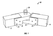
- a system 10 for connecting to elongated building members 12 and 14 in a selectively fixed hinged arrangement has, in this illustrated embodiment, two identical hinge supporting sections 16 and 20.
- the elongated members 12 and 14 are connected in a fixed arrangement using screw elements 24 to the respective hinge sections 16 and 20.
- the hinge sections interconnect in a stable environment using a hinge pin 26.
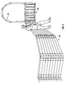
- each hinge section has a squared-off, preferably U-shaped receiving section 30 for receiving an elongated building member and is configured for attaching the elongated member to the receiving section 30 of the hinge section.
- a preferred structural arrangement includes pass through screw openings 23 through which screws 24 engage and hold the building elements to the hinge section.
- Integral with and attached to the receiving section 30 is a pivot section 32.
- the pivot section is preferably a solid element, in the preferred embodiment of the invention, having a rounded, U-shaped end 34 and a pass through opening 36 into which a hinge pin can be inserted.
- the U-shaped cross section of the pivot section 34 extends from the receiving section 30.
- the height of the hinge section is half the height of the receiving section so that when two end sections are hingedly interconnected in a locked position, the total height of the assembly is substantially constant.
- Each hinge section 16, 20 has on a face 40 of the pivot section, a plurality of spaced holes 42 and a pin member 44.
- the respective pins 44 are positioned to insert into one of the plurality of hole members 42 on the opposite juxtaposed section.
- the relative angular position of the two sections is fixed and immovable, although it can be easily changed to suit the user by lifting the sections apart and repositioning the pins.
- a plurality of different fixed angular positions can be obtained, depending upon the need of the installation.
- a fence 60 ( Figure 3) or earth enclosure can be constructed.
- the hinged sections can also be employed for providing many hinged arrangements, for example, for swinging gates 66 or archways 68.
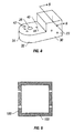
- the U-shaped receiving section can be other than squared-off in shape, and may be closed at its top and bottom (Figs. 4 and 5) to provide a greater structural integrity if desired.
- the cavity formed by walls 100 receives the elongated building member.
- the section need not be a solid member but may be hollowed or open in order to reduce its weight, provided the necessary structural integrity is maintained.
- a U-shaped section is preferred, other cross-sectional shapes, which functionally achieve the result within the scope of the description herein, can be employed.
Abstract
Description
- The invention relates generally to apparatus for constructing walls and supports, and in particular, to an hinged outdoor building structure having position locking capabilities.
- It often occurs, in connection with outdoor landscaping, that fence-type support structures are needed to define separations between two areas. The structure may act simply as a divider, such as a fence, or it may act to hold back an earthen area, for example a free standing garden, a terraced grade, etc. For ease of use, and economy, it is desirable that such structures have great flexibility, enabling the user, often an individual who is not a professional in this field, to be able to plan the structure without requiring a substantial outlay for specialized tools, and/or custom cut parts. It is also desirable even after the planning stage, and in the building stage, to be able to vary the original plan without loss of material.
- Furthermore, since fence-type structures may be tall, or the structures may be used to hold back or enclose large masses of earth and other fill, the final structure should be strong enough to withstand normal use and harsh environments.
- Accordingly, it is an object of the invention to provide a flexible, inexpensive, easily used, building aid in the construction of fence-like structures. Another object of the invention is to enable a single connector or link section to be flexibly used by the casual builder as well as the more professional builder to provide an attractive and stable structure.
- The invention relates to an integral hinge section featuring a receiving section for securely receiving an elongated building member and a pivot section integral with the receiving section enable to lockably mate in any of a plurality of angular positions with an inverted pivot section of a second hinge section.
- The invention further relates, in a particular embodiment, to an integral hinge section featuring a receiving section defining an open cavity for receiving an elongated building member, sides of the section having pass-through fastener access holes, and an integral solid rounded pivot section, the base of which extends from a closed end of the receiving section and which has a hinge pass-through opening. The solid pivot section is preferably substantially coplanar with the receiving section along one surface normal to the hinge pass-through opening and is no more than half the height of the receiving section in the direction of the hinge pass-through opening. The solid pivot section has at least one locking pin and at least one pin receiving hole in a surface at an opposite side of the pivot section to the one normal surface.
- In particular embodiments, the pivot section features a height which is one half the height of the receiving section. Further, the pivot section has one locking pin and a plurality of pin receiving holes, and the receiving section is a substantially squared off U-shaped section in which the fastener holes are in the legs of the section.
- Other objects, features and advantages of the invention will be apparent from the following description, taken together with the drawings, in which:
- Figure 1 is a perspective view of a pair of hinge sections in accordance with the invention;
- Figure 2 is an assembly view, without building members, of the hinge section of Figure 1;
- Figure 3 is one illustrative illustration of the use of the hinge sections in the construction of a fence having a hinged gate opening;
- Figure 4 is a perspective view of the hinge section according to an alternate embodiment of the invention; and
- Figure 5 is a cross-sectional view of the hinge section of Figure 4.
-
- Referring to Figure 1, a
system 10 for connecting toelongated building members hinge supporting sections elongated members screw elements 24 to therespective hinge sections hinge pin 26. - Referring more particularly to Figure 2, each hinge section has a squared-off, preferably U-shaped receiving
section 30 for receiving an elongated building member and is configured for attaching the elongated member to the receivingsection 30 of the hinge section. As illustrated herein, a preferred structural arrangement includes pass throughscrew openings 23 through whichscrews 24 engage and hold the building elements to the hinge section. Integral with and attached to the receivingsection 30 is apivot section 32. The pivot section is preferably a solid element, in the preferred embodiment of the invention, having a rounded,U-shaped end 34 and a pass through opening 36 into which a hinge pin can be inserted. The U-shaped cross section of thepivot section 34 extends from thereceiving section 30. In the preferred embodiment of the invention, the height of the hinge section is half the height of the receiving section so that when two end sections are hingedly interconnected in a locked position, the total height of the assembly is substantially constant. - Each
hinge section face 40 of the pivot section, a plurality of spacedholes 42 and apin member 44. When two hinge sections are placed in an operative relationship to each other, as illustrated in Fig. 5, therespective pins 44 are positioned to insert into one of the plurality ofhole members 42 on the opposite juxtaposed section. When so inserted, the relative angular position of the two sections is fixed and immovable, although it can be easily changed to suit the user by lifting the sections apart and repositioning the pins. In this manner, a plurality of different fixed angular positions can be obtained, depending upon the need of the installation. Thus, for example, a fence 60 (Figure 3) or earth enclosure can be constructed. Indeed, the hinged sections can also be employed for providing many hinged arrangements, for example, for swinginggates 66 or archways 68. - Different hinge arrangements will be desirable depending upon the nature of the structure being constructed. Thus, for a fence structure as illustrated in Figure 3, it will likely be desirable to use a long single rod as the hinge element, the rod passing through a plurality of hinge assemblies and forced into the earth, for example by using a hammer. The top of the structure can then be advantageously capped to provide a neat and attractive appearance. On the other hand, in connection with a swinging gate structure, while the bottom hinge connection can be stabilized by driving a pivot rod into the earth, the upper gate hinge pair are stabilized using a nut and bolt hinge arrangement. In either instance, suitable ornamental capping can be applied to present a neat and attractive appearance.
- While the invention has been illustrated with a particular shape and securing structure, it should be clear to one of skill in the field that other shapes will be equally practical. Thus, for example, the height of the various elements need not be equal to provide a constant height surface when in a final arrangement. Further, the U-shaped receiving section can be other than squared-off in shape, and may be closed at its top and bottom (Figs. 4 and 5) to provide a greater structural integrity if desired. (Here, the cavity formed by
walls 100 receives the elongated building member.) Similarly, the section need not be a solid member but may be hollowed or open in order to reduce its weight, provided the necessary structural integrity is maintained. Similarly, while a U-shaped section is preferred, other cross-sectional shapes, which functionally achieve the result within the scope of the description herein, can be employed. - Additions, subtractions, and other modifications of the described invention will be apparent to those practiced in this field and are within the scope of the following claims.
Claims (11)
- An integral hinge section comprisinga receiving section for securely receiving an elongated building member, anda pivot section integral with the receiving section and able to lockably mate, in any of a plurality of angular positions, with an inverted pivot section of a second hinge section.
- An integral hinge section comprisinga receiving section defining an open cavity for receiving an elongated building member, at least one side of the section having pass-through fastener access holes, andan integral solid rounded pivot section extending from a closed end of said receiving section and having a hinge pass-through opening,said solid pivot section being substantially co-planar with said receiving section along one surface normal to said hinge pass-through opening and having no more than half the height of said receiving section in the direction of said hinge pass-through opening, andsaid solid pivot section having at least one locking pin and at least one pin receiving hole in a surface at an opposite side of said pivot section to said one normal surface.
- The hinge section of claim 2 wherein said pivot section has a height which is one-half the height of the receiving section.
- The hinge section of claim 2 wherein said pivot section has one locking pin and a plurality of pin receiving holes.
- The hinge section of claim 2 further wherein said receiving section is a substantially squared off U-shaped section and said fastener holes are in the legs of the squared-off section.
- The hinge section of claim 5 further wherein said pivot section has a substantially circular cross-sectional shape at a base of a U-shape.
- The hinge section of claim 2 wherein said hinge pass-through opening is normal to said fastener access holes.
- The hinge section of claim 2 wherein the receiving section is closed at its top and bottom surfaces.
- An integral hinge section comprisinga U-shaped receiving section defining an open cavity for receiving an elongated building member, at least one side of the U-shaped section having pass-through fastener access holes, andan integral, solid, rounded, U-shaped pivot section extending from a closed end of the U-shaped receiving section and having a hinge pass-through opening normal to its U-shaped cross section, the pivot section having a height which is one-half the height of the receiving section in a direction normal to said U-shaped cross section, the pivot section having a locking pin and a plurality of pin receiving holes in a surface opposite to a side of the pivot section which is substantially co-planar with the receiving section along one surface thereof, andsaid receiving section being substantially a squared-off U-shaped section and the fastener holes being in the legs of the squared-off section, andthe hinge pass-through opening being normal to the plane of the fastener access holes.
- A support assembly having a plurality of hinged interlocking rotatable and lockable sections, each section having an elongated building member, the building member having, at at least one end, an integral hinge section comprisinga receiving section for securely receiving the elongated building member, anda pivot section integral with the receiving section and able to lockably mate, in any of a plurality of angular positions, with an inverted pivot section of a second hinge section connected to a different elongated building member.
- The assembly of claim 10 further comprising at least one hinge pin extending through a plurality of the integral hinge sections for providing a common axis of rotation for each of the lockable integral hinge sections.
Applications Claiming Priority (2)
| Application Number | Priority Date | Filing Date | Title |
|---|---|---|---|
| US197098 | 1988-05-20 | ||
| US19709898A | 1998-11-20 | 1998-11-20 |
Publications (2)
| Publication Number | Publication Date |
|---|---|
| EP1002910A2 true EP1002910A2 (en) | 2000-05-24 |
| EP1002910A3 EP1002910A3 (en) | 2001-10-24 |
Family
ID=22728048
Family Applications (1)
| Application Number | Title | Priority Date | Filing Date |
|---|---|---|---|
| EP99309261A Withdrawn EP1002910A3 (en) | 1998-11-20 | 1999-11-22 | Hinged connecting section |
Country Status (1)
| Country | Link |
|---|---|
| EP (1) | EP1002910A3 (en) |
Cited By (9)
| Publication number | Priority date | Publication date | Assignee | Title |
|---|---|---|---|---|
| WO2002002891A1 (en) * | 2000-07-05 | 2002-01-10 | Vogue Pool Products | Above ground swimming pool support structure |
| GB2374094A (en) * | 2001-03-08 | 2002-10-09 | S & B Building Equipment Ltd | Hoarding, e.g. to surround construction site |
| GB2344117B (en) * | 1998-11-27 | 2003-07-09 | Darfen Ltd | Fence connector |
| FR2875525A1 (en) * | 2004-09-20 | 2006-03-24 | Raymond Jean Louis Larzul | Fencing or protective barrier e.g. swimming pool barrier, panel fixing device, has tightening cam with two jaws interlocked by tightening, using traversing bolts, around post, and pivoting slugs to receive pin of panel to orient it |
| WO2008146013A2 (en) * | 2007-05-31 | 2008-12-04 | Richard Burbidge Limited | Handrails |
| KR100990516B1 (en) | 2010-06-30 | 2010-10-29 | 주식회사 이지건축 | Flower garden fence for building |
| JP2020007838A (en) * | 2018-07-11 | 2020-01-16 | 有限会社大昌 | Fence for slope and installation method of fence for slope |
| US20230287704A1 (en) * | 2023-05-17 | 2023-09-14 | Long Xiang Shen | Height adjustable and detachable fence system |
| US11891831B1 (en) | 2018-07-17 | 2024-02-06 | Ameristar Perimeter Security Usa Inc. | Infill-covered barrier |
Citations (9)
| Publication number | Priority date | Publication date | Assignee | Title |
|---|---|---|---|---|
| US2037736A (en) * | 1934-12-14 | 1936-04-21 | Crane Packing Co | Jointed structure |
| US3495857A (en) * | 1968-04-12 | 1970-02-17 | Eugene E Hawke | Universally adjustable couplings |
| US3537687A (en) * | 1967-09-25 | 1970-11-03 | Philip Adelman | Garden fence and wall |
| DE2453917A1 (en) * | 1974-11-14 | 1976-05-26 | Anger Kunststoff | Lattice work bar connection system - has externally toothed tube on one bar engaging in complementary eye (NL180376) |
| US4174096A (en) * | 1977-06-06 | 1979-11-13 | Richard G. Miller | Fence |
| US4190304A (en) * | 1976-09-30 | 1980-02-26 | Schneider Robert J | Apparatus for use in the construction and decoration of upholstered furniture and the like |
| FR2470892A1 (en) * | 1979-12-06 | 1981-06-12 | Guillaumond Gabriel | Coupling plates for assembly of beams - has tongued channel-shaped elements fitted to ends of beams and joined by U=shaped element |
| US5168678A (en) * | 1991-11-07 | 1992-12-08 | Thompson Industries, Inc. | Modular landscaping system and structures |
| US5901526A (en) * | 1996-04-30 | 1999-05-11 | Hanover Catalog Holdings, Inc. | Landscape timber connecting system |
-
1999
- 1999-11-22 EP EP99309261A patent/EP1002910A3/en not_active Withdrawn
Patent Citations (9)
| Publication number | Priority date | Publication date | Assignee | Title |
|---|---|---|---|---|
| US2037736A (en) * | 1934-12-14 | 1936-04-21 | Crane Packing Co | Jointed structure |
| US3537687A (en) * | 1967-09-25 | 1970-11-03 | Philip Adelman | Garden fence and wall |
| US3495857A (en) * | 1968-04-12 | 1970-02-17 | Eugene E Hawke | Universally adjustable couplings |
| DE2453917A1 (en) * | 1974-11-14 | 1976-05-26 | Anger Kunststoff | Lattice work bar connection system - has externally toothed tube on one bar engaging in complementary eye (NL180376) |
| US4190304A (en) * | 1976-09-30 | 1980-02-26 | Schneider Robert J | Apparatus for use in the construction and decoration of upholstered furniture and the like |
| US4174096A (en) * | 1977-06-06 | 1979-11-13 | Richard G. Miller | Fence |
| FR2470892A1 (en) * | 1979-12-06 | 1981-06-12 | Guillaumond Gabriel | Coupling plates for assembly of beams - has tongued channel-shaped elements fitted to ends of beams and joined by U=shaped element |
| US5168678A (en) * | 1991-11-07 | 1992-12-08 | Thompson Industries, Inc. | Modular landscaping system and structures |
| US5901526A (en) * | 1996-04-30 | 1999-05-11 | Hanover Catalog Holdings, Inc. | Landscape timber connecting system |
Cited By (10)
| Publication number | Priority date | Publication date | Assignee | Title |
|---|---|---|---|---|
| GB2344117B (en) * | 1998-11-27 | 2003-07-09 | Darfen Ltd | Fence connector |
| WO2002002891A1 (en) * | 2000-07-05 | 2002-01-10 | Vogue Pool Products | Above ground swimming pool support structure |
| GB2374094A (en) * | 2001-03-08 | 2002-10-09 | S & B Building Equipment Ltd | Hoarding, e.g. to surround construction site |
| FR2875525A1 (en) * | 2004-09-20 | 2006-03-24 | Raymond Jean Louis Larzul | Fencing or protective barrier e.g. swimming pool barrier, panel fixing device, has tightening cam with two jaws interlocked by tightening, using traversing bolts, around post, and pivoting slugs to receive pin of panel to orient it |
| WO2008146013A2 (en) * | 2007-05-31 | 2008-12-04 | Richard Burbidge Limited | Handrails |
| WO2008146013A3 (en) * | 2007-05-31 | 2009-02-19 | Burbidge Richard Ltd | Handrails |
| KR100990516B1 (en) | 2010-06-30 | 2010-10-29 | 주식회사 이지건축 | Flower garden fence for building |
| JP2020007838A (en) * | 2018-07-11 | 2020-01-16 | 有限会社大昌 | Fence for slope and installation method of fence for slope |
| US11891831B1 (en) | 2018-07-17 | 2024-02-06 | Ameristar Perimeter Security Usa Inc. | Infill-covered barrier |
| US20230287704A1 (en) * | 2023-05-17 | 2023-09-14 | Long Xiang Shen | Height adjustable and detachable fence system |
Also Published As
| Publication number | Publication date |
|---|---|
| EP1002910A3 (en) | 2001-10-24 |
Similar Documents
| Publication | Publication Date | Title |
|---|---|---|
| US7249755B2 (en) | Gate bracket systems and methods | |
| US5362030A (en) | Fence post module | |
| US5238321A (en) | Modular construction system | |
| US4922678A (en) | Structural assembly for producing interconnecting structures | |
| US5470139A (en) | Combined display case | |
| KR101992245B1 (en) | Corner piece for mechanically interlocking frame members | |
| US4748913A (en) | Powered desk | |
| US5167049A (en) | Square frame hinge | |
| US5009541A (en) | Plastic barricade with limiting bolt | |
| EP1002910A2 (en) | Hinged connecting section | |
| US4421434A (en) | Clamp members | |
| CA2505082A1 (en) | Interlocking privacy fence | |
| US3442057A (en) | Offcenter a-frame building structure | |
| CA2013693C (en) | Picket fence joint | |
| US4240764A (en) | Display structure | |
| US20040129848A1 (en) | Adjustable gate bracket system and method | |
| EP0383427B1 (en) | Display panel assembly | |
| US5695166A (en) | Post support | |
| EP1092365B1 (en) | Piece of furniture | |
| US8556235B2 (en) | Gate bracket systems and methods | |
| JP3347089B2 (en) | desk | |
| EP1219839A1 (en) | System for fixing fences or panels to support structure posts | |
| CA2040926C (en) | Structural panel connector for space dividing system | |
| US20050000169A1 (en) | Shanty and a system and a method for assembling the same | |
| GB2337557A (en) | Tie and a partitioning system |
Legal Events
| Date | Code | Title | Description |
|---|---|---|---|
| PUAI | Public reference made under article 153(3) epc to a published international application that has entered the european phase |
Free format text: ORIGINAL CODE: 0009012 |
|
| AK | Designated contracting states |
Kind code of ref document: A2 Designated state(s): AT BE CH CY DE DK ES FI FR GB GR IE IT LI LU MC NL PT SE |
|
| AX | Request for extension of the european patent |
Free format text: AL;LT;LV;MK;RO;SI |
|
| PUAL | Search report despatched |
Free format text: ORIGINAL CODE: 0009013 |
|
| AK | Designated contracting states |
Kind code of ref document: A3 Designated state(s): AT BE CH CY DE DK ES FI FR GB GR IE IT LI LU MC NL PT SE |
|
| AX | Request for extension of the european patent |
Free format text: AL;LT;LV;MK;RO;SI |
|
| AKX | Designation fees paid | ||
| REG | Reference to a national code |
Ref country code: DE Ref legal event code: 8566 |
|
| STAA | Information on the status of an ep patent application or granted ep patent |
Free format text: STATUS: THE APPLICATION IS DEEMED TO BE WITHDRAWN |
|
| 18D | Application deemed to be withdrawn |
Effective date: 20020601 |