EP1002598B1 - Device for cold-forming deep holes - Google Patents
Device for cold-forming deep holes Download PDFInfo
- Publication number
- EP1002598B1 EP1002598B1 EP99300496A EP99300496A EP1002598B1 EP 1002598 B1 EP1002598 B1 EP 1002598B1 EP 99300496 A EP99300496 A EP 99300496A EP 99300496 A EP99300496 A EP 99300496A EP 1002598 B1 EP1002598 B1 EP 1002598B1
- Authority
- EP
- European Patent Office
- Prior art keywords
- clamping pieces
- deep hole
- face
- punch
- clamp holder
- Prior art date
- Legal status (The legal status is an assumption and is not a legal conclusion. Google has not performed a legal analysis and makes no representation as to the accuracy of the status listed.)
- Expired - Lifetime
Links
- 239000012530 fluid Substances 0.000 claims description 24
- 238000000034 method Methods 0.000 description 11
- 238000010273 cold forging Methods 0.000 description 3
- 230000000452 restraining effect Effects 0.000 description 3
- 238000000605 extraction Methods 0.000 description 2
- 230000015572 biosynthetic process Effects 0.000 description 1
- 238000005242 forging Methods 0.000 description 1
Images


Classifications
-
- B—PERFORMING OPERATIONS; TRANSPORTING
- B21—MECHANICAL METAL-WORKING WITHOUT ESSENTIALLY REMOVING MATERIAL; PUNCHING METAL
- B21J—FORGING; HAMMERING; PRESSING METAL; RIVETING; FORGE FURNACES
- B21J5/00—Methods for forging, hammering, or pressing; Special equipment or accessories therefor
- B21J5/06—Methods for forging, hammering, or pressing; Special equipment or accessories therefor for performing particular operations
- B21J5/12—Forming profiles on internal or external surfaces
-
- B—PERFORMING OPERATIONS; TRANSPORTING
- B21—MECHANICAL METAL-WORKING WITHOUT ESSENTIALLY REMOVING MATERIAL; PUNCHING METAL
- B21J—FORGING; HAMMERING; PRESSING METAL; RIVETING; FORGE FURNACES
- B21J13/00—Details of machines for forging, pressing, or hammering
- B21J13/02—Dies or mountings therefor
- B21J13/025—Dies with parts moving along auxiliary lateral directions
Definitions
- the present invention relates to a cold deep hole forming device, especially a cold deep hole forming device used for forming, by the method of cold forging, deep hole for involute spline, etc., in member to be formed partially different in thickness.
- B which indicates changes of BBD (Between Ball Diameter) from end face to inner part of the member W to be formed of an involute spline formed by said conventional cold deep hole forming device, shows that the involute spline formed is of poor accuracy, deviating from the upper and lower limit values of BBD, in the range of effective length of the spline), especially in the case where the object member W to be formed is partially different in thickness as shown in Fig. 1 and Fig. 2, thus making it impossible to obtain formed pieces of high accuracy.
- BBD Between Ball Diameter
- the objective of the present invention is to provide a cold deep hole forming device capable of forming, in a simple way, by cold forging, a deep hole for involute spline, etc. with high accuracy, even if the member to be formed has partially different thickness, in view of the problems of the said conventional cold deep hole forming device.
- the cold deep hole forming device is a cold deep hole forming device comprised of a supporting base to support the member to be formed and a punch for forming a deep hole in the member to be formed, characterized in that a clamp holder is provided on the outer circumference of said punch, that a clamp composed by circumferentially disposing a plurality of split clamping pieces is disposed in said clamp holder, and that, when forming a deep hole in the member to be formed with said punch, said clamping pieces are made to move in the direction of the center under fluid pressure, so as to constrain said member to be formed at its outer circumference.
- the cold deep hole forming device of the present invention realized in such a way as to move, when forming deep hole with the punch in the member to be formed supported on a support base, a plurality of clamping pieces disposed in a clamp holder provided on the outer circumference of the punch in the direction of the center under fluid pressure and restraining the member to be formed at its outer circumference, it is possible to form a deep hole for involute spline, etc. uniformly from the end face to the inner part of the member to be formed, even if the member to be formed has a partially different thickness, and thus obtain highly-accurate formed pieces.
- the restraint by the clamping pieces of the outer circumference of the member to be formed can be released with a simple cancellation of fluid pressure, thus making it possible to form, by cold forging method, a deep hole for involute spline, etc. in a simple and efficient way, without causing accidents such as extracting formed pieces from inside the die, etc., as they occur in conventional cold deep hole forming devices.
- the cold deep hole forming device may be constructed in such a way to move said clamping pieces in the direction of the center, by forming the outer face of said clamping pieces on a sloped face, forming the inner circumferential face of the clamp holder with which the outer face of the clamping pieces comes in contact on a similar sloped face, and moving said clamping pieces, through a fluid pressure piston, on the clamp holder formed on the sloped face.
- the inner face of the clamping pieces which come in contact with the outer face of the member to be formed may be formed on a sloped face.
- Fig. 1 and Fig. 2 indicate an embodiment of the deep hole forming device according to the present invention.
- This cold deep hole forming device is constructed by comprising, for example, a supporting base 1A for supporting the lower part of the member W to be formed partially different in thickness and a punch 1B for forming deep hole H for involute spline, etc. in this member W to be formed, and concentrically disposing clamp holder 3 on the outer circumference of the punch 1B and also disposing clamp 2 composed by circumferentially disposing a plurality of split clamping pieces 21 in this clamp holder 3.
- the supporting base 1A is fixed on a base 4.
- the punch 1B is concentrically disposed over the supporting base 1A, by providing a punch clamp holder 12, through a mounting bracket 9, at the center position of a lift stand 8 attached to a ram 7, and fixing to this punch clamp holder 12 by means of a box-nut shaped mounting fixture 13.
- the clamp holder 3 is concentrically disposed on the outer circumference of the punch 1B by hanging at the bottom end of a hanging bolt 11 guided in a way to go up and down by a supporting guide 10 disposed on the outer circumference of the mounting bracket 9 attached to the lift stand 8.
- clamp 2 constructed by circumferentially disposing a plurality of split clamping pieces 21.
- the clamp 2 is composed of clamping pieces 21 split into 8 parts, but the dividing number of the clamp 2 is not restricted to this number but may also be set for optional number such as 6 split parts, etc., for example.
- the clamping pieces 21 are disposed in a clamp holding mechanism 30 in circular shape formed by the clamp holder 3 and a flange 6 fixed to the bottom face of this clamp holder 3 with a bolt 6B.
- This clamp holding mechanism 30 is formed with a dimension D in axial direction (direction of height in Fig. 2 (A)) larger than the thickness T of the clamping pieces 21, and constructed in such a way that the clamping pieces 21 may move up and down in the range of a distance C in Fig. 2 (A) in the clamp holding mechanism 30.
- the clamping pieces 21 are arranged to be urged by a spring 3S1 interposed between the clamping pieces 21 and the flange 6.
- a bolt 3B which is inserted in a slit 3H provided in vertical direction in the clamp holder 3, to thereby prevent the clamping pieces 21 from circumferentially moving in the clamp holding mechanism 30, while a spring 3S2 disposed on the shaft of the bolt 3B keeps the outer side face 2T1 of the clamping pieces 21 in a state in contact with the inner circumferential face 3T of the clamp holder 3.
- the outer side face 2T1 of the clamping pieces 21 is formed on a downward slope face
- the inner circumferential face 3T of the clamp holder 3 to be in contact with the outer side face 2T1 of the clamping pieces 21 is also formed on a downward slope face.
- an operating fluid chamber 3R in circular shape, and disposed on a piston 5.
- the clamping pieces 21 move in the radial direction (direction to get away from the center), while moving upward along the inner circumferential face 3T of the clamp holder 3 formed on a slope face, under the action of the spring 3S1 interposed between the clamping pieces 21 and the flange 6 and the spring 3S2 disposed on the shaft of the bolt 3B fastened to the clamping pieces 21, thus making it possible to cancel the constraint by clamping pieces 21 on the outer circumference of the small diameter portion WT of the member W to be formed.
- a stopper 14 for controlling ascent of the clamp holder 3 when the clamp holder 3 is at the down position.
- This stopper 14 is designed in such a way that, as operating fluid is fed to an operating fluid chamber 14R formed inside the stopper body 14A fixed to the body frame F, the stopper pin 14P juts out and the tip of the stopper pin 14P is caught in the notch 3K formed at the top of the clamp holder 3, to thereby control ascent of the clamp holder 3.
- this stopper 14 it becomes possible to control ascent of the clamp holder 3, by engaging the tip of the stopper pin 14P with the notch 3K formed at the top of the clamp holder 3, when extracting the punch 1B from the member W to be formed by making the ram 7 go up after forming a deep hole H for involute spline, etc. of prescribed shape in the member W to be formed with the punch 1B, and extract the punch 1B smoothly from the member W to be formed by preventing the member W to be formed from going up together with the clamp holder 3 (in this embodiment, the bottom face of the clamping pieces 21 disposed on the clamp 3 holder gets in contact with the member W to be formed).
- the stopper pin 14P is constructed in a way to be stored in the stopper body 14A, when the supply of operating fluid to the operating fluid chamber 14R is stopped, under the action of the spring 14S disposed on the shaft of the stopper pin 14P, to allow ascent of the clamp holder 3 and its descent in the subsequent process.
- This member W to be formed which is formed in prescribed shape in advance by the method of forging, etc., and having a prepared hole H0 roughly formed on it, is supported on a supporting base 1A (right half drawing in Fig. 1).
- the ram 7 is lowered, to thereby concentrically dispose the clamp holder 3 hung at the bottom end of the hanging bolt 11 guided in a way to go up and down by a supporting guide 10 disposed on the outer circumference of the mounting bracket 9 attached to the lift stand 8, on the outer circumference of the small diameter portion WT of the member W to be formed.
- the punch 1B is made to come down from above on the member W to be formed supported on the supporting base 1A and press fit in the prepared hole H0 roughly formed in advance in the member W to be formed, to form a deep hole H for involute spline, etc. of prescribed shape in the member W to be formed with the punch 1B (left half drawing in Fig. 1).
- deep hole H for involute spline, etc. of prescribed shape in the state in which the outer circumference of the small diameter portion WT of the member W to be formed is constrained, it becomes possible for form deep hole H for involute spline, etc. uniformly from end face to inner part of the member W to be formed even in the case where the member W to be formed is partially different in thickness.
- Fig. 3 (A) indicates changes of BBD (Between Ball Diameter) from end face to inner part of a member W to be formed of an involute spline formed by using the cold deep hole forming device according to the present invention, showing that the involute spline formed remains between the upper and lower limit values of BBD, in the range of effective length of the spline, thus ensuring high accuracy.
- BBD Between Ball Diameter
- the clamping pieces 21 move in the radial direction (direction to get away from the center), while moving upward along the inner circumferential face 3T of the clamp holder 3 formed on a slope face, under the action of the spring 3S1 interposed between the clamping pieces 21 and the flange 6 and the spring 3S2 disposed on the shaft of the bolt 3B fastened to the clamping pieces 21, to thereby cancel the constraint by clamping pieces 21 on the outer circumference of the small diameter portion WT of the member W to be formed (right half drawing in Fig. 2 (A)).
- the ram 7 is made to go up to extract the punch 1B from the member W to be formed.
- the tip of the stopper pin 14P is caught in the notch 3K formed at the top of the clamp holder 3, to thereby control ascent of the clamp holder 3 and prevent the member W to be formed from going up, through the clamp holder 3, to extract the punch 1B from the member W to be formed.
- the supply of operating fluid to the operating fluid chamber 14R formed in the stopper body 14A of the stopper 14 is stopped, and the stopper pin 14P is stored in the stopper body 14A, to cancel control of ascent of the clamp holder 3, while the ram 7 is raised to make the clamp holder 3 to go up and return to its initial state.
- the member W to be formed in which is formed deep hole H for involute spline, etc. supported on the supporting base 1A is taken out, to complete the forming process.
- the shapes of the component parts such as supporting base 1A, punch 1B and clamping pieces 21 composing clamp 2, etc. to be installed on this cold deep hole forming device are not restricted to those indicated in the present embodiment, but other shapes suitable to the shape of the member W to be formed may also be used as required.
- the inner side face 2T2 of the clamping pieces 21 to be in contact with the outer circumferential face of the small diameter portion WT of the member W to be formed may be formed on a slope, as required, thus making it possible to perform forming considering distortion produced on the formed pieces in the subsequent processes such as carbo-hardening, etc. to be made after the forming of the member W to be formed and obtain formed pieces of high accuracy.
- the object member W to be formed is partially different in thickness as shown in Fig. 1 and Fig. 2, it is desirable to form in such a way that the end face side of the small diameter portion WT of the member W to be formed is slightly larger, to compensate for the distortion produced on the formed pieces in the subsequent processes such as carbo-hardening, etc. to be made after the forming of the member W to be formed, but this can be achieved easily by forming the inner side face 2T2 of the clamping pieces 21 on a downward slope.
Landscapes
- Engineering & Computer Science (AREA)
- Mechanical Engineering (AREA)
- Forging (AREA)
Description
- The present invention relates to a cold deep hole forming device, especially a cold deep hole forming device used for forming, by the method of cold forging, deep hole for involute spline, etc., in member to be formed partially different in thickness.
- Conventionally, formation of deep hole for involute spline, etc., in a member to be formed partially different in thickness is made with a method comprising the steps of supporting the member to be formed on a supporting base, lowering a punch for forming deep hole for involute spline, etc. on the member to be formed from above and press fitting the punch in a prepared hole roughly formed in advance in the member to be formed, to form a deep hole for involute spline, etc. in prescribed shape in the member to be formed.
- By the way, a problem with said conventional cold deep hole forming device was that, since it is designed in a way to press fit the punch in a prepared hole roughly formed in advance in the member to be formed, in the state in which the member to be formed is supported on a supporting base, it is impossible to form a deep hole for involute spline, etc. uniform from end face (inlet of hole) to inner part of the member W to be formed, as shown in Fig. 3 (B) (Fig. 3 (B), which indicates changes of BBD (Between Ball Diameter) from end face to inner part of the member W to be formed of an involute spline formed by said conventional cold deep hole forming device, shows that the involute spline formed is of poor accuracy, deviating from the upper and lower limit values of BBD, in the range of effective length of the spline), especially in the case where the object member W to be formed is partially different in thickness as shown in Fig. 1 and Fig. 2, thus making it impossible to obtain formed pieces of high accuracy.
- On the other hand, efforts are being made to solve this problem with a method which consists in press fitting the punch in a prepared hole roughly formed in advance in the member to be formed, in the state in which the member to be formed is inserted in a die and constrained at its outer circumference, so as to form a deep hole for involute spline, etc. in prescribed shape in the member to be formed. However, this method also presented problems such as accidents of seizure between the punch and the member to be formed, impossibility of extraction of formed piece from inside the die, etc., because there is no way to control the restraining force on the outer circumference of the member to be formed at proper value.
- The objective of the present invention is to provide a cold deep hole forming device capable of forming, in a simple way, by cold forging, a deep hole for involute spline, etc. with high accuracy, even if the member to be formed has partially different thickness, in view of the problems of the said conventional cold deep hole forming device.
- To achieve said objective, the cold deep hole forming device according to the present invention is a cold deep hole forming device comprised of a supporting base to support the member to be formed and a punch for forming a deep hole in the member to be formed, characterized in
that a clamp holder is provided on the outer circumference of said punch,
that a clamp composed by circumferentially disposing a plurality of split clamping pieces is disposed in said clamp holder, and
that, when forming a deep hole in the member to be formed with said punch, said clamping pieces are made to move in the direction of the center under fluid pressure, so as to constrain said member to be formed at its outer circumference. - According to the cold deep hole forming device of the present invention, realized in such a way as to move, when forming deep hole with the punch in the member to be formed supported on a support base, a plurality of clamping pieces disposed in a clamp holder provided on the outer circumference of the punch in the direction of the center under fluid pressure and restraining the member to be formed at its outer circumference, it is possible to form a deep hole for involute spline, etc. uniformly from the end face to the inner part of the member to be formed, even if the member to be formed has a partially different thickness, and thus obtain highly-accurate formed pieces.
- In this case, since the movement of the clamping pieces are made with fluid pressure, it becomes possible to easily control the restraining force on the outer circumference of the member to be formed at a proper value, thus improving the durability of the device without causing any friction between the punch and the member to be formed.
- Moreover, after the forming, the restraint by the clamping pieces of the outer circumference of the member to be formed can be released with a simple cancellation of fluid pressure, thus making it possible to form, by cold forging method, a deep hole for involute spline, etc. in a simple and efficient way, without causing accidents such as extracting formed pieces from inside the die, etc., as they occur in conventional cold deep hole forming devices.
- In this case, (the cold deep hole forming device according to the present invention) may be constructed in such a way to move said clamping pieces in the direction of the center, by forming the outer face of said clamping pieces on a sloped face, forming the inner circumferential face of the clamp holder with which the outer face of the clamping pieces comes in contact on a similar sloped face, and moving said clamping pieces, through a fluid pressure piston, on the clamp holder formed on the sloped face.
- This makes it possible to uniformly constrain the outer circumference of the member to be formed, by means of a plurality of the disposed clamping pieces, in the clamp holder, in such a way as to surround the outer circumference of the member to be formed, and obtain highly-accurate formed pieces.
- Furthermore, the inner face of the clamping pieces which come in contact with the outer face of the member to be formed may be formed on a sloped face.
- This makes it possible to perform forming considering distortion produced on the formed pieces in subsequent processes such as carbo-hardening, etc. to be made after the forming, and thus obtaining formed pieces of high accuracy.
-
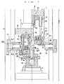
- Fig. 1 is a sectional view showing an embodiment of the cold deep hole forming device according to the present invention, the drawing in the right half showing the state in which the punch is raised and the drawing in the left half showing the state in which the punch is press fit in the member to be formed.
- Fig. 2 (A) is a sectional view showing a clamp holder in which is disposed a clamp, the drawing in the left half showing the state in which the outer circumference of the member to be formed is constrained with clamping pieces and the drawing in the right half showing the state in which that constraint is released.
- Fig. 2 (B) is a plan view showing the state of arrangement of clamping pieces.
- Fig. 3 indicates changes of BBD (Between Ball Diameter) from end face to inner part of a member to be formed of an involute spline formed on the member to be formed, (A) showing a case of forming made by using the cold deep hole forming device according to the present invention, and (B) showing a case of forming made by using a conventional cold deep hole forming device, respectively.
-
- The cold deep hole forming device according to the present invention will be explained hereafter with reference to drawings.
- Fig. 1 and Fig. 2 indicate an embodiment of the deep hole forming device according to the present invention.
- This cold deep hole forming device is constructed by comprising, for example, a supporting
base 1A for supporting the lower part of the member W to be formed partially different in thickness and apunch 1B for forming deep hole H for involute spline, etc. in this member W to be formed, and concentrically disposingclamp holder 3 on the outer circumference of thepunch 1B and also disposingclamp 2 composed by circumferentially disposing a plurality of splitclamping pieces 21 in thisclamp holder 3. - In this case, the supporting
base 1A is fixed on a base 4. - On the other hand, the
punch 1B is concentrically disposed over the supportingbase 1A, by providing apunch clamp holder 12, through amounting bracket 9, at the center position of alift stand 8 attached to aram 7, and fixing to thispunch clamp holder 12 by means of a box-nut shapedmounting fixture 13. - This makes it possible to lower the
punch 1B from above on the member W to be formed supported on the supportingbase 1A by driving theram 7, and form deep hole H for involute spline, etc. of prescribed shape in the member W to be formed, by press fitting thepunch 1B in the prepared hole H0 roughly formed in advance in the member W to be formed. - Moreover, the
clamp holder 3 is concentrically disposed on the outer circumference of thepunch 1B by hanging at the bottom end of a hangingbolt 11 guided in a way to go up and down by a supportingguide 10 disposed on the outer circumference of themounting bracket 9 attached to thelift stand 8. - On this
clamp holder 3 is placed aclamp 2 constructed by circumferentially disposing a plurality of splitclamping pieces 21. - In this embodiment, the
clamp 2 is composed ofclamping pieces 21 split into 8 parts, but the dividing number of theclamp 2 is not restricted to this number but may also be set for optional number such as 6 split parts, etc., for example. - The
clamping pieces 21 are disposed in aclamp holding mechanism 30 in circular shape formed by theclamp holder 3 and aflange 6 fixed to the bottom face of thisclamp holder 3 with abolt 6B. - This
clamp holding mechanism 30 is formed with a dimension D in axial direction (direction of height in Fig. 2 (A)) larger than the thickness T of theclamping pieces 21, and constructed in such a way that theclamping pieces 21 may move up and down in the range of a distance C in Fig. 2 (A) in theclamp holding mechanism 30. - In this case, the
clamping pieces 21 are arranged to be urged by a spring 3S1 interposed between theclamping pieces 21 and theflange 6. - Furthermore, to the
clamping pieces 21 is fastened abolt 3B which is inserted in aslit 3H provided in vertical direction in theclamp holder 3, to thereby prevent theclamping pieces 21 from circumferentially moving in theclamp holding mechanism 30, while a spring 3S2 disposed on the shaft of thebolt 3B keeps the outer side face 2T1 of theclamping pieces 21 in a state in contact with the innercircumferential face 3T of theclamp holder 3. - And, the outer side face 2T1 of the
clamping pieces 21 is formed on a downward slope face, and the innercircumferential face 3T of theclamp holder 3 to be in contact with the outer side face 2T1 of theclamping pieces 21 is also formed on a downward slope face. - Still more, at the top of the
clamp holder 3, forming aclamp holding mechanism 30, is formed anoperating fluid chamber 3R in circular shape, and disposed on apiston 5. - This makes it possible to feed operating fluid to the
operating fluid chamber 3R through aport 3P, when forming a deep hole H for involute spline, etc. in the member W to be formed supported on the supportingbase 1A bypunch 1B, to thereby move thepiston 5 in the downward direction in Fig. 2 (A), and move theclamping pieces 21 downward along the innercircumferential face 3T of theclamp holder 3 formed on a slope face, to the direction of the center, so as to constrain the outer circumference of the small diameter portion WT of the member W to be formed. - In case the supply of operating fluid to the
operating fluid chamber 3R is interrupted, theclamping pieces 21 move in the radial direction (direction to get away from the center), while moving upward along the innercircumferential face 3T of theclamp holder 3 formed on a slope face, under the action of the spring 3S1 interposed between theclamping pieces 21 and theflange 6 and the spring 3S2 disposed on the shaft of thebolt 3B fastened to theclamping pieces 21, thus making it possible to cancel the constraint byclamping pieces 21 on the outer circumference of the small diameter portion WT of the member W to be formed. - Yet more, on the body frame F is disposed a
stopper 14 for controlling ascent of theclamp holder 3 when theclamp holder 3 is at the down position. - This
stopper 14 is designed in such a way that, as operating fluid is fed to anoperating fluid chamber 14R formed inside thestopper body 14A fixed to the body frame F, thestopper pin 14P juts out and the tip of thestopper pin 14P is caught in thenotch 3K formed at the top of theclamp holder 3, to thereby control ascent of theclamp holder 3. - Thanks to this
stopper 14, it becomes possible to control ascent of theclamp holder 3, by engaging the tip of thestopper pin 14P with thenotch 3K formed at the top of theclamp holder 3, when extracting thepunch 1B from the member W to be formed by making theram 7 go up after forming a deep hole H for involute spline, etc. of prescribed shape in the member W to be formed with thepunch 1B, and extract thepunch 1B smoothly from the member W to be formed by preventing the member W to be formed from going up together with the clamp holder 3 (in this embodiment, the bottom face of theclamping pieces 21 disposed on theclamp 3 holder gets in contact with the member W to be formed). - The
stopper pin 14P is constructed in a way to be stored in thestopper body 14A, when the supply of operating fluid to theoperating fluid chamber 14R is stopped, under the action of thespring 14S disposed on the shaft of thestopper pin 14P, to allow ascent of theclamp holder 3 and its descent in the subsequent process. - The actions of the cold deep hole forming device according to the present invention will be explained hereafter.
- This member W to be formed, which is formed in prescribed shape in advance by the method of forging, etc., and having a prepared hole H0 roughly formed on it, is supported on a supporting
base 1A (right half drawing in Fig. 1). - Next, the
ram 7 is lowered, to thereby concentrically dispose theclamp holder 3 hung at the bottom end of the hangingbolt 11 guided in a way to go up and down by a supportingguide 10 disposed on the outer circumference of themounting bracket 9 attached to thelift stand 8, on the outer circumference of the small diameter portion WT of the member W to be formed. - In this state, operating fluid is fed to the
operating fluid chamber 3R of theclamp holder 3 through theport 3P, to thereby move thepiston 5 in the downward direction, and move theclamping pieces 21 downward along the innercircumferential face 3T of theclamp holder 3 formed on a slope face, to the direction of the center, so as to constrain the outer circumference of the small diameter portion WT of the member W to be formed (left half drawing in Fig. 2 (A)). - And, by further lowering the
ram 7, in the state in which the outer circumference of the small diameter portion WT of the member W to be formed is constrained by theclamping pieces 21, thepunch 1B is made to come down from above on the member W to be formed supported on the supportingbase 1A and press fit in the prepared hole H0 roughly formed in advance in the member W to be formed, to form a deep hole H for involute spline, etc. of prescribed shape in the member W to be formed with thepunch 1B (left half drawing in Fig. 1). - As described above, by forming deep hole H for involute spline, etc. of prescribed shape in the state in which the outer circumference of the small diameter portion WT of the member W to be formed is constrained, it becomes possible for form deep hole H for involute spline, etc. uniformly from end face to inner part of the member W to be formed even in the case where the member W to be formed is partially different in thickness.
- Fig. 3 (A) indicates changes of BBD (Between Ball Diameter) from end face to inner part of a member W to be formed of an involute spline formed by using the cold deep hole forming device according to the present invention, showing that the involute spline formed remains between the upper and lower limit values of BBD, in the range of effective length of the spline, thus ensuring high accuracy.
- And, as the supply of operating fluid to the
operating fluid chamber 3R is interrupted, theclamping pieces 21 move in the radial direction (direction to get away from the center), while moving upward along the innercircumferential face 3T of theclamp holder 3 formed on a slope face, under the action of the spring 3S1 interposed between theclamping pieces 21 and theflange 6 and the spring 3S2 disposed on the shaft of thebolt 3B fastened to theclamping pieces 21, to thereby cancel the constraint byclamping pieces 21 on the outer circumference of the small diameter portion WT of the member W to be formed (right half drawing in Fig. 2 (A)). - In this way, after forming deep hole H for involute spline, etc. of prescribed shape in the member W to be formed with the
punch 1B, theram 7 is made to go up to extract thepunch 1B from the member W to be formed. - At that time, as operating fluid is fed to the
operating fluid chamber 14R formed inside thestopper body 14A of thestopper 14 fixed to the body frame F, the tip of thestopper pin 14P is caught in thenotch 3K formed at the top of theclamp holder 3, to thereby control ascent of theclamp holder 3 and prevent the member W to be formed from going up, through theclamp holder 3, to extract thepunch 1B from the member W to be formed. - After extraction of the
punch 1B from the member W to be formed, the supply of operating fluid to theoperating fluid chamber 14R formed in thestopper body 14A of thestopper 14 is stopped, and thestopper pin 14P is stored in thestopper body 14A, to cancel control of ascent of theclamp holder 3, while theram 7 is raised to make theclamp holder 3 to go up and return to its initial state. - The member W to be formed in which is formed deep hole H for involute spline, etc. supported on the supporting
base 1A is taken out, to complete the forming process. - By the way, the shapes of the component parts such as supporting
base 1A,punch 1B andclamping pieces 21 composingclamp 2, etc. to be installed on this cold deep hole forming device are not restricted to those indicated in the present embodiment, but other shapes suitable to the shape of the member W to be formed may also be used as required. - In addition, the inner side face 2T2 of the
clamping pieces 21 to be in contact with the outer circumferential face of the small diameter portion WT of the member W to be formed may be formed on a slope, as required, thus making it possible to perform forming considering distortion produced on the formed pieces in the subsequent processes such as carbo-hardening, etc. to be made after the forming of the member W to be formed and obtain formed pieces of high accuracy. - Especially, in the case where the object member W to be formed is partially different in thickness as shown in Fig. 1 and Fig. 2, it is desirable to form in such a way that the end face side of the small diameter portion WT of the member W to be formed is slightly larger, to compensate for the distortion produced on the formed pieces in the subsequent processes such as carbo-hardening, etc. to be made after the forming of the member W to be formed, but this can be achieved easily by forming the inner side face 2T2 of the
clamping pieces 21 on a downward slope.
Claims (3)
- A cold deep hole forming device comprised of a support base (1A) to support the member (W) to be formed and a punch (1B) for forming a deep hole (H) in the member to be formed, characterised in that a clamp holder (3) is provided on the outer circumference of said punch (1B),
that a clamp (2) composed by circumferentially disposing a plurality of split clamping pieces (21) is disposed in said clamp holder (3), and
that, when forming a deep hole in the member (W) to be formed with said punch (18), said clamping pieces (21) are made to move in the direction of the center under fluid pressure, so as to constrain said member (W) to be formed at its outer circumference. - A cold deep hole forming device as defined in Claim 1, wherein the outer face of said clamping pieces (21) is formed on a sloped face, while the inner circumferential face of the clamp holder (3) with which the outer face of the clamping pieces (21) comes in contact is formed on a similar sloped face, to move said clamping pieces along the inner circumferential face of the clamp holder formed on the sloped face, through a fluid pressure piston (5), in the direction of the center.
- A cold deep hole forming device as defined in Claim 1 or 2, wherein the inner side face of the clamping pieces (21), to be in contact with the outer circumference of the member (W) to be formed, is formed on a sloped face.
Applications Claiming Priority (2)
| Application Number | Priority Date | Filing Date | Title |
|---|---|---|---|
| JP33030798A JP3519961B2 (en) | 1998-11-20 | 1998-11-20 | Cold deep hole forming equipment |
| JP33030798 | 1998-11-20 |
Publications (3)
| Publication Number | Publication Date |
|---|---|
| EP1002598A2 EP1002598A2 (en) | 2000-05-24 |
| EP1002598A3 EP1002598A3 (en) | 2001-08-29 |
| EP1002598B1 true EP1002598B1 (en) | 2003-05-02 |
Family
ID=18231183
Family Applications (1)
| Application Number | Title | Priority Date | Filing Date |
|---|---|---|---|
| EP99300496A Expired - Lifetime EP1002598B1 (en) | 1998-11-20 | 1999-01-22 | Device for cold-forming deep holes |
Country Status (4)
| Country | Link |
|---|---|
| US (1) | US6161415A (en) |
| EP (1) | EP1002598B1 (en) |
| JP (1) | JP3519961B2 (en) |
| DE (1) | DE69907373T2 (en) |
Families Citing this family (1)
| Publication number | Priority date | Publication date | Assignee | Title |
|---|---|---|---|---|
| RU2507025C2 (en) * | 2012-05-23 | 2014-02-20 | Открытое акционерное общество "Ижевский механический завод" | Method of making billet with variable-depth bottom and wall |
Family Cites Families (3)
| Publication number | Priority date | Publication date | Assignee | Title |
|---|---|---|---|---|
| US2027922A (en) * | 1935-05-29 | 1936-01-14 | Duro Metal Prod Co | Method of making wrench sockets |
| JPS5841643A (en) * | 1981-09-05 | 1983-03-10 | Kawasaki Yukou Kk | Closed-forging method |
| JPS6330142A (en) * | 1986-07-22 | 1988-02-08 | Musashi Seimitsu Ind Co Ltd | Manufacture of ball stud |
-
1998
- 1998-11-20 JP JP33030798A patent/JP3519961B2/en not_active Expired - Fee Related
-
1999
- 1999-01-22 EP EP99300496A patent/EP1002598B1/en not_active Expired - Lifetime
- 1999-01-22 DE DE69907373T patent/DE69907373T2/en not_active Expired - Lifetime
- 1999-03-16 US US09/270,014 patent/US6161415A/en not_active Expired - Lifetime
Also Published As
| Publication number | Publication date |
|---|---|
| EP1002598A3 (en) | 2001-08-29 |
| DE69907373D1 (en) | 2003-06-05 |
| JP2000158085A (en) | 2000-06-13 |
| DE69907373T2 (en) | 2004-04-01 |
| US6161415A (en) | 2000-12-19 |
| JP3519961B2 (en) | 2004-04-19 |
| EP1002598A2 (en) | 2000-05-24 |
Similar Documents
| Publication | Publication Date | Title |
|---|---|---|
| KR20110067640A (en) | Vent hole coining device on wheel disc | |
| JP3394332B2 (en) | Burring processing method | |
| EP1002598A2 (en) | Device for cold-forming deep holes | |
| EP1297911B1 (en) | Methods and apparatus for manufacturing flanged articles | |
| JP4930458B2 (en) | Spline forging apparatus and spline forging method | |
| JP5240510B2 (en) | Drawing machine | |
| JPS637857B2 (en) | ||
| JP3469275B2 (en) | Method and apparatus for manufacturing gear base material | |
| JP3514746B2 (en) | Bearing race forging method and bearing race separation device | |
| US5706697A (en) | Process of and apparatus for ironing work for bolt and the same work for bolt | |
| JP2009052511A (en) | Spring retainer for internal combustion engine and its manufacturing method | |
| JPS643615B2 (en) | ||
| JPH0661336U (en) | Metal molds for disk processing of automobile wheels | |
| JP4804292B2 (en) | Forging device for molded product having undercut part | |
| KR102960127B1 (en) | Press mold with integral frame structure for precious metal processing | |
| JPH10216893A (en) | Pipe flange processing apparatus and method | |
| CN216828261U (en) | Hardware stamping die with accurate positioning function | |
| JP2000326021A (en) | Punching mold | |
| JPH05212481A (en) | Molding device for cup-shaped product with spline having snap ring groove | |
| US7124484B1 (en) | Method of mounting precious stones | |
| JPS62114832A (en) | Gear manufacture and device thereof | |
| JP3003339U (en) | Metal mold for drawing and drawing up the mouth hole in a multi-process continuous mouth hole machine for metal can top plate | |
| RU2201835C2 (en) | Straightening die set | |
| SU1319994A1 (en) | Upsetting die | |
| JP2002001474A (en) | Gear shifting manufacturing equipment |
Legal Events
| Date | Code | Title | Description |
|---|---|---|---|
| PUAI | Public reference made under article 153(3) epc to a published international application that has entered the european phase |
Free format text: ORIGINAL CODE: 0009012 |
|
| AK | Designated contracting states |
Kind code of ref document: A2 Designated state(s): AT BE CH CY DE DK ES FI FR GB GR IE IT LI LU MC NL PT SE |
|
| AX | Request for extension of the european patent |
Free format text: AL;LT;LV;MK;RO;SI |
|
| PUAL | Search report despatched |
Free format text: ORIGINAL CODE: 0009013 |
|
| AK | Designated contracting states |
Kind code of ref document: A3 Designated state(s): AT BE CH CY DE DK ES FI FR GB GR IE IT LI LU MC NL PT SE |
|
| AX | Request for extension of the european patent |
Free format text: AL;LT;LV;MK;RO;SI |
|
| RIC1 | Information provided on ipc code assigned before grant |
Free format text: 7B 21J 5/12 A, 7B 21J 13/02 B |
|
| 17P | Request for examination filed |
Effective date: 20011016 |
|
| AKX | Designation fees paid |
Free format text: DE FR |
|
| GRAH | Despatch of communication of intention to grant a patent |
Free format text: ORIGINAL CODE: EPIDOS IGRA |
|
| GRAH | Despatch of communication of intention to grant a patent |
Free format text: ORIGINAL CODE: EPIDOS IGRA |
|
| GRAA | (expected) grant |
Free format text: ORIGINAL CODE: 0009210 |
|
| AK | Designated contracting states |
Designated state(s): DE FR |
|
| REF | Corresponds to: |
Ref document number: 69907373 Country of ref document: DE Date of ref document: 20030605 Kind code of ref document: P |
|
| ET | Fr: translation filed | ||
| PLBE | No opposition filed within time limit |
Free format text: ORIGINAL CODE: 0009261 |
|
| STAA | Information on the status of an ep patent application or granted ep patent |
Free format text: STATUS: NO OPPOSITION FILED WITHIN TIME LIMIT |
|
| 26N | No opposition filed |
Effective date: 20040203 |
|
| REG | Reference to a national code |
Ref country code: FR Ref legal event code: PLFP Year of fee payment: 18 |
|
| PGFP | Annual fee paid to national office [announced via postgrant information from national office to epo] |
Ref country code: FR Payment date: 20151127 Year of fee payment: 18 |
|
| PGFP | Annual fee paid to national office [announced via postgrant information from national office to epo] |
Ref country code: DE Payment date: 20160126 Year of fee payment: 18 |
|
| REG | Reference to a national code |
Ref country code: DE Ref legal event code: R119 Ref document number: 69907373 Country of ref document: DE |
|
| REG | Reference to a national code |
Ref country code: FR Ref legal event code: ST Effective date: 20170929 |
|
| PG25 | Lapsed in a contracting state [announced via postgrant information from national office to epo] |
Ref country code: FR Free format text: LAPSE BECAUSE OF NON-PAYMENT OF DUE FEES Effective date: 20170131 |
|
| PG25 | Lapsed in a contracting state [announced via postgrant information from national office to epo] |
Ref country code: DE Free format text: LAPSE BECAUSE OF NON-PAYMENT OF DUE FEES Effective date: 20170801 |