EP1002454A1 - Hydraulic circuit with a self-calibrating device for agricultural or earthmoving machinery. - Google Patents
Hydraulic circuit with a self-calibrating device for agricultural or earthmoving machinery. Download PDFInfo
- Publication number
- EP1002454A1 EP1002454A1 EP99203717A EP99203717A EP1002454A1 EP 1002454 A1 EP1002454 A1 EP 1002454A1 EP 99203717 A EP99203717 A EP 99203717A EP 99203717 A EP99203717 A EP 99203717A EP 1002454 A1 EP1002454 A1 EP 1002454A1
- Authority
- EP
- European Patent Office
- Prior art keywords
- hydraulic
- hydraulic circuit
- electrically operated
- control unit
- operated valve
- Prior art date
- Legal status (The legal status is an assumption and is not a legal conclusion. Google has not performed a legal analysis and makes no representation as to the accuracy of the status listed.)
- Granted
Links
Images

Classifications
-
- E—FIXED CONSTRUCTIONS
- E02—HYDRAULIC ENGINEERING; FOUNDATIONS; SOIL SHIFTING
- E02F—DREDGING; SOIL-SHIFTING
- E02F9/00—Component parts of dredgers or soil-shifting machines, not restricted to one of the kinds covered by groups E02F3/00 - E02F7/00
- E02F9/20—Drives; Control devices
- E02F9/2025—Particular purposes of control systems not otherwise provided for
-
- A—HUMAN NECESSITIES
- A01—AGRICULTURE; FORESTRY; ANIMAL HUSBANDRY; HUNTING; TRAPPING; FISHING
- A01B—SOIL WORKING IN AGRICULTURE OR FORESTRY; PARTS, DETAILS, OR ACCESSORIES OF AGRICULTURAL MACHINES OR IMPLEMENTS, IN GENERAL
- A01B71/00—Construction or arrangement of setting or adjusting mechanisms, of implement or tool drive or of power take-off; Means for protecting parts against dust, or the like; Adapting machine elements to or for agricultural purposes
- A01B71/02—Setting or adjusting mechanisms
-
- E—FIXED CONSTRUCTIONS
- E02—HYDRAULIC ENGINEERING; FOUNDATIONS; SOIL SHIFTING
- E02F—DREDGING; SOIL-SHIFTING
- E02F9/00—Component parts of dredgers or soil-shifting machines, not restricted to one of the kinds covered by groups E02F3/00 - E02F7/00
- E02F9/20—Drives; Control devices
- E02F9/22—Hydraulic or pneumatic drives
- E02F9/2221—Control of flow rate; Load sensing arrangements
- E02F9/2225—Control of flow rate; Load sensing arrangements using pressure-compensating valves
- E02F9/2228—Control of flow rate; Load sensing arrangements using pressure-compensating valves including an electronic controller
Definitions
- Self-calibrating device 11 also has the further advantage of being extremely cheap : manostat 12 is a low-cost component, while the alterations to electronic central control unit 4 are marginal and in essence are restricted to software modifications, and therefore are of negligible cost.
Abstract
Description
- The present invention relates to a hydraulic circuit with a self-calibrating device for agricultural or earthmoving machinery.
- As well known in the art, both agricultural and earthmoving machines comprise a hydraulic circuit for powering various vehicle-mounted devices, such as the steering assembly, differential, power transmission, shovel lifting and lowering assembly (if any), etc. The hydraulic circuit normally also comprises one or more hydraulic power take-off devices for temporarily connecting off-vehicle devices or implements having hydraulic motors and/or actuators to be driven by the hydraulic circuit of the vehicle.
- The hydraulic circuit currently comprises one or more electrically controlled hydraulic distributors which are supplied with a high-pressure fluid and, on command, distribute the fluid to the hydraulic power take-off devices. The circuit further comprises a variable-delivery pump for supplying the high-pressure fluid to the hydraulic distributors, and an electronic central control unit is operable to control the hydraulic distributors in order to regulate the flow of high-pressure fluid from the individual hydraulic power take-off devices.
- A major drawback of the above type of hydraulic circuit is the relatively high-cost maintenance involved.
- That is to say, each hydraulic distributor comprises one or more electrically operated valves for regulating flow to the hydraulic power take-off devices connected to the distributor. In view of the delicate task performed by the valves, the electronic central control unit is calibrated for each hydraulic device at the vehicle assembly stage to ensure that the high-pressure fluid supply set by the driver of the vehicle for whatever hydraulic power take-off device corresponds exactly with the high-pressure fluid actually supplied by said hydraulic power take-off device.
- Problems arise, however, when the electrically operated valves of the hydraulic distributor break down and need replacement. In this case, as opposed to simply replacing the valves, the entire hydraulic distributor must be replaced, and the electronic central control unit controlling the distributors must be re-calibrated. Moreover, calibrating the electronic central control unit is a highly skilled job which can only be carried out at the factory or specially equipped service centers, with obvious consequences in terms of cost.
- It is therefore an object of the present invention to provide a hydraulic circuit for agricultural or earthmoving machinery, designed to eliminate the aforementioned drawbacks.
- According to a first aspect of the present invention, there is provided a hydraulic circuit for agricultural or earthmoving machinery, comprising :
- at least one electrically controlled hydraulic distributor which is supplied with a high-pressure fluid and, on command, distributes said high-pressure fluid to at least one hydraulic power take-off;
- a pump unit for supplying the high-pressure fluid to said hydraulic distributor; and
- a control unit for controlling said electrically controlled hydraulic distributor to regulate the flow of high-pressure fluid through said hydraulic power take-off; said hydraulic distributor having at least one electrically operated valve for regulating the passage of the high-pressure fluid to said hydraulic power take-off. The hydraulic circuit is characterized in that it further comprises self-calibrating means for determining the response curve of said at least one electrically operated valve, and for calibrating said control unit on the basis of said response curve.
- According to a second aspect of the present invention there is provided a method of calibrating a hydraulic circuit for agricultural or earthmoving machinery.
- The method is characterized in that it comprises the steps of:
- supplying a gradually increasing current to a single electrically operated valve of an electrically controlled hydraulic distributor of said hydraulic circuit, any eventually other electrically operated valves being left de-energized;
- determining the electric current value at which said electrically operated valve begins to open; and
- determining, on the basis of said electric current value, the position, in a reference plane, of the response curve associated with said electrically operated valve.
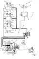
- A non-limiting embodiment of the present invention will now be described, by way of example, with reference to the accompanying drawings, in which:
- Figure 1 schematically shows a hydraulic circuit with a self-calibrating device for agricultural or earthmoving machinery, in accordance with the teachings of the present invention;
- Figure 2 shows a number of response curves of a component of the hydraulic circuit of Figure 1; and
- Figures 3 and 4 show time graphs of a number of variables of the Figure 1 hydraulic circuit during operation.
-
-
Number 1 in Figure 1 indicates as a whole a hydraulic circuit for agricultural or earthmoving machinery, for powering various on-vehicle devices (e.g. the steering assembly, the differential, the power transmission, etc.) and any other off-vehicle devices or implements connectable to the vehicle as required. -
Hydraulic circuit 1 comprises one or more electrically controlledhydraulic distributors 2, which are supplied with a high-pressure fluid (generally oil) and, on command, distribute the fluid to one or more user devices (not shown). Apump unit 3 is provided for supplying said high-pressure fluid to saidhydraulic distributors 2 and an electronic central control unit 4 is operable to control thehydraulic distributors 2 for regulating the supply of the high-pressure fluid to each user device as demanded by the driver of the vehicle. - In the example shown, driver demand is detected by electronic central control unit 4 via one or more known hand levers 14 operated by the driver of the vehicle and preferably, though not necessarily, located on the dashboard of the vehicle.
- Each
hydraulic distributor 2, of known type, comprises aninlet 2a through which the high-pressure fluid is fed thereto; one ormore outlets 2b through which the high-pressure fluid flows out on command; and one or more electrically operatedvalves 5 for regulating the flow of the high-pressure fluid frominlet 2a tooutlets 2b. -
Outlets 2b ofhydraulic distributors 2 each communicate with a respective hydraulic power take-off 6 ofhydraulic circuit 1. The above mentioned user devices, i.e. off-vehicle devices or implements, are connectable to said hydraulic power take-offs 6 to power the hydraulic motors and/or actuators of the devices or implements by means ofhydraulic circuit 1. - Electronic central control unit 4 drives electrically operated
valves 5 to regulate high-pressure fluid flow to each hydraulic power take-off 6 as demanded by the driver of the vehicle, i.e. on the basis of the position of hand lever(s) 14. -
Hydraulic distributor 2 further comprises anauxiliary outlet 2c through which high-pressure fluid flows out at a pressure depending on the flow of high-pressure fluid tooutlets 2b of the distributor. - With reference to Figure 1,
pump unit 3 is of a conventional type, and comprises a variable-delivery pump 7, the displacement of which is regulated by ahydraulic actuator 7a controlled by the high-pressure fluid fromauxiliary outlets 2c ofhydraulic distributors 2. -
Auxiliary outlets 2c in fact are connected tohydraulic actuator 7a ofpump 7 by a feedback or so-called load-sensing conduit 8. In the example shown, feedback conduit 8 ofhydraulic circuit 1 comprises a number ofnon-return valves 9 located along the branches extending from feedback conduit 8 to respectiveauxiliary outlets 2c. The conduit 8 further comprises a regulating or so-called load-sensingvalve 10 for supplying the hydraulic actuator ofpump 7 with a quantity of high-pressure fluid depending on the amount of fluid delivered bypump 7 and on the amount of fluid delivered fromauxiliary outlets 2c. Regulatingvalve 10 is located along the main portion of feedback conduit 8, immediately upstream of the hydraulic actuator ofpump 7, and is defined by a conventional flow compensating valve and a conventional pressure compensating valve connected to each other in a cascade-like manner. - In accordance with the present invention,
hydraulic circuit 1 further comprises a self-calibrating device 11 for determining the response curve Q(I) of each electrically operatedvalve 5, and for calibrating electronic central control unit 4 so that the fluid supply set by the driver of the vehicle for whichever of the hydraulic power take-offs 6 always exactly corresponds with the high-pressure fluid actually supplied by the actuated hydraulic power take-off 6. - With reference to Figure 2, as is known, electrically operated
valves 5 ofhydraulic distributors 2 all have a substantially similar flow-current response curve Q(I). However, due to manufacturing tolerances, the position of the response curve in the reference plane varies from one valve to another. In the example shown, the variation is caused by different values of current Io, at whichvalve 5 begins to open, i.e. at which fluid starts flowing throughoutlet 2b. - With reference to Figure 1, the self-calibrating
device 11 is activated by the driver of the vehicle, e.g. by means of a push-button 13. Thedevice 11 comprises the electronic central control unit 4, or rather a portion of it, and amanostat 12 located along feedback conduit 8, upstream from regulatingvalve 10.Manostat 12, which may be replaced by a known pressure switch, is connected to electronic central control unit 4, and is operable to monitor, instant by instant, the pressure of the fluid in feedback conduit 8, whereby any variation in pressure is detected. - Operation of
hydraulic circuit 1 and associated self-calibratingdevice 11 will now be described assuming that self-calibratingdevice 11 has just been activated by the driver of the vehicle by pressing the push-button 13, and that no user devices are connected to the hydraulic power take-offs 6. Under these operating conditions, a minimum quantity of high-pressure fluid is circulated inhydraulic circuit 1 bypump 7 to keephydraulic circuit 1 full and ready to perform as commanded by the driver. - In actual use, with hydraulic power take-
offs 6 closed, the electronic central control unit 4 gradually begins to increase from zero the current circulating in one of the electrically operatedvalves 5, while leaving the other valves de-energized. With reference to Figures 3 and 4, as the electric current increases gradually and as long asvalve 5 remains closed,manostat 12 detects a pressure of value P1 (normally about 20 bars). - At instant to, the electric current circulating in
valve 5 reaches a value Io sufficient to startopening valve 5, while the pressure of the fluid in feedback conduit 8 switches, with a substantial stepped change, from value P1 to a much higher value P2 (of about 200 bars). The step pattern of the pressure change of the fluid in feedback conduit 8 under the above operating conditions is widely known. - By means of
manostat 12, the electronic central control unit 4 thus detects whenvalve 5 starts opening, internally memorizes current value Io, and immediately determines the position, in the reference plane, of the response curve Q(I) associated withvalve 5. Ifmanostat 12 is replaced by a pressure switch, electronic central control unit 4 detects the opening ofvalve 5 when the switch trips. The pressure switch must of course be set to trip when the pressure exceeds a threshold value between pressure values P1 and P2 (e.g. 120 bars). - Having determined the current value Io for a
first valve 5, the electronic central control unit 4 de-energizes saidvalve 5 and commences the above calibration procedure for a second one of thevalves 5. By determining a new current value I'o for saidsecond valve 5, the position, in the reference plane, of the response curve Q(I) of saidsecond valve 5, can be determined in a similar manner as with thefirst valve 5. - By repeating the calibration procedure for all
valves 5 of all thehydraulic distributors 2, electronic central control unit 4 determines the position, in the reference plane, of the response curves Q(I) of all thevalves 5, and is therefore able to supply eachvalve 5 with electric current of such a value as to obtain the exact high-pressure fluid flow requested by the driver of the vehicle. - In other words, electronic central control unit 4 is capable of calibrating itself so that the fluid supply demanded by the driver of the vehicle for any one of the hydraulic power take-
offs 6 always corresponds exactly with the high-pressure fluid actually supplied to the take-off. - Besides the obvious advantage of eliminating re-calibration of the electronic central control unit 4 in a plant whenever a
hydraulic distributor 2 is repaired, self-calibratingdevice 11 also provides for faster initial calibration of electronic central control unit 4 during manufacture of the vehicle, thus reducing production costs. - Self-calibrating
device 11 also has the further advantage of being extremely cheap :manostat 12 is a low-cost component, while the alterations to electronic central control unit 4 are marginal and in essence are restricted to software modifications, and therefore are of negligible cost. - Clearly, changes may be made to
hydraulic circuit 1 as described and illustrated herein without, however, departing from the scope of the present invention.
Claims (10)
- A hydraulic circuit (1) for agricultural or earthmoving machinery, comprising :at least one electrically controlled hydraulic distributor (2) which is supplied with a high-pressure fluid and, on command, distributes said high-pressure fluid to at least one hydraulic power take-off (6);a pump unit (3) for supplying the high-pressure fluid to said hydraulic distributor (2); anda control unit (4) for controlling said electrically controlled hydraulic distributor (2) to regulate the flow of high-pressure fluid through said hydraulic power take-off (6); said hydraulic distributor (2) having at least one electrically operated valve (5) for regulating the passage of the high-pressure fluid to said hydraulic power take-off (6); and
characterized in that said hydraulic circuit (1) further comprises self-calibrating means (11) for determining the response curve (Q(I)) of said at least one electrically operated valve (5), and for calibrating said control unit (4) on the basis of said response curve (Q(I)). - A hydraulic circuit according to claim 1, characterized in that :said pump unit (3) comprises a variable-displacement pump (7); andsaid hydraulic distributor (2) regulates the delivery of said variable-displacement pump (7) by means of a fluid flow returned to said variable-displacement pump (7) through a feedback conduit (8); said self-calibrating means (11) comprising detecting means (12) for detecting variations in the pressure of the fluid in said feedback conduit (8).
- A hydraulic circuit according to claim 2, characterized in that said detecting means (12) for detecting variations in the pressure of the fluid in said feedback conduit (8) comprises a manostat (12) located along said feedback conduit (8).
- A hydraulic circuit according to claim 2, characterized in that said detecting means (12) for detecting variations in the pressure of the fluid in said feedback conduit (8) comprises a pressure switch located along said feedback conduit (8).
- A hydraulic circuit according to claim 2 and any claim depending therefrom, characterized in that said self-calibrating means (11) comprises an electronic central control unit (4) connected to said detecting means (12); said electronic central control unit (4) being operable, in succession, to supply the electrically operated valve (5) of the hydraulic distributor (2) with a gradually increasing current, and to determine, in co-operation with said detecting means (12), the electric current value (Io) at which the electrically operated valve (5) begins opening; the electronic central control unit (4) also determining, on the basis of said electric current value (Io), the position, in a reference plane, of the response curve (Q(I)) associated with said electrically operated valve (5).
- A hydraulic circuit according to claim 5, characterized in that said control unit (4) comprises the electronic central control unit (4) of said self-calibrating means (11).
- A hydraulic circuit according to any of the preceding claims, characterized in that the operation of said self-calibrating means (11) is initiated by the driver of the vehicle.
- A method of calibrating a hydraulic circuit (1) for agricultural or earthmoving machinery, and
characterized in that the method comprises the steps of:supplying a gradually increasing current to a single electrically operated valve (5) of an electrically controlled hydraulic distributor (2) of said hydraulic circuit (1), any eventually other electrically operated valves (5) being left de-energized;determining the electric current value (Io) at which said electrically operated valve (5) begins to open; anddetermining, on the basis of said electric current value (Io), the position, in a reference plane, of the response curve (Q(I)) associated with said electrically operated valve (5). - A method according to claim 8, characterized in that the step of determining the electric current value (Io) at which the electrically operated valve (5) begins to open comprises the step of detecting a substantial stepped change in the pressure of a fluid in a feedback conduit (8) of said hydraulic circuit (1).
- A method according to claims 8 or 9, characterized in that said step of supplying a gradually increasing current to one electrically operated valve (5) of the hydraulic distributor (2) is performed with the hydraulic power take-offs (6) of the hydraulic circuit (1) closed.
Applications Claiming Priority (2)
| Application Number | Priority Date | Filing Date | Title |
|---|---|---|---|
| IT1998BO000642A IT1303971B1 (en) | 1998-11-18 | 1998-11-18 | HYDRAULIC CIRCUIT FOR AGRICULTURAL MACHINES OR EARTH MOVEMENT CONDITIONING OF SELF-CALIBRATION AND RELATED OPERATING METHOD. |
| ITBO980642 | 1998-11-18 |
Publications (2)
| Publication Number | Publication Date |
|---|---|
| EP1002454A1 true EP1002454A1 (en) | 2000-05-24 |
| EP1002454B1 EP1002454B1 (en) | 2003-09-03 |
Family
ID=11343512
Family Applications (1)
| Application Number | Title | Priority Date | Filing Date |
|---|---|---|---|
| EP99203717A Expired - Lifetime EP1002454B1 (en) | 1998-11-18 | 1999-11-08 | Hydraulic circuit with a self-calibrating device for agricultural or earthmoving machinery. |
Country Status (4)
| Country | Link |
|---|---|
| US (1) | US6347517B1 (en) |
| EP (1) | EP1002454B1 (en) |
| DE (1) | DE69910948T2 (en) |
| IT (1) | IT1303971B1 (en) |
Cited By (3)
| Publication number | Priority date | Publication date | Assignee | Title |
|---|---|---|---|---|
| EP1561951A2 (en) * | 2004-02-03 | 2005-08-10 | Jungheinrich Aktiengesellschaft | Method for adjusting the control current of hydraulic solenoid valves |
| WO2008027169A1 (en) * | 2006-08-31 | 2008-03-06 | Caterpillar Inc. | Method for calibrating independent metering valves |
| CN102725542A (en) * | 2009-11-30 | 2012-10-10 | 伊顿公司 | Out-of-range sensor recalibration |
Families Citing this family (9)
| Publication number | Priority date | Publication date | Assignee | Title |
|---|---|---|---|---|
| US7017674B2 (en) * | 2003-11-17 | 2006-03-28 | Caterpillar Inc. | Method of changing operating characteristics of an implement |
| US8403098B2 (en) * | 2005-02-28 | 2013-03-26 | Caterpillar Inc. | Work machine hydraulics control system |
| US7392790B2 (en) * | 2006-01-20 | 2008-07-01 | Caterpillar Inc. | System and method for resolving crossed electrical leads |
| US7370635B2 (en) * | 2006-01-20 | 2008-05-13 | Caterpillar Inc. | System and method for resolving electrical leads |
| US7798272B2 (en) * | 2006-11-30 | 2010-09-21 | Caterpillar Inc | Systems and methods for controlling slip of vehicle drive members |
| US8374766B2 (en) * | 2007-11-29 | 2013-02-12 | Caterpillar Paving Products Inc. | Power management system for compaction vehicles and method |
| US7849953B2 (en) * | 2007-11-29 | 2010-12-14 | Caterpillar Paving Products Inc | Control system and method for operating a hydrostatically driven vehicle |
| US11180184B2 (en) | 2019-01-25 | 2021-11-23 | Cnh Industrial America Llc | Automatic steering calibration of an agricultural machine |
| DE102021003236A1 (en) * | 2021-06-23 | 2022-12-29 | Hydac Fluidtechnik Gmbh | Method for adapting a control of a proportional valve to its functional operation as part of a fluid system |
Citations (6)
| Publication number | Priority date | Publication date | Assignee | Title |
|---|---|---|---|---|
| US4879662A (en) * | 1988-03-11 | 1989-11-07 | Sundstrand Corporation | Fluid flow self calibration scheme |
| US4980825A (en) * | 1988-05-11 | 1990-12-25 | Hydro-Craft, Inc. | Servo valve analyzing system and method |
| US5012415A (en) * | 1989-01-06 | 1991-04-30 | Deere & Company | Control system calibration |
| US5472056A (en) * | 1993-09-08 | 1995-12-05 | Case Corporation | Control system for agricultural vehicle and calibration method for such control systems |
| EP0786200A2 (en) * | 1996-01-27 | 1997-07-30 | Robert Bosch Gmbh | Agricultural machine working unit position regulation device |
| US5784945A (en) * | 1997-05-14 | 1998-07-28 | Caterpillar Inc. | Method and apparatus for determining a valve transform |
Family Cites Families (3)
| Publication number | Priority date | Publication date | Assignee | Title |
|---|---|---|---|---|
| DE3644736C2 (en) * | 1985-12-30 | 1996-01-11 | Rexroth Mannesmann Gmbh | Control arrangement for at least two hydraulic consumers fed by at least one pump |
| US5762475A (en) * | 1996-03-18 | 1998-06-09 | Caterpillar Inc. | Automatic solenoid control valve calibration |
| US5844390A (en) * | 1997-01-27 | 1998-12-01 | Cameron; Robert | Method and apparatus for regulating a fluid operated machine |
-
1998
- 1998-11-18 IT IT1998BO000642A patent/IT1303971B1/en active
-
1999
- 1999-11-08 DE DE69910948T patent/DE69910948T2/en not_active Expired - Lifetime
- 1999-11-08 EP EP99203717A patent/EP1002454B1/en not_active Expired - Lifetime
- 1999-11-12 US US09/439,262 patent/US6347517B1/en not_active Expired - Lifetime
Patent Citations (6)
| Publication number | Priority date | Publication date | Assignee | Title |
|---|---|---|---|---|
| US4879662A (en) * | 1988-03-11 | 1989-11-07 | Sundstrand Corporation | Fluid flow self calibration scheme |
| US4980825A (en) * | 1988-05-11 | 1990-12-25 | Hydro-Craft, Inc. | Servo valve analyzing system and method |
| US5012415A (en) * | 1989-01-06 | 1991-04-30 | Deere & Company | Control system calibration |
| US5472056A (en) * | 1993-09-08 | 1995-12-05 | Case Corporation | Control system for agricultural vehicle and calibration method for such control systems |
| EP0786200A2 (en) * | 1996-01-27 | 1997-07-30 | Robert Bosch Gmbh | Agricultural machine working unit position regulation device |
| US5784945A (en) * | 1997-05-14 | 1998-07-28 | Caterpillar Inc. | Method and apparatus for determining a valve transform |
Cited By (7)
| Publication number | Priority date | Publication date | Assignee | Title |
|---|---|---|---|---|
| EP1561951A2 (en) * | 2004-02-03 | 2005-08-10 | Jungheinrich Aktiengesellschaft | Method for adjusting the control current of hydraulic solenoid valves |
| EP1561951A3 (en) * | 2004-02-03 | 2005-11-30 | Jungheinrich Aktiengesellschaft | Method for adjusting the control current of hydraulic solenoid valves |
| WO2008027169A1 (en) * | 2006-08-31 | 2008-03-06 | Caterpillar Inc. | Method for calibrating independent metering valves |
| US7562554B2 (en) | 2006-08-31 | 2009-07-21 | Caterpillar Inc. | Method for calibrating independent metering valves |
| CN101517245B (en) * | 2006-08-31 | 2012-07-25 | 卡特彼勒公司 | Method and system for calibrating independent metering valves |
| CN102725542A (en) * | 2009-11-30 | 2012-10-10 | 伊顿公司 | Out-of-range sensor recalibration |
| CN102725542B (en) * | 2009-11-30 | 2014-11-12 | 伊顿公司 | Out-of-range sensor recalibration method and system and method of recovering machine operation |
Also Published As
| Publication number | Publication date |
|---|---|
| EP1002454B1 (en) | 2003-09-03 |
| ITBO980642A0 (en) | 1998-11-18 |
| DE69910948T2 (en) | 2004-05-19 |
| US6347517B1 (en) | 2002-02-19 |
| IT1303971B1 (en) | 2001-03-01 |
| ITBO980642A1 (en) | 2000-05-18 |
| DE69910948D1 (en) | 2003-10-09 |
Similar Documents
| Publication | Publication Date | Title |
|---|---|---|
| US6347517B1 (en) | Hydraulic circuit with a self-calibrating device for agricultural or earthmoving machinery | |
| US7089733B1 (en) | Hydraulic control valve system with electronic load sense control | |
| EP0773370B1 (en) | Hydraulic controller | |
| EP1760325B1 (en) | Hydraulic load sensing system for agricultural tractors | |
| CN109139577B (en) | Valve block device and method for a valve block device | |
| US5535587A (en) | Hydraulic drive system | |
| EP0768433B1 (en) | Control circuit for a construction machine | |
| EP0504415B1 (en) | Control system of hydraulic pump | |
| US20070251755A1 (en) | Hydraulic steering | |
| EP1020648B1 (en) | Method and device for controlling work machine | |
| KR20010098914A (en) | A self-calibrating system and method for controlling a hydraulically operated device | |
| EP0864699B1 (en) | Hydraulic control system for construction machine | |
| EP2964963B1 (en) | Pilot pressure control system | |
| EP0746491B1 (en) | A hydraulic control system for work vehicles | |
| CN109154153B (en) | Safety system for construction machine | |
| EP3431783B1 (en) | Load-dependent hydraulic fluid flow control system | |
| KR20120099682A (en) | Method of operating a control valve assembly for a hydraulic system | |
| US6581717B1 (en) | Hydraulic steering arrangement | |
| DE10047631A1 (en) | Hydraulic system for battery-operated electric load conveying vehicle has hydraulic unit acting as pump and motor coupled to electrical unit acting as motor and generator | |
| US5829251A (en) | Hydraulic control circuit for working components, in particular in earth-moving machines | |
| KR20200065597A (en) | Automatic steering system for agricultural machinery | |
| KR920008658Y1 (en) | Oil-pressure control device of excavator | |
| EP0433454B1 (en) | Hydraulic circuit apparatus | |
| US10920396B1 (en) | Hydraulic system for a motor grader | |
| EP3243965B1 (en) | Controlling an electric proportional valve |
Legal Events
| Date | Code | Title | Description |
|---|---|---|---|
| PUAI | Public reference made under article 153(3) epc to a published international application that has entered the european phase |
Free format text: ORIGINAL CODE: 0009012 |
|
| AK | Designated contracting states |
Kind code of ref document: A1 Designated state(s): DE FR GB IT |
|
| AX | Request for extension of the european patent |
Free format text: AL;LT;LV;MK;RO;SI |
|
| 17P | Request for examination filed |
Effective date: 20001114 |
|
| AKX | Designation fees paid |
Free format text: DE FR GB IT |
|
| 17Q | First examination report despatched |
Effective date: 20021025 |
|
| RAP1 | Party data changed (applicant data changed or rights of an application transferred) |
Owner name: CNH ITALIA S.P.A. |
|
| GRAH | Despatch of communication of intention to grant a patent |
Free format text: ORIGINAL CODE: EPIDOS IGRA |
|
| GRAS | Grant fee paid |
Free format text: ORIGINAL CODE: EPIDOSNIGR3 |
|
| GRAA | (expected) grant |
Free format text: ORIGINAL CODE: 0009210 |
|
| AK | Designated contracting states |
Kind code of ref document: B1 Designated state(s): DE FR GB IT |
|
| REG | Reference to a national code |
Ref country code: GB Ref legal event code: FG4D |
|
| REF | Corresponds to: |
Ref document number: 69910948 Country of ref document: DE Date of ref document: 20031009 Kind code of ref document: P |
|
| ET | Fr: translation filed | ||
| PLBE | No opposition filed within time limit |
Free format text: ORIGINAL CODE: 0009261 |
|
| STAA | Information on the status of an ep patent application or granted ep patent |
Free format text: STATUS: NO OPPOSITION FILED WITHIN TIME LIMIT |
|
| 26N | No opposition filed |
Effective date: 20040604 |
|
| REG | Reference to a national code |
Ref country code: DE Ref legal event code: R082 Ref document number: 69910948 Country of ref document: DE Representative=s name: G. KOCH UND KOLLEGEN, DE |
|
| REG | Reference to a national code |
Ref country code: DE Ref legal event code: R082 Ref document number: 69910948 Country of ref document: DE Representative=s name: G. KOCH UND KOLLEGEN, DE Effective date: 20140623 Ref country code: DE Ref legal event code: R081 Ref document number: 69910948 Country of ref document: DE Owner name: CNH INDUSTRIAL ITALIA S.P.A., IT Free format text: FORMER OWNER: CNH ITALIA S.P.A., MODENA, IT Effective date: 20140623 |
|
| REG | Reference to a national code |
Ref country code: FR Ref legal event code: CD Owner name: CNH INDUSTRIAL ITALIA S.P.A. Effective date: 20150313 |
|
| REG | Reference to a national code |
Ref country code: DE Ref legal event code: R084 Ref document number: 69910948 Country of ref document: DE |
|
| REG | Reference to a national code |
Ref country code: FR Ref legal event code: PLFP Year of fee payment: 17 |
|
| REG | Reference to a national code |
Ref country code: GB Ref legal event code: 746 Effective date: 20150928 |
|
| PGFP | Annual fee paid to national office [announced via postgrant information from national office to epo] |
Ref country code: IT Payment date: 20151104 Year of fee payment: 17 |
|
| REG | Reference to a national code |
Ref country code: FR Ref legal event code: PLFP Year of fee payment: 18 |
|
| PGFP | Annual fee paid to national office [announced via postgrant information from national office to epo] |
Ref country code: DE Payment date: 20161014 Year of fee payment: 18 Ref country code: GB Payment date: 20161006 Year of fee payment: 18 Ref country code: FR Payment date: 20161010 Year of fee payment: 18 |
|
| PG25 | Lapsed in a contracting state [announced via postgrant information from national office to epo] |
Ref country code: IT Free format text: LAPSE BECAUSE OF NON-PAYMENT OF DUE FEES Effective date: 20161108 |
|
| REG | Reference to a national code |
Ref country code: DE Ref legal event code: R119 Ref document number: 69910948 Country of ref document: DE |
|
| GBPC | Gb: european patent ceased through non-payment of renewal fee |
Effective date: 20171108 |
|
| REG | Reference to a national code |
Ref country code: FR Ref legal event code: ST Effective date: 20180731 |
|
| PG25 | Lapsed in a contracting state [announced via postgrant information from national office to epo] |
Ref country code: FR Free format text: LAPSE BECAUSE OF NON-PAYMENT OF DUE FEES Effective date: 20171130 Ref country code: DE Free format text: LAPSE BECAUSE OF NON-PAYMENT OF DUE FEES Effective date: 20180602 |
|
| PG25 | Lapsed in a contracting state [announced via postgrant information from national office to epo] |
Ref country code: GB Free format text: LAPSE BECAUSE OF NON-PAYMENT OF DUE FEES Effective date: 20171108 |