EP1002350B1 - Surge arrester having disconnector housed by end cap - Google Patents
Surge arrester having disconnector housed by end cap Download PDFInfo
- Publication number
- EP1002350B1 EP1002350B1 EP98923871A EP98923871A EP1002350B1 EP 1002350 B1 EP1002350 B1 EP 1002350B1 EP 98923871 A EP98923871 A EP 98923871A EP 98923871 A EP98923871 A EP 98923871A EP 1002350 B1 EP1002350 B1 EP 1002350B1
- Authority
- EP
- European Patent Office
- Prior art keywords
- surge
- arrester
- end cap
- housing
- arresting element
- Prior art date
- Legal status (The legal status is an assumption and is not a legal conclusion. Google has not performed a legal analysis and makes no representation as to the accuracy of the status listed.)
- Expired - Lifetime
Links
Images


Classifications
-
- H—ELECTRICITY
- H01—ELECTRIC ELEMENTS
- H01T—SPARK GAPS; OVERVOLTAGE ARRESTERS USING SPARK GAPS; SPARKING PLUGS; CORONA DEVICES; GENERATING IONS TO BE INTRODUCED INTO NON-ENCLOSED GASES
- H01T1/00—Details of spark gaps
- H01T1/14—Means structurally associated with spark gap for protecting it against overload or for disconnecting it in case of failure
-
- H—ELECTRICITY
- H01—ELECTRIC ELEMENTS
- H01C—RESISTORS
- H01C7/00—Non-adjustable resistors formed as one or more layers or coatings; Non-adjustable resistors made from powdered conducting material or powdered semi-conducting material with or without insulating material
- H01C7/10—Non-adjustable resistors formed as one or more layers or coatings; Non-adjustable resistors made from powdered conducting material or powdered semi-conducting material with or without insulating material voltage responsive, i.e. varistors
- H01C7/12—Overvoltage protection resistors; Arresters
Definitions
- the present invention relates to a surge arrester for shunting electrical surges to ground. More particularly, the surge arrester of the present invention may have a disconnector which disconnects the surge arrester from ground in the event of a failure of the surge arrester.
- US Patent No. 4 404 614 which is considered to represent the closest prior art, discloses a surge arrester including an outer elongated housing and an inner liner.
- the outer housing is constructed of a material which will not break as a result of internal electrical arcing, specifically a relatively resilient, electrically insulating and non-tracking material which in a preferred embodiment is EPDM rubber.
- its inner line is constructed of a high strength material, preferably resin impregnated fibreglass.
- That arrester has a housing having a conductive plug at one end, a ground disconnector in the form of a pressure relief valve at the other end, and a number of valve elements, a gap assembly, and a spring within the housing between the conductive plug and the pressure relieve valve which includes a cup and a diaphragm.
- Overvoltage surges which travel along an electric power distribution system and which are not properly averted or diverted, often damage transformers and other electrical equipment of the electric power distribution system, as well as the electrical equipment of residential, commercial and industrial customers supplied by the electric power distribution system. Consequently, surge arresters are commonly used in an electric power distribution system for shunting overvoltage surges to system ground before the overvoltage surges can damage the electrical equipment connected in, or to, the electric power distribution system.
- Typical surge arresters used in electric power distribution systems can fail in a runaway condition. When such a failure occurs, the surge arrester may explode apart, potentially damaging nearby equipment and injuring anyone who happens to be near. Therefore, it has been a common prior art practice to provide surge arresters with fault disconnectors which open the circuits containing failed surge arresters.
- a fault disconnector is connected between its corresponding surge arrester and ground so that, when the fault disconnector activates upon failure of the surge arrester, the fault disconnector separates the surge arrester from its ground connection. The separated ground connection not only disconnects the failed surge arrester from the electric power distribution system, but also provides a visible indication to a utility linesmen that the surge arrester has failed.
- a typical fault disconnector includes a cartridge, which may contain a predetermined amount of gun powder, and which is heated as the surge arrester begins to fail. When the cartridge heats sufficiently, it explodes separating the surge arrester from its ground connection. The amount of gun powder that is used in the cartridge is sufficient to cause such separation but not sufficient to cause damage or injury.
- the cartridge, and the other elements of the fault disconnector are contained within a disconnector housing that is a separate component of the surge arrester, that has an internally threaded hole for threaded attachment to a housing of the surge arrester, and that has an external threaded ground connector for attachment to a ground lead.
- An electrical resistor which is another element of the fault disconnector and which is housed by the disconnector housing, is electrically connected between a surge arrester terminal and the ground connector of the disconnector. Accordingly, when the surge arrester fails, the current through the electrical resistor increases abnormally and generates enough heat to trigger the cartridge causing it to break the disconnector housing and to separate the ground terminal from the surge arrester.
- the use of a separate disconnector housing increases the part count of a surge arrester which, in turn, increases the manufacturing cost of the surge arrester.
- the present invention is directed to a surge arrester which reduces part count.
- the present invention provides a surge arrester as defined in claim 1 hereof.
- Other, preferred, features of the invention are defined in subsidiary claims.
- a surge arrester 10 includes a first terminal end 12 and a second terminal end 14.
- the first terminal end 12 includes a first connector 16 which is used to electrically connect the surge arrester 10 to a first electrical line.
- the second terminal end 14 includes a second connector 18 which is used to electrically connect the surge arrester 10 to a second electrical line.
- the first electrical line may be, for example, an electrically conducting lead which connects the first connector 16 to a high voltage line of an electrical power distribution system
- the second electrical line may be an electrically conducting lead which connects the second connector 18 to ground.
- the first electrical line may be, for example, an electrically conducting lead which connects the first connector 16 to ground
- the second electrical line may be an electrically conducting lead which connects the second connector 18 to a high voltage line of an electrical power distribution system.
- the first connector 16 is threaded into a first end cap 20, and the second connector 18 is electrically connected to a second end cap 22 in a manner to be described below.
- the first and second end caps 20 and 22 are electrically conductive and, for example, may be formed from aluminum.
- a first surge arresting element 24 is in electrical contact with the first end cap 20, a second surge arresting element 26 is in electrical contact with the first surge arresting element 24, a third surge arresting element 28 is in electrical contact with the second surge arresting element 26, and a fourth surge arresting element 30 is in electrical contact with both the third surge arresting element 28 and the second end cap 22. Accordingly, a series circuit is formed between the first and second end caps 20 and 22.
- the surge arresting elements 24-30 may be metal oxide varistor blocks, for example, which conduct in the presence of surges in order to shunt the surge energy in the electric power distribution system between the first and second connectors 16 and 18.
- An arrester housing 32 houses the first and second end caps 20 and 22 and the surge arresting elements 24, 26, 28, and 30.
- the arrester housing 32 may be an insulating polymeric or porcelain housing having a plurality of polymeric or porcelain water sheds 34.
- a mounting bracket 36 is provided in order to mount and support the surge arrester 10 to a utility pole or other apparatus of an electric power distribution system.
- the second end cap 22 has a first end 40 which is in electrical contact with the fourth surge arresting element 30.
- the second end cap 22 also has a second end 42 which comprises a wall 44 forming a recess 46.
- a fault disconnector 47 includes a cartridge 48 which is contained within an end 50 of the second connector 18.
- the fault disconnector 47 also includes a first electrically conductive washer 52 abutting the end 50 of the second connector 18, a second electrically conductive washer 54 abutting an internal wall 58 of the second end cap 22, and a resistor 56 sandwiched between the first and second electrically conductive washers 52 and 54.
- a plastic cup 59 contains the first and second electrically conductive washers 52 and 54 and the resistor 56 when the fault disconnector 47 is assembled as shown in Figure 1.
- the plastic cup 59 insulates the resistor 56 and the first and second electrically conductive washers 52 and 54 from the wall 44 of the second end cap 22 forcing fault current to flow from the second end cap 22 through the second electrically conductive washer 54, through the resistor 56, through the first electrically conductive washer 52, and through the second connector 18.
- the wall 44 of the second end cap 22 has a circumferential groove 60 therearound.
- the surge arresting elements 24, 26, 28, and 30 are stacked between the first and second end caps 20 and 22.
- the stack formed by the surge arresting elements 24, 26, 28, and 30 and the first and second end caps 20 and 22 is wrapped with a fiber glass weave in order to retain the surge arresting elements 24, 26, 28, and 30 and the first and second end caps 20 and 22 in the stack.
- the arrester housing 32 is applied to the wrapped stack of the surge arresting elements 24, 26, 28, and 30 and the first and second end caps 20 and 22 as shown in Figure 1.
- the arrester housing 32 may be molded directly on the wrapped stack of the surge arresting elements 24, 26, 28, and 30 and the first and second end caps 20 and 22.
- the arrester housing 32 is mounted to the mounting bracket 36 by inserting the wall 44 through an opening 62 in the mounting bracket 36 as shown in Figure 1.
- the mounting bracket 36 may have a first recess 64 and a second recess 66 which are concentric with respect to one another.
- the first recess 64 is formed by a generally cylindrical wall 68 of the mounting bracket 36.
- the generally cylindrical wall 68 may have an internal taper.
- the second end cap 22 As the second end cap 22 is pushed through the opening 62 in the mounting bracket 36, a flange 70 of the second end cap 22 enters the second recess 66 of the mounting bracket 36, and the taper of the generally cylindrical wall 68 causes an end portion 72 of the arrester housing 32 to be squeezed between the generally cylindrical wall 68 and the flange 70 of the second end cap 22. As a result of this squeezing action, the end portion 72 acts as a gasket or seal at the second terminal end 14 in order to isolate the interior of the arrester housing 32 from the external environment.
- a snap ring 73 is snapped into the circumferential groove 60 in the wall 44 of the second end cap 22 to thereby clamp the surge arrester 10 to the mounting bracket 36 with enough force to maintain the seal by the end portion 72 between the generally cylindrical wall 68 and the flange 70 of the second end cap 22.
- a subassembly 74 is formed by inserting the second connector 18, with the cartridge 48 inserted in the end 50, through the plastic cup 59 until the plastic cup 59 abuts a flange 76 at the end 50 of the second connector 18, and by inserting the first electrically conductive washer 52 into the plastic cup 59 until the first electrically conductive washer 52 abuts the flange 76 at the end 50 of the second connector 18.
- the resistor 56 is inserted into the plastic cup 59 until the resistor 56 abuts the first electrically conductive washer 52, and the second electrically conductive washer 54 is placed on top of the resistor 56.
- the subassembly 74 is then inserted into the recess 46 of the second end cap 22 until the second electrically conductive washer 54 abuts the internal wall 58, leaving a space 78 as shown in Figure 1.
- the space 78 is filled with an epoxy potting material in order to hold the subassembly 74 in electrical contact with the second end cap 22.
- the recess 46 in the second end cap 22 forms a disconnector housing for the fault disconnector 47 so as to eliminate the need for a separate housing for the fault disconnector 47.
- the second end cap 22 may be threaded into the mounting bracket 36.
- the second end cap 22 may be externally threaded at a region 80 as shown in Figure 3.
- the arrester housing 32 is formed over the first end cap 20 so as to provide a seal in cooperation with a flange 90 of the first connector 16. This seal at the first terminal end 12 isolates the interior of the arrester housing 32 from the external environment.
- the arrester housing 32 may be configured with an integral O-ring 92 as shown in Figure 4.
- the integral O-ring 92 fits within an annular groove 94 about a first end cap 20A in order to provide a seal at the first terminal end 12 that isolates the interior of the arrester housing 32 from the external environment.
- an integral O-ring 100 may be provided as shown in Figure 5.
- the integral O-ring 100 is integrally formed in the arrester housing 32 at its top and defines an opening 102 through which the first connector 16 extends so that it may be threaded into the first end cap 20.
- the integral O-ring 100 fits within an annular recess 104 formed in a flange 106 of the first connector 16. As the first connector 16 is threaded into the first end cap 20, the integral O-ring 100 is tightly squeezed into the annular recess 104 and cooperates with the flange 106 in order to provide a seal at the first terminal end 12 that isolates the interior of the arrester housing 32 from the external environment.
- first connector 16 and the first end cap 20 are shown as being separate elements. Instead, the first connector 16 and the first end cap 20 may be formed as a single, integrated, electrically conductive element.
- surge arresting elements 24, 26, 28, and 30 are shown in Figure 1 as being electrically connected between the first and second end caps 20 and 22. However, any number of surge arresting elements may be provided between the first and second end caps 20 and 22 depending upon the voltage carried by the electric power distribution system and/or depending upon the particular construction of the surge arresting elements.
- the surge arrester 10 is assembled in the following order.
- the surge arresting elements 24, 26, 28, and 30 are stacked between the first and second end caps 20 and 22, the stack formed by the surge arresting elements 24, 26, 28, and 30 and the first and second end caps 20 and 22 is wrapped with a fiber glass weave, and the arrester housing 32 is applied to the wrapped stack of the surge arresting elements 24, 26, 28, and 30 and the first and second end caps 20 and 22.
- this arrangement is then secured to the mounting bracket 36.
- the subassembly 74 is applied to the second end cap 22.
- the surge arrester 10 may be assembled in any desired order.
- the surge arresting elements 24, 26, 28, and 30 may be first stacked between the first and second end caps 20 and 22, the stack formed by the surge arresting elements 24, 26, 28, and 30 and the first and second end caps 20 and 22 may be wrapped with a fiber glass weave, and the arrester housing 32 may be applied to the stacked surge arresting elements 24, 26, 28, and 30 and first and second end caps 20 and 22. Second, the subassembly 74 may be applied to the second end cap 22. Third, the resulting arrangement may be then secured to the mounting bracket 36.
- first and second end caps 20 and 22 may be referred to as surge arresting elements insofar as they facilitate the surge arresting function described above.
- plastic cup 59 may be formed of any type of electrical insulating material other than plastic.
- an electrically conductive spring such as a spring washer, may be inserted between the second electrically conductive washer 54 and the internal wall 58.
Landscapes
- Engineering & Computer Science (AREA)
- Microelectronics & Electronic Packaging (AREA)
- Physics & Mathematics (AREA)
- Electromagnetism (AREA)
- Gas-Insulated Switchgears (AREA)
- Emergency Protection Circuit Devices (AREA)
- Thermistors And Varistors (AREA)
- Arc-Extinguishing Devices That Are Switches (AREA)
- Motor Or Generator Frames (AREA)
Abstract
Description
- The present invention relates to a surge arrester for shunting electrical surges to ground. More particularly, the surge arrester of the present invention may have a disconnector which disconnects the surge arrester from ground in the event of a failure of the surge arrester.
- US Patent No. 4 404 614 which is considered to represent the closest prior art, discloses a surge arrester including an outer elongated housing and an inner liner. The outer housing is constructed of a material which will not break as a result of internal electrical arcing, specifically a relatively resilient, electrically insulating and non-tracking material which in a preferred embodiment is EPDM rubber. In order to add structural integrity to the arrester, its inner line is constructed of a high strength material, preferably resin impregnated fibreglass. That arrester has a housing having a conductive plug at one end, a ground disconnector in the form of a pressure relief valve at the other end, and a number of valve elements, a gap assembly, and a spring within the housing between the conductive plug and the pressure relieve valve which includes a cup and a diaphragm.
- Overvoltage surges, which travel along an electric power distribution system and which are not properly averted or diverted, often damage transformers and other electrical equipment of the electric power distribution system, as well as the electrical equipment of residential, commercial and industrial customers supplied by the electric power distribution system. Consequently, surge arresters are commonly used in an electric power distribution system for shunting overvoltage surges to system ground before the overvoltage surges can damage the electrical equipment connected in, or to, the electric power distribution system.
- Typical surge arresters used in electric power distribution systems can fail in a runaway condition. When such a failure occurs, the surge arrester may explode apart, potentially damaging nearby equipment and injuring anyone who happens to be near. Therefore, it has been a common prior art practice to provide surge arresters with fault disconnectors which open the circuits containing failed surge arresters. Usually, a fault disconnector is connected between its corresponding surge arrester and ground so that, when the fault disconnector activates upon failure of the surge arrester, the fault disconnector separates the surge arrester from its ground connection. The separated ground connection not only disconnects the failed surge arrester from the electric power distribution system, but also provides a visible indication to a utility linesmen that the surge arrester has failed.
- A typical fault disconnector includes a cartridge, which may contain a predetermined amount of gun powder, and which is heated as the surge arrester begins to fail. When the cartridge heats sufficiently, it explodes separating the surge arrester from its ground connection. The amount of gun powder that is used in the cartridge is sufficient to cause such separation but not sufficient to cause damage or injury.
- The cartridge, and the other elements of the fault disconnector, are contained within a disconnector housing that is a separate component of the surge arrester, that has an internally threaded hole for threaded attachment to a housing of the surge arrester, and that has an external threaded ground connector for attachment to a ground lead. An electrical resistor, which is another element of the fault disconnector and which is housed by the disconnector housing, is electrically connected between a surge arrester terminal and the ground connector of the disconnector. Accordingly, when the surge arrester fails, the current through the electrical resistor increases abnormally and generates enough heat to trigger the cartridge causing it to break the disconnector housing and to separate the ground terminal from the surge arrester.
- The use of a separate disconnector housing increases the part count of a surge arrester which, in turn, increases the manufacturing cost of the surge arrester. The present invention is directed to a surge arrester which reduces part count.
- The present invention provides a surge arrester as defined in claim 1 hereof. Other, preferred, features of the invention are defined in subsidiary claims.
- These and other features and advantages of the present invention will become more apparent from a detailed consideration of the invention when taken in conjunction with the drawings in which:
- Figure 1 illustrates a first embodiment of a surge arrester that includes a fault disconnector according to the present invention;
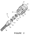
- Figure 2 is an exploded view of the fault disconnector illustrated in Figure 1;
- Figure 3 is an enlarged view of a second embodiment of a surge arrester according to the present invention;
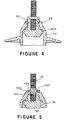
- Figure 4 illustrates a third embodiment of a surge arrester according to the present invention; and,
- Figure 5 illustrates a fourth embodiment of a surge arrester according to the present invention.
-
- As shown in Figure 1, a
surge arrester 10 includes afirst terminal end 12 and asecond terminal end 14. Thefirst terminal end 12 includes afirst connector 16 which is used to electrically connect thesurge arrester 10 to a first electrical line. Thesecond terminal end 14 includes asecond connector 18 which is used to electrically connect thesurge arrester 10 to a second electrical line. The first electrical line may be, for example, an electrically conducting lead which connects thefirst connector 16 to a high voltage line of an electrical power distribution system, and the second electrical line may be an electrically conducting lead which connects thesecond connector 18 to ground. Alternatively, however, the first electrical line may be, for example, an electrically conducting lead which connects thefirst connector 16 to ground, and the second electrical line may be an electrically conducting lead which connects thesecond connector 18 to a high voltage line of an electrical power distribution system. - The
first connector 16 is threaded into afirst end cap 20, and thesecond connector 18 is electrically connected to asecond end cap 22 in a manner to be described below. The first andsecond end caps surge arresting element 24 is in electrical contact with thefirst end cap 20, a secondsurge arresting element 26 is in electrical contact with the firstsurge arresting element 24, a thirdsurge arresting element 28 is in electrical contact with the secondsurge arresting element 26, and a fourthsurge arresting element 30 is in electrical contact with both the thirdsurge arresting element 28 and thesecond end cap 22. Accordingly, a series circuit is formed between the first andsecond end caps second connectors - An arrester housing 32 houses the first and
second end caps surge arresting elements arrester housing 32 may be an insulating polymeric or porcelain housing having a plurality of polymeric orporcelain water sheds 34. Amounting bracket 36 is provided in order to mount and support the surge arrester 10 to a utility pole or other apparatus of an electric power distribution system. - As shown in Figures 1 and 2, the
second end cap 22 has afirst end 40 which is in electrical contact with the fourthsurge arresting element 30. Thesecond end cap 22 also has asecond end 42 which comprises awall 44 forming arecess 46. Afault disconnector 47 includes acartridge 48 which is contained within anend 50 of thesecond connector 18. Thefault disconnector 47 also includes a first electricallyconductive washer 52 abutting theend 50 of thesecond connector 18, a second electricallyconductive washer 54 abutting aninternal wall 58 of thesecond end cap 22, and aresistor 56 sandwiched between the first and second electricallyconductive washers plastic cup 59 contains the first and second electricallyconductive washers resistor 56 when thefault disconnector 47 is assembled as shown in Figure 1. Thus, theplastic cup 59 insulates theresistor 56 and the first and second electricallyconductive washers wall 44 of thesecond end cap 22 forcing fault current to flow from thesecond end cap 22 through the second electricallyconductive washer 54, through theresistor 56, through the first electricallyconductive washer 52, and through thesecond connector 18. - The
wall 44 of thesecond end cap 22 has acircumferential groove 60 therearound. During assembly of thesurge arrester 10, thesurge arresting elements second end caps surge arresting elements second end caps surge arresting elements second end caps arrester housing 32 is applied to the wrapped stack of thesurge arresting elements second end caps arrester housing 32 may be molded directly on the wrapped stack of thesurge arresting elements second end caps - The
arrester housing 32 is mounted to themounting bracket 36 by inserting thewall 44 through an opening 62 in themounting bracket 36 as shown in Figure 1. Themounting bracket 36 may have a first recess 64 and a second recess 66 which are concentric with respect to one another. The first recess 64 is formed by a generallycylindrical wall 68 of themounting bracket 36. The generallycylindrical wall 68 may have an internal taper. As thesecond end cap 22 is pushed through the opening 62 in themounting bracket 36, aflange 70 of thesecond end cap 22 enters the second recess 66 of themounting bracket 36, and the taper of the generallycylindrical wall 68 causes an end portion 72 of thearrester housing 32 to be squeezed between the generallycylindrical wall 68 and theflange 70 of thesecond end cap 22. As a result of this squeezing action, the end portion 72 acts as a gasket or seal at thesecond terminal end 14 in order to isolate the interior of thearrester housing 32 from the external environment. When thearrester housing 32 is fully pressed into the opening 62 of themounting bracket 36 so that thecircumferential groove 60 is accessible, asnap ring 73 is snapped into thecircumferential groove 60 in thewall 44 of thesecond end cap 22 to thereby clamp thesurge arrester 10 to themounting bracket 36 with enough force to maintain the seal by the end portion 72 between the generallycylindrical wall 68 and theflange 70 of thesecond end cap 22. - A
subassembly 74 is formed by inserting thesecond connector 18, with thecartridge 48 inserted in theend 50, through theplastic cup 59 until theplastic cup 59 abuts aflange 76 at theend 50 of thesecond connector 18, and by inserting the first electricallyconductive washer 52 into theplastic cup 59 until the first electricallyconductive washer 52 abuts theflange 76 at theend 50 of thesecond connector 18. Theresistor 56 is inserted into theplastic cup 59 until theresistor 56 abuts the first electricallyconductive washer 52, and the second electricallyconductive washer 54 is placed on top of theresistor 56. Thesubassembly 74 is then inserted into therecess 46 of thesecond end cap 22 until the second electricallyconductive washer 54 abuts theinternal wall 58, leaving aspace 78 as shown in Figure 1. Thespace 78 is filled with an epoxy potting material in order to hold thesubassembly 74 in electrical contact with thesecond end cap 22. - Accordingly, the
recess 46 in thesecond end cap 22 forms a disconnector housing for thefault disconnector 47 so as to eliminate the need for a separate housing for thefault disconnector 47. - Instead of using the
snap ring 73 in thecircumferential groove 60 of thesecond end cap 22 to clamp the first and second end caps 20 and 22, thesurge arresting elements arrester housing 32 to the mountingbracket 36, thesecond end cap 22 may be threaded into the mountingbracket 36. To this end, thesecond end cap 22 may be externally threaded at aregion 80 as shown in Figure 3. - As shown in Figure 1, the
arrester housing 32 is formed over thefirst end cap 20 so as to provide a seal in cooperation with aflange 90 of thefirst connector 16. This seal at the firstterminal end 12 isolates the interior of thearrester housing 32 from the external environment. Alternatively, thearrester housing 32 may be configured with an integral O-ring 92 as shown in Figure 4. The integral O-ring 92 fits within anannular groove 94 about afirst end cap 20A in order to provide a seal at the firstterminal end 12 that isolates the interior of thearrester housing 32 from the external environment. - Instead of configuring an integral O-ring according to the integral O-
ring 92 shown in Figure 4, an integral O-ring 100 may be provided as shown in Figure 5. The integral O-ring 100 is integrally formed in thearrester housing 32 at its top and defines anopening 102 through which thefirst connector 16 extends so that it may be threaded into thefirst end cap 20. The integral O-ring 100 fits within anannular recess 104 formed in aflange 106 of thefirst connector 16. As thefirst connector 16 is threaded into thefirst end cap 20, the integral O-ring 100 is tightly squeezed into theannular recess 104 and cooperates with theflange 106 in order to provide a seal at the firstterminal end 12 that isolates the interior of thearrester housing 32 from the external environment. - Certain modifications of the present invention have been discussed above. Other modifications will occur to those practicing in the art of the present invention. For example, the
first connector 16 and thefirst end cap 20 are shown as being separate elements. Instead, thefirst connector 16 and thefirst end cap 20 may be formed as a single, integrated, electrically conductive element. - Also, four
surge arresting elements - Moreover, as described above, the
surge arrester 10 is assembled in the following order. First, thesurge arresting elements surge arresting elements arrester housing 32 is applied to the wrapped stack of thesurge arresting elements bracket 36. Third, thesubassembly 74 is applied to thesecond end cap 22. Instead, thesurge arrester 10 may be assembled in any desired order. For example, thesurge arresting elements surge arresting elements arrester housing 32 may be applied to the stackedsurge arresting elements subassembly 74 may be applied to thesecond end cap 22. Third, the resulting arrangement may be then secured to the mountingbracket 36. - Additionally, the first and second end caps 20 and 22 may be referred to as surge arresting elements insofar as they facilitate the surge arresting function described above.
- Furthermore, the
plastic cup 59 may be formed of any type of electrical insulating material other than plastic. - Also, an electrically conductive spring, such as a spring washer, may be inserted between the second electrically
conductive washer 54 and theinternal wall 58. - Accordingly, the description of the present invention is to be construed as illustrative only and is for the purpose of teaching those skilled in the art the best mode of carrying out the invention. The details may be varied substantially without departing from the invention as defined in the appended claims.
Claims (17)
- A surge arrester (10) having a surge arresting element (24, 26, 28, and/or 30), a first end cap (20) arranged to electrically connect the surge arresting element (24, 26,28, and/or 30) to a first electrical line, a second end cap (22) electrically connected to the surge arresting element (24, 26, 28, and/or 30), and a fault disconnector (47) arranged to electrically connect the second end cap (22) to a second electrical line, wherein the surge arresting element (24, 26, 28, and/or 30) is arranged to conduct in the presence of a surge, wherein the second end cap (22) has first and second ends (40 and 42), wherein the fault disconnector (47) is arranged to disconnect the surge arresting element from the second electrical line in the event of a fault, the surge arrester BEING CHARACTERIZED in that;
the first end (40) of the second end cap (22) is in direct electrical engagement with the surge arresting element (24, 26, 28, and/or 30), the second end (42) of the second end cap (22) is recessed (46) to form a disconnector housing, the second end cap (22) is substantially conductive throughout, and the fault disconnector (47) is housed within the disconnector housing formed by the second end cap (22). - The surge arrester of claim 1 wherein the first electrical line is a power line.
- The surge arrester of claim 1 or claim 2 wherein the first and second end caps (20 and 22) are in electrical contact with the surge arresting element.
- The surge arrester of any preceding claim wherein the surge arresting element (24, 26, 28, and/or 30) is a metal oxide varistor.
- The surge arrester of any preceding claim further comprising a mounting bracket (36) arranged to support the surge arresting element (24, 26, 28, and/or 30), the first and second end caps (20 and 22), and the fault disconnector (47).
- The surge arrester of any preceding claim further comprising a fastener (73) arranged to fasten the surge arresting element (24, 26, 28, and/or 30), the first and second end caps (20 and 22), and the fault disconnector (47) to the mounting bracket (36) so that the mounting bracket (36) is clamped between the second end cap (22) and the fastener (73) .
- The surge arrester of claim 1 wherein, the surge arresting element (24, 26, 28, and/or 30) comprises a plurality of surge arresting elements (24, 26, 28, and 30).
- The surge arrester of any preceding claim wherein the second electrical line is substantially at ground.
- The surge arrester of any preceding claim wherein the first and second end caps (20 and 22) are in electrical contact with the surge arresting element (24, 26, 28, and/or 30).
- The surge arrester of any preceding claim wherein the arrester housing (32) has a protrusion in the form of an O-ring (92), and wherein the protrusion is arranged to form a seal with respect to the first end cap (20).
- The surge arrester of any preceding claim wherein the first end cap (20) has first and second ends, wherein the second end is in electrical engagement with the surge arresting element (24, 26, 28, and/or 30), and wherein the arrester housing (32) forms a seal over the first end of the first end cap (20) .
- The surge arrester of any preceding claim further comprising an arrester housing (32) arranged to house the surge arresting element (24, 26, 28, and/or 30) and the first and second end caps (20 and 22).
- The surge arrester of claim 8 further comprising a mounting bracket (36) arranged to support the surge arresting element (24, 26, 28, and/or 30), the first and second end caps (20 and 22), the arrester housing (32), and the fault disconnector (47).
- The surge arrester of claim 13 wherein the arrester housing (32) is arranged to form a seal with respect to the mounting bracket (36) and the second end cap (22).
- The surge arrester of claim 13 or claim 14 further comprising a fastener (73) arranged to fasten the surge arresting element (24, 26, 28, and/or 30), the first and second end caps (20 and 22), the arrester housing (32), and the fault disconnector (47) to the mounting bracket (36) so that mounting bracket (36) is clamped between the second end cap (22) and the fastener (73).
- The surge arrester of claim 15 wherein the arrester housing (32) is arranged to be wedged between the mounting bracket (36) and the second end cap (22) when the mounting bracket (36) is clamped between the second end cap (22) and the fastener (73) so as to form a seal.
- The surge arrester of claim 15 or claim 16 wherein the mounting bracket (36) has first and second recesses (64 and 66), wherein the first recess (64) is formed by a wall (68) of the mounting bracket (36), wherein the wall (68) is tapered, wherein the second recess (66) is arranged to receive a flange (70) of the second end cap (22), and wherein the arrester housing (32) is arranged to be wedged between the tapered wall (68) of the mounting bracket (36) and the flange (70) of the second end cap (22) when the mounting bracket (36) is clamped between the second end cap (22) and the fastener (73) so as to form a seal.
Applications Claiming Priority (5)
| Application Number | Priority Date | Filing Date | Title |
|---|---|---|---|
| US90732797A | 1997-08-06 | 1997-08-06 | |
| US907327 | 1997-08-06 | ||
| US08/954,987 US5923518A (en) | 1997-08-06 | 1997-10-21 | Surge arrester having disconnector housed by end cap |
| US954987 | 1997-10-21 | ||
| PCT/US1998/011099 WO1999008353A1 (en) | 1997-08-06 | 1998-06-01 | Surge arrester having disconnector housed by end cap |
Publications (2)
| Publication Number | Publication Date |
|---|---|
| EP1002350A1 EP1002350A1 (en) | 2000-05-24 |
| EP1002350B1 true EP1002350B1 (en) | 2002-12-04 |
Family
ID=27129488
Family Applications (1)
| Application Number | Title | Priority Date | Filing Date |
|---|---|---|---|
| EP98923871A Expired - Lifetime EP1002350B1 (en) | 1997-08-06 | 1998-06-01 | Surge arrester having disconnector housed by end cap |
Country Status (9)
| Country | Link |
|---|---|
| EP (1) | EP1002350B1 (en) |
| JP (1) | JP2001512895A (en) |
| CN (1) | CN1282287C (en) |
| BR (1) | BR9811131A (en) |
| CA (1) | CA2296421A1 (en) |
| DE (1) | DE69809926D1 (en) |
| ID (1) | ID23967A (en) |
| TW (1) | TW466813B (en) |
| WO (1) | WO1999008353A1 (en) |
Families Citing this family (12)
| Publication number | Priority date | Publication date | Assignee | Title |
|---|---|---|---|---|
| JP2001023807A (en) * | 1999-07-09 | 2001-01-26 | Toshiba Corp | Arrester and method of manufacturing the same |
| US6519129B1 (en) | 1999-11-02 | 2003-02-11 | Cooper Industries, Inc. | Surge arrester module with bonded component stack |
| US8323232B2 (en) | 2000-08-24 | 2012-12-04 | Cardiac Science Corporation | Instrument with a two-part plunger for subcutaneous implantation |
| US7736330B2 (en) | 2000-08-24 | 2010-06-15 | Bardy Gust H | Subcutaneous implantation instrument with dissecting tool and method of construction |
| EP1283575B2 (en) * | 2001-08-10 | 2011-03-23 | ABB Schweiz AG | Electric component protected against arc interference |
| US7436283B2 (en) | 2003-11-20 | 2008-10-14 | Cooper Technologies Company | Mechanical reinforcement structure for fuses |
| US8117739B2 (en) | 2004-01-23 | 2012-02-21 | Cooper Technologies Company | Manufacturing process for surge arrester module using pre-impregnated composite |
| US7075406B2 (en) | 2004-03-16 | 2006-07-11 | Cooper Technologies Company | Station class surge arrester |
| US7633737B2 (en) | 2004-04-29 | 2009-12-15 | Cooper Technologies Company | Liquid immersed surge arrester |
| CN114613563A (en) * | 2020-12-08 | 2022-06-10 | 西安西电避雷器有限责任公司 | A lightning arrester and a processing method of a lightning arrester |
| US11894166B2 (en) | 2022-01-05 | 2024-02-06 | Richards Mfg. Co., A New Jersey Limited Partnership | Manufacturing process for surge arrestor module using compaction bladder system |
| US12444522B2 (en) | 2022-01-05 | 2025-10-14 | Richards Mfg. Co. Sales, Llc | Manufacturing process for surge arrestor module using compaction bladder system |
Family Cites Families (4)
| Publication number | Priority date | Publication date | Assignee | Title |
|---|---|---|---|---|
| US4404614A (en) * | 1981-05-15 | 1983-09-13 | Electric Power Research Institute, Inc. | Surge arrester having a non-fragmenting outer housing |
| US4663692A (en) * | 1985-06-27 | 1987-05-05 | Westinghouse Electric Corp. | Electrical surge arrester and disconnector |
| US4734823A (en) * | 1985-11-01 | 1988-03-29 | Joslyn Corporation | Fault current interrupter and explosive disconnector for surge arrester |
| EP0655814A1 (en) * | 1993-11-29 | 1995-05-31 | Joslyn Manufacturing Company | Surge arrester with insulative support bracket |
-
1998
- 1998-06-01 EP EP98923871A patent/EP1002350B1/en not_active Expired - Lifetime
- 1998-06-01 BR BR9811131-0A patent/BR9811131A/en not_active Application Discontinuation
- 1998-06-01 CN CN 98807809 patent/CN1282287C/en not_active Expired - Fee Related
- 1998-06-01 DE DE69809926T patent/DE69809926D1/en not_active Expired - Lifetime
- 1998-06-01 ID IDW20000203A patent/ID23967A/en unknown
- 1998-06-01 CA CA002296421A patent/CA2296421A1/en not_active Abandoned
- 1998-06-01 WO PCT/US1998/011099 patent/WO1999008353A1/en not_active Ceased
- 1998-06-01 JP JP2000506702A patent/JP2001512895A/en active Pending
- 1998-06-04 TW TW87108870A patent/TW466813B/en not_active IP Right Cessation
Also Published As
| Publication number | Publication date |
|---|---|
| BR9811131A (en) | 2000-07-18 |
| JP2001512895A (en) | 2001-08-28 |
| CN1265780A (en) | 2000-09-06 |
| ID23967A (en) | 2000-06-14 |
| DE69809926D1 (en) | 2003-01-16 |
| EP1002350A1 (en) | 2000-05-24 |
| TW466813B (en) | 2001-12-01 |
| CN1282287C (en) | 2006-10-25 |
| WO1999008353A1 (en) | 1999-02-18 |
| CA2296421A1 (en) | 1999-02-18 |
Similar Documents
| Publication | Publication Date | Title |
|---|---|---|
| US5923518A (en) | Surge arrester having disconnector housed by end cap | |
| US5237482A (en) | High voltage surge arrester with failed surge arrester signaling device | |
| US20100118463A1 (en) | Surge arrester with mounting bracket | |
| US5088001A (en) | Surge arrester with rigid insulating housing | |
| US6392861B1 (en) | Surge arrester having disconnector housed by mounting bracket and end cap | |
| US5930102A (en) | Surge arrester having single surge arresting block | |
| MX2008006753A (en) | Insulated cable termination assembly and method of fabrication. | |
| US5434550A (en) | Arrester disconnector | |
| CA2296421A1 (en) | Surge arrester having disconnector housed by end cap | |
| US9824800B2 (en) | Multi-terminal surge arrester | |
| US6876289B2 (en) | Arrester disconnector assembly having a capacitor | |
| US4447848A (en) | Telephone surge protector and housings therefor | |
| US6828895B1 (en) | Arrester disconnector assembly having a capacitor and a resistor | |
| EP0655814A1 (en) | Surge arrester with insulative support bracket | |
| US12191058B2 (en) | Surge arresters and related assemblies and methods | |
| MXPA00001293A (en) | Surge arrester having disconnector housed by end cap | |
| KR100622573B1 (en) | Lightning arrester disconnector | |
| KR100817513B1 (en) | Disconnector | |
| US5307231A (en) | Weatherproof station protection modules | |
| KR200389394Y1 (en) | A disconnector for the surge arrester | |
| EP0107762A1 (en) | Failsafe overvoltage protector | |
| MXPA00003421A (en) | Surge arrester having single surge arresting block |
Legal Events
| Date | Code | Title | Description |
|---|---|---|---|
| PUAI | Public reference made under article 153(3) epc to a published international application that has entered the european phase |
Free format text: ORIGINAL CODE: 0009012 |
|
| 17P | Request for examination filed |
Effective date: 20000224 |
|
| AK | Designated contracting states |
Kind code of ref document: A1 Designated state(s): CH DE ES FR GB GR IE IT LI SE |
|
| 17Q | First examination report despatched |
Effective date: 20010523 |
|
| GRAG | Despatch of communication of intention to grant |
Free format text: ORIGINAL CODE: EPIDOS AGRA |
|
| GRAG | Despatch of communication of intention to grant |
Free format text: ORIGINAL CODE: EPIDOS AGRA |
|
| GRAH | Despatch of communication of intention to grant a patent |
Free format text: ORIGINAL CODE: EPIDOS IGRA |
|
| GRAH | Despatch of communication of intention to grant a patent |
Free format text: ORIGINAL CODE: EPIDOS IGRA |
|
| GRAA | (expected) grant |
Free format text: ORIGINAL CODE: 0009210 |
|
| AK | Designated contracting states |
Kind code of ref document: B1 Designated state(s): CH DE ES FR GB GR IE IT LI SE |
|
| PG25 | Lapsed in a contracting state [announced via postgrant information from national office to epo] |
Ref country code: LI Free format text: LAPSE BECAUSE OF FAILURE TO SUBMIT A TRANSLATION OF THE DESCRIPTION OR TO PAY THE FEE WITHIN THE PRESCRIBED TIME-LIMIT Effective date: 20021204 Ref country code: IT Free format text: LAPSE BECAUSE OF FAILURE TO SUBMIT A TRANSLATION OF THE DESCRIPTION OR TO PAY THE FEE WITHIN THE PRE;WARNING: LAPSES OF ITALIAN PATENTS WITH EFFECTIVE DATE BEFORE 2007 MAY HAVE OCCURRED AT ANY TIME BEFORE 2007. THE CORRECT EFFECTIVE DATE MAY BE DIFFERENT FROM THE ONE RECORDED.SCRIBED TIME-LIMIT Effective date: 20021204 Ref country code: GR Free format text: LAPSE BECAUSE OF FAILURE TO SUBMIT A TRANSLATION OF THE DESCRIPTION OR TO PAY THE FEE WITHIN THE PRESCRIBED TIME-LIMIT Effective date: 20021204 Ref country code: FR Free format text: LAPSE BECAUSE OF FAILURE TO SUBMIT A TRANSLATION OF THE DESCRIPTION OR TO PAY THE FEE WITHIN THE PRESCRIBED TIME-LIMIT Effective date: 20021204 Ref country code: CH Free format text: LAPSE BECAUSE OF FAILURE TO SUBMIT A TRANSLATION OF THE DESCRIPTION OR TO PAY THE FEE WITHIN THE PRESCRIBED TIME-LIMIT Effective date: 20021204 |
|
| REG | Reference to a national code |
Ref country code: GB Ref legal event code: FG4D |
|
| REG | Reference to a national code |
Ref country code: CH Ref legal event code: EP |
|
| REG | Reference to a national code |
Ref country code: IE Ref legal event code: FG4D |
|
| REF | Corresponds to: |
Ref document number: 69809926 Country of ref document: DE Date of ref document: 20030116 |
|
| PG25 | Lapsed in a contracting state [announced via postgrant information from national office to epo] |
Ref country code: SE Free format text: LAPSE BECAUSE OF FAILURE TO SUBMIT A TRANSLATION OF THE DESCRIPTION OR TO PAY THE FEE WITHIN THE PRESCRIBED TIME-LIMIT Effective date: 20030304 |
|
| PG25 | Lapsed in a contracting state [announced via postgrant information from national office to epo] |
Ref country code: DE Free format text: LAPSE BECAUSE OF FAILURE TO SUBMIT A TRANSLATION OF THE DESCRIPTION OR TO PAY THE FEE WITHIN THE PRESCRIBED TIME-LIMIT Effective date: 20030305 |
|
| PG25 | Lapsed in a contracting state [announced via postgrant information from national office to epo] |
Ref country code: IE Free format text: LAPSE BECAUSE OF NON-PAYMENT OF DUE FEES Effective date: 20030602 |
|
| REG | Reference to a national code |
Ref country code: CH Ref legal event code: PL |
|
| PG25 | Lapsed in a contracting state [announced via postgrant information from national office to epo] |
Ref country code: ES Free format text: LAPSE BECAUSE OF FAILURE TO SUBMIT A TRANSLATION OF THE DESCRIPTION OR TO PAY THE FEE WITHIN THE PRESCRIBED TIME-LIMIT Effective date: 20030627 |
|
| PLBE | No opposition filed within time limit |
Free format text: ORIGINAL CODE: 0009261 |
|
| STAA | Information on the status of an ep patent application or granted ep patent |
Free format text: STATUS: NO OPPOSITION FILED WITHIN TIME LIMIT |
|
| EN | Fr: translation not filed | ||
| 26N | No opposition filed |
Effective date: 20030905 |
|
| REG | Reference to a national code |
Ref country code: IE Ref legal event code: MM4A |
|
| PGFP | Annual fee paid to national office [announced via postgrant information from national office to epo] |
Ref country code: GB Payment date: 20060531 Year of fee payment: 9 |
|
| GBPC | Gb: european patent ceased through non-payment of renewal fee |
Effective date: 20070601 |
|
| PG25 | Lapsed in a contracting state [announced via postgrant information from national office to epo] |
Ref country code: GB Free format text: LAPSE BECAUSE OF NON-PAYMENT OF DUE FEES Effective date: 20070601 |