EP1001238B1 - Stack type evaporator - Google Patents
Stack type evaporator Download PDFInfo
- Publication number
- EP1001238B1 EP1001238B1 EP99122256A EP99122256A EP1001238B1 EP 1001238 B1 EP1001238 B1 EP 1001238B1 EP 99122256 A EP99122256 A EP 99122256A EP 99122256 A EP99122256 A EP 99122256A EP 1001238 B1 EP1001238 B1 EP 1001238B1
- Authority
- EP
- European Patent Office
- Prior art keywords
- heat exchanging
- passages
- evaporator
- passage
- inlet
- Prior art date
- Legal status (The legal status is an assumption and is not a legal conclusion. Google has not performed a legal analysis and makes no representation as to the accuracy of the status listed.)
- Expired - Lifetime
Links
Images


Classifications
-
- F—MECHANICAL ENGINEERING; LIGHTING; HEATING; WEAPONS; BLASTING
- F28—HEAT EXCHANGE IN GENERAL
- F28D—HEAT-EXCHANGE APPARATUS, NOT PROVIDED FOR IN ANOTHER SUBCLASS, IN WHICH THE HEAT-EXCHANGE MEDIA DO NOT COME INTO DIRECT CONTACT
- F28D1/00—Heat-exchange apparatus having stationary conduit assemblies for one heat-exchange medium only, the media being in contact with different sides of the conduit wall, in which the other heat-exchange medium is a large body of fluid, e.g. domestic or motor car radiators
- F28D1/02—Heat-exchange apparatus having stationary conduit assemblies for one heat-exchange medium only, the media being in contact with different sides of the conduit wall, in which the other heat-exchange medium is a large body of fluid, e.g. domestic or motor car radiators with heat-exchange conduits immersed in the body of fluid
- F28D1/03—Heat-exchange apparatus having stationary conduit assemblies for one heat-exchange medium only, the media being in contact with different sides of the conduit wall, in which the other heat-exchange medium is a large body of fluid, e.g. domestic or motor car radiators with heat-exchange conduits immersed in the body of fluid with plate-like or laminated conduits
- F28D1/0308—Heat-exchange apparatus having stationary conduit assemblies for one heat-exchange medium only, the media being in contact with different sides of the conduit wall, in which the other heat-exchange medium is a large body of fluid, e.g. domestic or motor car radiators with heat-exchange conduits immersed in the body of fluid with plate-like or laminated conduits the conduits being formed by paired plates touching each other
- F28D1/0325—Heat-exchange apparatus having stationary conduit assemblies for one heat-exchange medium only, the media being in contact with different sides of the conduit wall, in which the other heat-exchange medium is a large body of fluid, e.g. domestic or motor car radiators with heat-exchange conduits immersed in the body of fluid with plate-like or laminated conduits the conduits being formed by paired plates touching each other the plates having lateral openings therein for circulation of the heat-exchange medium from one conduit to another
- F28D1/0333—Heat-exchange apparatus having stationary conduit assemblies for one heat-exchange medium only, the media being in contact with different sides of the conduit wall, in which the other heat-exchange medium is a large body of fluid, e.g. domestic or motor car radiators with heat-exchange conduits immersed in the body of fluid with plate-like or laminated conduits the conduits being formed by paired plates touching each other the plates having lateral openings therein for circulation of the heat-exchange medium from one conduit to another the plates having integrated connecting members
- F28D1/0341—Heat-exchange apparatus having stationary conduit assemblies for one heat-exchange medium only, the media being in contact with different sides of the conduit wall, in which the other heat-exchange medium is a large body of fluid, e.g. domestic or motor car radiators with heat-exchange conduits immersed in the body of fluid with plate-like or laminated conduits the conduits being formed by paired plates touching each other the plates having lateral openings therein for circulation of the heat-exchange medium from one conduit to another the plates having integrated connecting members with U-flow or serpentine-flow inside the conduits
-
- F—MECHANICAL ENGINEERING; LIGHTING; HEATING; WEAPONS; BLASTING
- F25—REFRIGERATION OR COOLING; COMBINED HEATING AND REFRIGERATION SYSTEMS; HEAT PUMP SYSTEMS; MANUFACTURE OR STORAGE OF ICE; LIQUEFACTION SOLIDIFICATION OF GASES
- F25B—REFRIGERATION MACHINES, PLANTS OR SYSTEMS; COMBINED HEATING AND REFRIGERATION SYSTEMS; HEAT PUMP SYSTEMS
- F25B39/00—Evaporators; Condensers
- F25B39/02—Evaporators
- F25B39/022—Evaporators with plate-like or laminated elements
Definitions
- the present invention relates in general to heat exchangers for use in automotive air conditioners, and more particularly to evaporators of a stack type.
- FIGs. 24 to 26 which is described in for example Japanese Patent First Provisional Publication 62-798 and Japanese Patent 2,737,286.
- the first conventional evaporator 1 comprises a core unit 5.
- Refrigerant inlet and outlet pipes 3 and 4 are fluidly connected to the core unit 5, which are held by a coupler 2.
- a liquid-gaseous refrigerant is led into the core unit 5 through the inlet pipe 3 and evaporates to cool the core unit 5.
- air flowing through the core unit 5 is cooled.
- Gaseous refrigerant produced as a result of the evaporation is led into the outlet pipe 4 and into a compressor (not shown).
- the evaporator 1 is of a so-called "stack type" which comprises a plurality of elongate flat tubes or heat exchanging elements which are stacked, each including two mutually coupled elongate shell plates.
- Japanese Patent 2737286 shows an alternate arrangement of two areas for the refrigerant, one being a lower temperature area mainly occupied by a liquid refrigerant and the other being a higher temperature area mainly occupied by a gaseous refrigerant. With this alternate arrangement, the evaporator can exhibit a desired temperature distribution thereon.
- the evaporator 1 and a heater core 9 are arranged perpendicular to a dash panel 8 by which an engine room 6 and a passenger room 7 are partitioned, and air for conditioning the passenger room is forced to flow in the direction of the arrow "a", that is, in a direction parallel with the dash panel 8.
- a duct is provided in the passenger room 7 to assure such air flow. That is, the evaporator 1 and the heater core 9 are installed in the duct.
- the coupler 2 is exposed to the engine room 6 through an opening 10 formed in the dash panel 8, so that the evaporator 1 is fluidly connected through pipes to a compressor (not shown) and a condenser (not shown) which are arranged in the engine room 6.
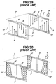
- Figs. 27 to 30 The other conventional stack type evaporator 1' is shown in Figs. 27 to 30, which is described in for example Japanese Patent First Provisional Publication 62-798 and Japanese Utility Model First Provisional Publication 7-12778.
- the second conventional evaporator 1' comprises a core unit 3'.
- the core unit 3' comprises a plurality of elongate flat tubes 10' (or heat exchanging elements) which are stacked, each including two mutually coupled elongate shell plates.
- Each elongate flat tube 10' has two mutually independent flow passages 2' and 2' defined therein.
- a plurality of heat radiation fins 11' are alternatively disposed in the stacked elongate flat tubes 10'.
- the two passages 2' and 2' defined in each flat tube 10' have upper and lower tank spaces.
- a side tank portion 7' by which the two tank portions 4' and 4' are connected.
- a liquid-gaseous refrigerant is led through an inlet pipe 8' and the inlet tank portion 5' (see Fig. 28) into the core unit 3'.
- the refrigerant flows in the passages 2' and 2' of the core unit 3' while evaporating to cool the core unit 3'.
- the refrigerant flows also in the side tank portion 7'.
- air flowing through the core unit 3' in the direction of the arrow " ⁇ " (see Figs. 28 to 30) is cooled.
- Gaseous refrigerant produced as a result of the evaporation is led to an outlet pipe 9' and to a compressor (not shown).
- the side tank portion 7' does not contribute anything to the air cooling because the portion 7' is positioned away from the air passing path. This brings about unsatisfied performance of the air conditioner.
- the refrigerant flowing in the lower tank portions 4' and 4' of the core unit 3' is forced to feed a smaller amount of refrigerant to upstream positioned flow passages 2' and 2' and a larger amount of refrigerant to downstream positioned flow passages 2' and 2'.
- the amount of the refrigerant in each area of the flow passages 2' and 2' is indicated by the up-pointed arrows in the drawing. That is, the refrigerant flow rate in the core unit 3' is smaller in the inside portion than the outside portion.
- the core unit 3' fails to have a uniformed temperature distribution therethroughout.
- the outside portions of the core unit 3' indicated by grids are forced to show a low temperature as compared with the inside portions thereof. This means that the air passing through the core unit 3' fails to have a uniformed temperature distribution, which tends to make passengers in the passenger room uncomfortable.
- a stack type evaporator comprising the features according to the generic part of claim 1 is known from document US 4,809,518.
- this evaporator there can occur the problem that, in case of a limited space, a positioning of inlet and outlet pipes is difficult.
- a stack type evaporator which comprises the features according to claim 1.
- a motor vehicle comprising the features according to claim 11.
- FIG. 1 to 13 of the drawings there is shown a stack type evaporator 100.
- the evaporator 100 has a rectangular core unit 105 which comprises a first group of heat exchanging elements 111, a second group of heat exchanging elements 112, and a plurality of hear radiation fins 113 interposed between every adjacent two of the heat exchanging elements 111 and 112.
- first group of heat exchanging elements 111 will be referred to first heat exchanging element 111
- second group of heat exchanging elements 112 will be referred to second heat exchanging element 112, hereinafter.
- an inlet pipe connector 114 and an outlet pipe connector 115 At an upper middle portion of the core unit 105, there are provided an inlet pipe connector 114 and an outlet pipe connector 115.
- the evaporator 100 upon arrangement of the evaporator 100 in an associated automotive air conditioner, the evaporator 100 is so oriented as having the pipe connectors 114 and 115 directed against an air flow.
- the inlet pipe connector 114 is connected to an inlet pipe 103 through which a liquid-gaseous refrigerant is led into the core unit 105
- the outlet pipe connector 115 is connected to an outlet pipe 104 through which a gaseous refrigerant is discharged from the core unit 105.
- the inlet pipe connector 114 (or outlet pipe connector 115) has a circular opening with which an end of the inlet pipe 103 (or outlet pipe 104) is engaged and brazed.
- the pipe 103 or 104 may have a connector 114 or 115 integrally connected thereto.
- a sealing piece 116 is used for shutting the open end of the integrated connector 114 or 115.
- the connector 114 or 115 may be integrated with a recessed metal plate 117 which is a part of an associated heat exchanging element 111 or 112.
- each of the first group of heat exchanging elements 111 comprises two identical recessed metal plates 117, only one being shown in the drawings.
- each of the second group of heat exchanging elements 112 comprises two identical recessed metal plates 118, only one being shown in the drawings.
- the two identical metal plates 117 and 117 are coupled in a so-called face-to-face connecting manner to define therebetween a hermetically sealed flat flow passage. More specifically, as is understood from Figs. 4A and 5B, the first heat exchanging element 111 is constructed to have therein two parallel straight flow passages 120 and 121, while, as is understood from Figs. 4B and 6B, the second heat exchanging element 112 is constructed to have therein a U-shaped flow passage 122, for the reason which will become apparent as the description proceeds.
- one of the first and second recessed metal plates 117 and 118 may have such a structure as shown in Fig. 9A, 9B or 9C. If the structures as shown in Figs. 9B and 9C are used, reduction in number of parts is achieved because of the integrated formation of the connector 114 or 115.
- Each of the recessed metal plates 117 and 118 is a clad metal which includes an aluminum alloy core plate of higher melting point having both surfaces laminated with brazing aluminum alloy plates of lower melting point. Usually, adding silicon (Si) to the aluminum alloy lowers the melting point of the alloy.
- a plurality of coupled metal plates 117 and 117 for the first group of heat exchanging elements 111, a plurality of coupled metal plates 118 and 118 for the second group of heat exchanging elements 112, a plurality of heat radiation fins 113, inlet and outlet pipe connectors 114 and 115 and a pair of side plates 119 are temporarily assembled in a holder (not shown) in such an arrangement as shown in Fig. 1, and then the temporarily assembled unit is put into a brazing furnace (not shown) for a certain time to braze the parts. With this, the parts 117, 118, 113, 103, 104, 114, 115 and 119 are brazed to one another to constitute a fixed unit of the evaporator 100.
- a right half of the stack type evaporator 100 (see Fig. 1) comprises a plurality of the first heat exchanging elements 111 (viz., first group of heat exchanging elements 111) and associated heat radiation fins 113, and a left half of the evaporator 100 comprises a plurality of the second heat exchanging elements 112 (viz., second group of heat exchanging elements 112) and associated heat radiation fins 113.
- each first heat exchanging element 111 has therein two parallel straight flow passages 120 and 121, and as is shown in Fig. 4B, each second heat exchanging element 112 has therein a U-shaped flow passage 122.
- each metal plate 117 for the first heat exchanging element 111 has at an upper end two (viz., first and second) circular openings 123 and 124, and at a lower end two (viz., third and fourth) circular openings 125 and 126, each opening 123, 124, 125 or 126 being defined in a depressed part of the upper or lower end of the plate 117. Furthermore, each metal plate 117 has two parallel shallow grooves 127 and 128 which extend between the openings 123 and 125 and between the openings 124 and 126, respectively. It is to be noted that the shallow groove 127 constitutes the straight flow passage 120 of the first heat exchanging element 111 (see Fig. 4A), and the other shallow groove 128 constitutes the other straight flow passage 121 of the first heat exchanging element 111.
- the two metal plates 117 and 117 are coupled in a face-to-face contacting manner to constitute the first heat exchanging element 111.
- the element 111 becomes to have at its upper end two (viz., first and second) tank spaces 129 and 130, and at its lower end two (third and fourth) tank spaces 131 and 132, the first tank space 129 being defined between the opening 123 of the metal plate 117 and the corresponding opening (124) of the partner metal plate 117, the second tank space 130 being defined between the opening 124 of the metal plate 117 and the corresponding opening (123) of the partner metal plate 117, the third tank space 131 being defined between the opening 125 of the metal plate 117 and the corresponding opening (126) of the partner metal plate 117 and the fourth tank space 132 being defined between the opening 126 of the metal plate 117 and the corresponding opening (125) of the partner metal plate 117.
- the two parallel straight flow passages 120 and 121 there are defined in the element 111 (see Fig. 4A) the two parallel straight flow passages 120 and 121.
- the passage 120 extends between the first tank space 129 and the third tank space 131, and the other passage 121 extends between the second tank space 130 and the fourth tank space 132.
- bottom surfaces of the two parallel shallow grooves 127 and 128 of each metal plate 117 are formed with a plurality of studs 133.
- the studs 133 of one metal plate 117 abut against the studs 133 of the partner's metal plate 117 respectively.
- These abutting studs 133 become brazed when heated in the brazing furnace. Due to provision of such studs 133, the coupling between the paired metal plates 117 and 117 is assured and the refrigerant flow in the two flow passages 120 and 121 is suitably diffused.
- each metal plate 118 for the second heat exchanging element 112 has an upper end two (fifth and sixth) circular openings 134 and 135, and at a lower end two (viz., seventh and eighth) circular openings 136 and 137, each opening 134, 135, 136 or 137 being defined in a depressed part of the upper and lower end of the plate 118.
- each metal plate 118 has a U-shaped shallow groove 138 which comprises two parallel shallow groove parts (no numerals) each having one end connected to the seventh or eighth circular opening 136 or 137 and a short shallow groove part (no numeral) connecting the other ends of the two parallel shallow groove parts.
- U-shaped shallow groove 138 constitutes the U-shaped flow passage 121 of the second heat exchanging element 112 (see Fig. 4B).
- the two metal plates 118 and 118 are coupled in a face-to-face contacting manner to constitute the second heat exchanging element 112.
- the element 112 becomes to have at its upper end two (viz., fifth and sixth) tank spaces 139 and 140, and at its lower end two (viz., seventh and eighth) tank spaces 141 and 142, the fifth tank space 139 being defined between the opening 134 of the metal plate 118 and the corresponding opening (135) of the partner metal plate 118, the sixth tank space 140 being defined between the opening 135 of the metal plate 118 and the corresponding opening (134) of the partner metal plate 118, the seventh tank space 141 being defined between the opening 136 of the metal plate 118 and the corresponding opening (137) of the partner metal plate 118 and the eighth tank space 142 being defined between the opening 137 of the metal plate 118 and the corresponding opening (136) of the partner metal plate 118.
- the U-shaped flow passage 122 extends between the seventh and eighth tank spaces 141 and 142. It is to be noted that the passage 122 is isolated from the fifth and sixth tank spaces 139 and 140, as is seen from the drawing (Fig. 4B).
- a bottom surface of the U-shaped shallow groove 138 of each metal plate 118 is formed with a plurality of studs 133.
- the studs 133 of one metal plate 118 abut against the studs 133 of the partner's metal plate 118 respectively.
- the abutting studs 133 become brazed when heated in the brazing furnace.
- the fifth and sixth tank spaces 139 and 140 may be removed. However, in this case, it becomes necessary to provide between the upper ends of any adjacent two of the second heat exchanging elements 112 and 112 a distance keeping element.
- the first tank spaces 129 of the first heat exchanging elements 111 are aligned and connected to one another to constitute an inlet tank portion 143.
- the inlet tank portion 143 is connected through the inlet pipe connector 114 to the inlet pipe 103. It is to be noted that the rightmost one of the first metal plates 117 as viewed in Figs. 1 and 3 has no opening corresponding to the opening 123 (see Fig. 5B).
- the second tank spaces 130 of the first heat exchanging elements 111 are aligned and connected to one another to constitute an outlet tank portion 145.
- the outlet tank portion 145 is connected through the outlet pipe connector 115 to the outlet pipe 104. It is to be noted that the rightmost one of the first metal plates 117 as viewed in Figs. 1 and 3 has no opening corresponding to the opening 124 (see Fig. 5B).
- the third tank spaces 131 of the first heat exchanging elements 111 and the seventh tank spaces 141 of the second heat exchanging elements 112 are aligned and connected to one another to constitute a refrigerant flow upstream tank portion 146.
- the rightmost one of the second metal plates 118 as viewed in Fig. 7 has no opening corresponding to the opening 136 and the leftmost one of the first metal plates 117 has no opening corresponding to the opening 125.
- the fourth tank spaces 132 of the first heat exchanging elements 111 and the eighth tank spaces 142 of the second heat exchanging elements 112 are aligned and connected to one another to constitute a refrigerant flow downstream tank portion 147.
- the rightmost one of the second metal plates 118 as viewed in Fig. 7 has no opening corresponding to the opening 137 and the leftmost one of the first metal plates 117 has no opening corresponding to the opening 126.
- a liquid-gaseous refrigerant which has been discharged from an expansion valve (not shown), is led into the inlet tank portion 143 through the inlet pipe connector 114 and the inlet pipe 103.
- the refrigerant in the inlet tank portion 143 then flows down into the straight flow passages 120 of the first group heat exchanging elements 111 which are arranged at the left-half (as viewed in Fig. 7) and air downstream side of the core unit 105 of the evaporator 100.
- the refrigerant in the straight flow passages 120 then flows into a left half part (as viewed in Figs. 7 and 10) of the refrigerant flow upstream tank portion 146.
- the refrigerant makes a heat exchanging with the air which flows through the core unit 105 in the direction of the arrow " ⁇ " of the drawings.
- the air is cooled by a certain degree.
- the refrigerant can flow evenly in both the air flow downstream part and the air flow upstream part of the core unit 105. That is, the flow passages 120 through which the lowest temperature refrigerant flows are arranged just behind the flow passages 121 through which the highest temperature refrigerant flows, and the intermediate temperature refrigerant flows in the U-shaped flow passages 122 which extend between the air flow upstream and downstream parts of the core unit 105.
- the core unit 105 of the evaporator 100 can have an even temperature distribution therethroughout. This provides the air passing through the core unit 105 with a uniformed temperature distribution, which makes the passengers comfortable. Furthermore, such even temperature distribution of the core unit 105 brings about an effective heat exchanging between the refrigerant flowing in the core unit 105 and the air passing through the core unit 105.
- the evaporator 100 is so oriented as having the pipe connectors 114 and 115 directed against the air flow.
- the connection of the inlet and outlet pipes 103 and 104 to the coupler 2 held by the dash panel 8 is readily and simply made, which brings about a low cost production of the automotive air conditioner as well as a smoothed air flow passing through the evaporator 100.
- the evaporator 100 since the evaporator 100 has no structure corresponding the side tank portion 7' (see Fig. 28) possessed by the conventional evaporator 1', lowering in heat exchanging performance caused by such side tank portion 7' does not occur.
- FIG. 14 and 15 there is shown a modification 100A of the evaporator 100.
- the inlet pipe 103 is connected to a left end portion (as viewed in Fig. 14) of the core unit 105, and the outlet pipe 104 is connected to a right end portion (as viewed in Fig. 14) of the core unit 105.
- the inlet tank portion 143 extends throughout the width of the core unit 105, as shown. That is, in this modification 100A, the first tank spaces 129 (see Fig. 7) of the first heat exchanging elements 111 and the fifth tank spaces 139 of the second heat exchanging elements 112 are connected to constitute the inlet tank portion 143.
- the outlet tank portion 145 is arranged at a right half air flow upstream side of the core unit 105, as shown in the drawing.
- FIG. 16 to 21 there is shown an evaporator 100B according to the invention.
- refrigerant inlet and outlet pipes 152 and 153 are connected through a connector 154 (see Fig. 18) to an upper portion of one side end of the core unit 105.
- the inlet tank portion 143 and the outlet tank portion 145 extend throughout the width of the core unit 105. That is, the first tank spaces 129 of the first heat exchanging elements 111 and the fifth tank spaces 139 of the second heat exchanging elements 112 are connected to constitute the inlet tank portion 143, and the second tank spaces 130 of the first heat exchanging elements 111 and the sixth tank spaces 140 of the second heat exchanging elements 112 are connected to constitute the outlet tank portion 145.
- the connector 154 is secured to the outermost one of the second heat exchanging elements 112. More specifically, as is seen from Fig. 19, the connector 154 is secured to the outside one of the paired recessed metal plates 118 of the element 112.
- the outside metal plate 118 is formed with two openings 155 and 156 which are respectively communicated with the fifth tank spaces 139 and the sixth tank spaces 140 of the core unit 105.
- the inlet and outlet pipes 152 and 153 held by the connector 154 are respectively mated with the openings 155 and 156 of the outside metal plate 118.
- the inlet pipe 152 extends to an expansion valve and the outlet pipe 153 extends to a compressor.
- a relatively low temperature zone of the flow passages 120 and a relatively high temperature zone of the flow passages 121 are overlapped to each other with respect to the air flowing direction.
- the core unit 105 of the evaporator 100B can have an even temperature distribution therethroughout.
- the inlet and outlet pipes 152 and 153 are aligned with the inlet and outlet tank portions 143 and 145 of the core unit 105, the inflow of the refrigerant into the inlet tank portion 143 and the outflow of the refrigerant from the outlet tank portion 145 are smoothly carried out and thus the refrigerant flow resistance of the evaporator 100B can be reduced.
- FIG. 22 there is shown a further modification 100C of the evaporator 100.
- a side plate 119' provided with an extra side tank 158 is employed for reducing the dynamic pressure possessed by the refrigerant just fed to the core unit 105.
- a passage 159 defined in the extra side tank 158 has one end connected to the inlet tank portion 143 and the other end connected to the refrigerant inlet pipe 152.
- the dynamic pressure possessed by the refrigerant just fed to the core unit 105 is effectively reduced and thus undesired drift of the refrigerant flow in the flow passages 120 of the first heat exchanging elements 111 is suppressed or at least minimized.
- the refrigerant outlet pipe 153 should be aligned with the outlet tank portion 145 because the gaseous refrigerant flowing in the outlet tank portion 145 is easily affected in flow resistance by the complication in structure of the flow passage as compared with the liquid-gaseous refrigerant fed into the core unit 105.
- FIG. 23 there is shown a further modification 100D of the evaporator 100.
- refrigerant inlet and outlet pipes 152 and 153 are connected to laterally opposed ends of the core unit 105. Furthermore, in this modification 100D, the outlet tank portion 145 is provided at only one half part of the core unit 105. That is, the second tank spaces 130 of the first heat exchanging elements 111 located at a right half (as viewed in Fig. 23) of the core unit 105 are connected to constitute the outlet tank portion 145.
Abstract
Description
- The present invention relates in general to heat exchangers for use in automotive air conditioners, and more particularly to evaporators of a stack type.
- In order to clarify the tasks of the present invention, two conventional
stack type evaporators 1 and 1' for automotive air conditioners will be described with reference to Figs. 24 to 26 and Figs. 27 to 30. - One of them is shown in Figs. 24 to 26, which is described in for example Japanese Patent First Provisional Publication 62-798 and Japanese Patent 2,737,286.
- As is seen from Figs. 24 and 25, the first
conventional evaporator 1 comprises acore unit 5. Refrigerant inlet andoutlet pipes core unit 5, which are held by acoupler 2. Under operation, a liquid-gaseous refrigerant is led into thecore unit 5 through theinlet pipe 3 and evaporates to cool thecore unit 5. With this, air flowing through thecore unit 5 is cooled. Gaseous refrigerant produced as a result of the evaporation is led into theoutlet pipe 4 and into a compressor (not shown). Theevaporator 1 is of a so-called "stack type" which comprises a plurality of elongate flat tubes or heat exchanging elements which are stacked, each including two mutually coupled elongate shell plates. Japanese Patent 2737286 shows an alternate arrangement of two areas for the refrigerant, one being a lower temperature area mainly occupied by a liquid refrigerant and the other being a higher temperature area mainly occupied by a gaseous refrigerant. With this alternate arrangement, the evaporator can exhibit a desired temperature distribution thereon. - As is seen from Fig. 25, in assembly of the air conditioner, the
evaporator 1 and aheater core 9 are arranged perpendicular to adash panel 8 by which anengine room 6 and apassenger room 7 are partitioned, and air for conditioning the passenger room is forced to flow in the direction of the arrow "a", that is, in a direction parallel with thedash panel 8. Although not shown in the drawing, a duct is provided in thepassenger room 7 to assure such air flow. That is, theevaporator 1 and theheater core 9 are installed in the duct. Thecoupler 2 is exposed to theengine room 6 through anopening 10 formed in thedash panel 8, so that theevaporator 1 is fluidly connected through pipes to a compressor (not shown) and a condenser (not shown) which are arranged in theengine room 6. - Nowadays, for improving air flow in the
passenger room 7, there has been proposed an arrangement wherein, as is seen from Fig. 26, theevaporator 1 and theheater core 9 are arranged in parallel with thedash panel 8, and the air for conditioning theroom 7 is forced to flow in the direction of the arrow "b". However, in this case, it becomes necessary to use much longer and complicated pipes as the inlet andoutlet pipes longer pipes - The other conventional stack type evaporator 1' is shown in Figs. 27 to 30, which is described in for example Japanese Patent First Provisional Publication 62-798 and Japanese Utility Model First Provisional Publication 7-12778.
- As is seen from the drawings, the second conventional evaporator 1' comprises a core unit 3'. The core unit 3' comprises a plurality of elongate flat tubes 10' (or heat exchanging elements) which are stacked, each including two mutually coupled elongate shell plates. Each elongate flat tube 10' has two mutually independent flow passages 2' and 2' defined therein. A plurality of heat radiation fins 11' are alternatively disposed in the stacked elongate flat tubes 10'. The two passages 2' and 2' defined in each flat tube 10' have upper and lower tank spaces. By connecting or communicating adjacent flat tubes 10' at the respective upper and lower tank spaces, there are formed a plurality of tank portions 4', 5' and 6'. As is seen from Figs. 28 to 30, at one end of the core unit 3', there is provided a side tank portion 7' by which the two tank portions 4' and 4' are connected. Under operation, a liquid-gaseous refrigerant is led through an inlet pipe 8' and the inlet tank portion 5' (see Fig. 28) into the core unit 3'. The refrigerant flows in the passages 2' and 2' of the core unit 3' while evaporating to cool the core unit 3'. During this, the refrigerant flows also in the side tank portion 7'. Thus, air flowing through the core unit 3' in the direction of the arrow "α" (see Figs. 28 to 30) is cooled. Gaseous refrigerant produced as a result of the evaporation is led to an outlet pipe 9' and to a compressor (not shown).
- However, the above-mentioned other conventional stack type evaporator 1' has the following drawbacks due to its inherent construction.
- First, actually, the side tank portion 7' does not contribute anything to the air cooling because the portion 7' is positioned away from the air passing path. This brings about unsatisfied performance of the air conditioner.
- Second, as is seen from Fig. 29, under operation of the evaporator 1', due to the nature of the gravity, the liquid-gaseous refrigerant flowing in the upper tank portions 5' and 4' of the core unit 3' is forced to feed a larger amount of refrigerant to upstream positioned flow passages 2' and 2' and a smaller amount of refrigerant to downstream positioned flow passages 2' and 2'. The amount of the refrigerant in each area of the flow passages 2' and 2' is indicated by the down-pointed arrows in the drawing. While, due to inertia of the refrigerant, the refrigerant flowing in the lower tank portions 4' and 4' of the core unit 3' is forced to feed a smaller amount of refrigerant to upstream positioned flow passages 2' and 2' and a larger amount of refrigerant to downstream positioned flow passages 2' and 2'.
The amount of the refrigerant in each area of the flow passages 2' and 2' is indicated by the up-pointed arrows in the drawing. That is, the refrigerant flow rate in the core unit 3' is smaller in the inside portion than the outside portion. Thus, as is seen from Fig. 31, the core unit 3' fails to have a uniformed temperature distribution therethroughout. That is, in the drawing, the outside portions of the core unit 3' indicated by grids are forced to show a low temperature as compared with the inside portions thereof. This means that the air passing through the core unit 3' fails to have a uniformed temperature distribution, which tends to make passengers in the passenger room uncomfortable. - Further, a stack type evaporator comprising the features according to the generic part of
claim 1 is known from document US 4,809,518. However, when using this evaporator there can occur the problem that, in case of a limited space, a positioning of inlet and outlet pipes is difficult. - It is therefore an object of the present invention to provide a stack type evaporator which is free of the above-mentioned drawbacks.
- According to a first aspect of the present invention, there is provided a stack type evaporator which comprises the features according to
claim 1. - According to a second aspect of the present invention, there is provided a motor vehicle comprising the features according to
claim 11. - Other objects and advantages of the present invention will become apparent from the following description when taken in conjunction with the accompanying drawings, in which:
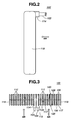
- Fig. 1 is front view of a stack type evaporator;
- Fig. 2 is a side view of the evaporator;
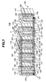
- Fig. 3 is a plan view of the evaporator;
- Fig. 4A is a schematic sectional view of one heat exchanging element employed in the evaporator, which is taken from the direction "IV" of Fig. 1;
- Fig. 4B is a view similar to Fig. 4A, but showing another exchanging element employed in the evaporator ;
- Fig. 5A is a sectional view of the heat exchanging element of Fig. 4A, which is taken from the direction "VA" of Fig. 5B;
- Fig. 5B is a sectional view of the heat exchanging element of Fig. 4A, which is taken from the direction "VB" of Fig. 5A;
- Fig. 6A is a sectional view of the heat exchanging element of Fig. 4B, which is taken from the direction "VIA" of Fig. 6B;
- Fig. 6B is a sectional view of the heat exchanging element of Fig. 4B, which is taken from the direction "VIB" of Fig. 6A;
- Fig. 7 is a schematically illustrated perspective view of the evaporator, showing the path of refrigerant;
- Figs. 8A and 8B are perspective view of two connector constructions employable in the invention;
- Figs. 9A, 9B and 9C are perspective views of upper portions of three recessed metal plates each being an essential part of a heat exchanging element, the upper portions having connector structures;
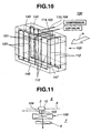
- Fig. 10 is a schematically illustrated perspective view of the evaporator , showing the path of refrigerant in the evaporator;
- Fig. 11 is a schematic plan view of a part of a motor vehicle where the evaporator associated with an air conditioner is operatively arranged;
- Fig. 12 is a schematic perspective view of the evaporator, showing the flow condition of refrigerant in the evaporator;
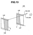
- Fig. 13 is a schematic view of the evaporator showing a temperature distribution possessed by the evaporator;
- Fig. 14 is a view similar to Fig. 10, but showing a modification of the evaporator;
- Fig. 15 is a schematic plan view of a part of a motor vehicle where the first modification of the evaporator associated with an air conditioner is operatively arranged;
- Fig. 16 is a schematic view of an evaporator of the present invention, showing the path of refrigerant in the evaporator;
- Fig. 17 is a schematic perspective view of the evaporator of the invention;
- Fig. 18 is an exploded perspective view of one heat exchanging element and its associated connector structure, which are employed in the evaporator of Fig. 17;
- Fig. 19 is a sectional view of an assembled unit including the heat exchanging element and the associated connector structure of Fig. 18;
- Fig. 20 is a view similar to Fig. 14, but showing the flow condition of refrigerant in the evaporator of the invention;
- Fig. 21 is a view similar to Fig. 15, but showing a temperature distribution possessed by the evaporator of the invention;
- Fig. 22 is a view similar to Fig. 18, but showing a further modification of an evaporator ;
- Fig. 23 is a view similar to Fig. 16, but showing a further modification of an evaporator ;
- Fig. 24 is a perspective view of a conventional evaporator;
- Fig. 25 is a plan view of a part of a motor vehicle where the first conventional evaporator associated with an air conditioner is operatively arranged;
- Fig. 26 is a view similar to Fig. 25, but showing a drawback which is possessed by the conventional evaporator when the same is arranged in a different way;
- Fig. 27 is a perspective view of a further conventional evaporator;
- Fig. 28 is a schematic perspective view of the further conventional evaporator, showing the path of refrigerant in the evaporator;
- Fig. 29 is a schematic perspective view of the further conventional evaporator, showing flow condition of refrigerant in the evaporator;
- Fig. 30 is a schematic view of the further conventional evaporator, showing a temperature distribution possessed by the evaporator.
-
- In the following, the present invention will be described in detail with reference to the accompanying drawings. For ease of understanding, directional terms, such as, right, left, upper, tower and the like are used. However, these directional terms are to be understood with respect to the drawings in which the objective structures or parts are illustrated.
- Referring to Figs. 1 to 13 of the drawings, particularly Figs. 1, 2, 3, 7 and 10, there is shown a
stack type evaporator 100. - As is seen from Figs. 1, 2 and 3, the
evaporator 100 has arectangular core unit 105 which comprises a first group ofheat exchanging elements 111, a second group ofheat exchanging elements 112, and a plurality of hearradiation fins 113 interposed between every adjacent two of theheat exchanging elements heat exchanging elements 111 will be referred to firstheat exchanging element 111, and each of the second group ofheat exchanging elements 112 will be referred to secondheat exchanging element 112, hereinafter. - As is seen from Figs. 1, 2 and 3, at an upper middle portion of the
core unit 105, there are provided aninlet pipe connector 114 and anoutlet pipe connector 115. As is understood from Fig. 2, upon arrangement of theevaporator 100 in an associated automotive air conditioner, theevaporator 100 is so oriented as having thepipe connectors inlet pipe connector 114 is connected to aninlet pipe 103 through which a liquid-gaseous refrigerant is led into thecore unit 105, and theoutlet pipe connector 115 is connected to anoutlet pipe 104 through which a gaseous refrigerant is discharged from thecore unit 105. - As is seen from Fig. 8A, the inlet pipe connector 114 (or outlet pipe connector 115) has a circular opening with which an end of the inlet pipe 103 (or outlet pipe 104) is engaged and brazed. However, if desired, as is seen from Fig. 8B, the
pipe connector sealing piece 116 is used for shutting the open end of theintegrated connector - Furthermore, as is seen from Figs. 9B and 9C, the
connector metal plate 117 which is a part of an associatedheat exchanging element - That is, as is shown in Fig. 5A and 5B, each of the first group of
heat exchanging elements 111 comprises two identical recessedmetal plates 117, only one being shown in the drawings. As is shown in Figs. 6A and 6B, each of the second group ofheat exchanging elements 112 comprises two identical recessedmetal plates 118, only one being shown in the drawings. - The two
identical metal plates 117 and 117 (or, 118 and 118) are coupled in a so-called face-to-face connecting manner to define therebetween a hermetically sealed flat flow passage. More specifically, as is understood from Figs. 4A and 5B, the firstheat exchanging element 111 is constructed to have therein two parallelstraight flow passages heat exchanging element 112 is constructed to have therein aU-shaped flow passage 122, for the reason which will become apparent as the description proceeds. - As will be described hereinafter, one of the first and second recessed
metal plates connector - Each of the recessed
metal plates - For producing the
evaporator 100, a plurality of coupledmetal plates heat exchanging elements 111, a plurality of coupledmetal plates heat exchanging elements 112, a plurality ofheat radiation fins 113, inlet andoutlet pipe connectors side plates 119 are temporarily assembled in a holder (not shown) in such an arrangement as shown in Fig. 1, and then the temporarily assembled unit is put into a brazing furnace (not shown) for a certain time to braze the parts. With this, theparts evaporator 100. - As has been mentioned hereinabove, a right half of the stack type evaporator 100 (see Fig. 1) comprises a plurality of the first heat exchanging elements 111 (viz., first group of heat exchanging elements 111) and associated
heat radiation fins 113, and a left half of theevaporator 100 comprises a plurality of the second heat exchanging elements 112 (viz., second group of heat exchanging elements 112) and associatedheat radiation fins 113. - As is shown in Fig. 4A, each first
heat exchanging element 111 has therein two parallelstraight flow passages heat exchanging element 112 has therein aU-shaped flow passage 122. - As is seen in Fig. 5B, each
metal plate 117 for the firstheat exchanging element 111 has at an upper end two (viz., first and second)circular openings circular openings opening plate 117. Furthermore, eachmetal plate 117 has two parallelshallow grooves openings openings shallow groove 127 constitutes thestraight flow passage 120 of the first heat exchanging element 111 (see Fig. 4A), and the othershallow groove 128 constitutes the otherstraight flow passage 121 of the firstheat exchanging element 111. - As has been mentioned hereinabove, the two
metal plates heat exchanging element 111. With this coupling, as is seen from Fig. 4A, theelement 111 becomes to have at its upper end two (viz., first and second)tank spaces tank spaces first tank space 129 being defined between the opening 123 of themetal plate 117 and the corresponding opening (124) of thepartner metal plate 117, thesecond tank space 130 being defined between the opening 124 of themetal plate 117 and the corresponding opening (123) of thepartner metal plate 117, thethird tank space 131 being defined between the opening 125 of themetal plate 117 and the corresponding opening (126) of thepartner metal plate 117 and thefourth tank space 132 being defined between the opening 126 of themetal plate 117 and the corresponding opening (125) of thepartner metal plate 117. - Furthermore, with the coupling between the two
metal plates heat exchanging element 111, there are defined in the element 111 (see Fig. 4A) the two parallelstraight flow passages passage 120 extends between thefirst tank space 129 and thethird tank space 131, and theother passage 121 extends between thesecond tank space 130 and thefourth tank space 132. - As is seen from Fig. 5B, bottom surfaces of the two parallel
shallow grooves metal plate 117 are formed with a plurality ofstuds 133. Upon coupling between the pairedmetal plates studs 133 of onemetal plate 117 abut against thestuds 133 of the partner'smetal plate 117 respectively. These abuttingstuds 133 become brazed when heated in the brazing furnace. Due to provision ofsuch studs 133, the coupling between the pairedmetal plates flow passages - As is seen in Fig. 6, each
metal plate 118 for the secondheat exchanging element 112 has an upper end two (fifth and sixth)circular openings circular openings opening plate 118. Furthermore, eachmetal plate 118 has a U-shapedshallow groove 138 which comprises two parallel shallow groove parts (no numerals) each having one end connected to the seventh or eighthcircular opening shallow groove 138 constitutes theU-shaped flow passage 121 of the second heat exchanging element 112 (see Fig. 4B). - As has been mentioned hereinabove, the two
metal plates heat exchanging element 112. With this coupling, as is seen from Fig. 4B, theelement 112 becomes to have at its upper end two (viz., fifth and sixth)tank spaces tank spaces fifth tank space 139 being defined between the opening 134 of themetal plate 118 and the corresponding opening (135) of thepartner metal plate 118, thesixth tank space 140 being defined between the opening 135 of themetal plate 118 and the corresponding opening (134) of thepartner metal plate 118, theseventh tank space 141 being defined between the opening 136 of themetal plate 118 and the corresponding opening (137) of thepartner metal plate 118 and theeighth tank space 142 being defined between the opening 137 of themetal plate 118 and the corresponding opening (136) of thepartner metal plate 118. - Furthermore, with the coupling between the two
metal plates heat exchanging element 112, there are defined in the element 112 (see Fig. 4B) theU-shaped flow passage 122. Thispassage 122 extends between the seventh andeighth tank spaces passage 122 is isolated from the fifth andsixth tank spaces - As is seen from Fig. 6B, a bottom surface of the U-shaped
shallow groove 138 of eachmetal plate 118 is formed with a plurality ofstuds 133. Upon coupling between the pairedmetal plates studs 133 of onemetal plate 118 abut against thestuds 133 of the partner'smetal plate 118 respectively. The abuttingstuds 133 become brazed when heated in the brazing furnace. If desired, the fifth andsixth tank spaces heat exchanging elements 112 and 112 a distance keeping element. - As is seen from Figs. 3 and 7, upon assembly of the
evaporator 100, thefirst tank spaces 129 of the firstheat exchanging elements 111 are aligned and connected to one another to constitute aninlet tank portion 143. Theinlet tank portion 143 is connected through theinlet pipe connector 114 to theinlet pipe 103. It is to be noted that the rightmost one of thefirst metal plates 117 as viewed in Figs. 1 and 3 has no opening corresponding to the opening 123 (see Fig. 5B). - Furthermore, as is seen from Figs. 3 and 7, upon assembly of the
evaporator 100, thesecond tank spaces 130 of the firstheat exchanging elements 111 are aligned and connected to one another to constitute anoutlet tank portion 145. Theoutlet tank portion 145 is connected through theoutlet pipe connector 115 to theoutlet pipe 104. It is to be noted that the rightmost one of thefirst metal plates 117 as viewed in Figs. 1 and 3 has no opening corresponding to the opening 124 (see Fig. 5B). - As is seen from Fig. 7, upon assembly, the
third tank spaces 131 of the firstheat exchanging elements 111 and theseventh tank spaces 141 of the secondheat exchanging elements 112 are aligned and connected to one another to constitute a refrigerant flowupstream tank portion 146. It is to be noted that the rightmost one of thesecond metal plates 118 as viewed in Fig. 7 has no opening corresponding to theopening 136 and the leftmost one of thefirst metal plates 117 has no opening corresponding to theopening 125. - Furthermore, as is seen from Fig. 7, upon assembly, the
fourth tank spaces 132 of the firstheat exchanging elements 111 and theeighth tank spaces 142 of the secondheat exchanging elements 112 are aligned and connected to one another to constitute a refrigerant flowdownstream tank portion 147. It is to be noted that the rightmost one of thesecond metal plates 118 as viewed in Fig. 7 has no opening corresponding to theopening 137 and the leftmost one of thefirst metal plates 117 has no opening corresponding to theopening 126. - In the following, operation of the
stack type evaporator 100 will be described with reference to Figs. 7 and 10. - Under operation of the associated air conditioner, a liquid-gaseous refrigerant, which has been discharged from an expansion valve (not shown), is led into the
inlet tank portion 143 through theinlet pipe connector 114 and theinlet pipe 103. The refrigerant in theinlet tank portion 143 then flows down into thestraight flow passages 120 of the first groupheat exchanging elements 111 which are arranged at the left-half (as viewed in Fig. 7) and air downstream side of thecore unit 105 of theevaporator 100. The refrigerant in thestraight flow passages 120 then flows into a left half part (as viewed in Figs. 7 and 10) of the refrigerant flowupstream tank portion 146. - The refrigerant led into the left-half part of the refrigerant flow
upstream tank portion 146 flows in theportion 146 rightward in the drawing. Then, the refrigerant is led into theU-shaped flow passages 122 of the second groupheat exchanging elements 112 which constitute the right-half part of thecore unit 105 in the drawings. The refrigerant in theU-shaped flow passages 122 then flows into a right half part of the refrigerant flowdownstream tank portion 147. Then, the refrigerant flows leftward (as viewed in Figs. 7 and 10) in thetank portion 147 and then flows upward into thestraight flow passages 121 of the first groups heat exchangingelements 111. The refrigerant then flows into theoutlet tank portion 145 and then flows into a compressor through theoutlet pipe connector 115 and theoutlet pipe 104. - During the above-mentioned flow in the
core unit 105, the refrigerant makes a heat exchanging with the air which flows through thecore unit 105 in the direction of the arrow "α" of the drawings. Thus, the air is cooled by a certain degree. - As is easily understood from Fig. 10, due to the above-mentioned unique arrangement of the refrigerant flow passages, the refrigerant can flow evenly in both the air flow downstream part and the air flow upstream part of the
core unit 105. That is, theflow passages 120 through which the lowest temperature refrigerant flows are arranged just behind theflow passages 121 through which the highest temperature refrigerant flows, and the intermediate temperature refrigerant flows in theU-shaped flow passages 122 which extend between the air flow upstream and downstream parts of thecore unit 105. - Furthermore, as is understood from Figs. 12 and 13, under operation, the inside side section "X" of the air flow downstream left-half part of the
evaporator 100 is permitted to let a larger amount of liquid-gaseous refrigerant flow therethrough, and the outside section "Y" of the air flow upstream left-half part of theevaporator 100 is permitted to let a larger amount of gaseous refrigerant flow therethrough. It is to be noted that these two sections "X" and "Y" are not overlapped with respect to the direction in which the air "α" flows. This means that a relatively low temperature zone of theflow passages 120 and a relatively high temperature zone of theflow passages 121 are overlapped to each other with respect to the air flowing direction. - Thus, the
core unit 105 of theevaporator 100 can have an even temperature distribution therethroughout. This provides the air passing through thecore unit 105 with a uniformed temperature distribution, which makes the passengers comfortable. Furthermore, such even temperature distribution of thecore unit 105 brings about an effective heat exchanging between the refrigerant flowing in thecore unit 105 and the air passing through thecore unit 105. - In each of the right and left half parts (as viewed in Figs. 7 and 10) of the
core unit 105, higher temperature refrigerant flows in the air flow upstream part of thecore unit 105 and lower temperature refrigerant flows in the air flow downstream part of theunit 105. This promotes the uniformed temperature distribution of the air passing through thecore unit 105. - As is described hereinabove, the
evaporator 100 is so oriented as having thepipe connectors evaporator 100 is arranged in parallel with thedash panel 8, the connection of the inlet andoutlet pipes coupler 2 held by thedash panel 8 is readily and simply made, which brings about a low cost production of the automotive air conditioner as well as a smoothed air flow passing through theevaporator 100. - Furthermore, since the
evaporator 100 has no structure corresponding the side tank portion 7' (see Fig. 28) possessed by the conventional evaporator 1', lowering in heat exchanging performance caused by such side tank portion 7' does not occur. - Referring to Figs. 14 and 15, there is shown a
modification 100A of theevaporator 100. - In this
first modification 100A, theinlet pipe 103 is connected to a left end portion (as viewed in Fig. 14) of thecore unit 105, and theoutlet pipe 104 is connected to a right end portion (as viewed in Fig. 14) of thecore unit 105. For this arrangement, theinlet tank portion 143 extends throughout the width of thecore unit 105, as shown. That is, in thismodification 100A, the first tank spaces 129 (see Fig. 7) of the firstheat exchanging elements 111 and thefifth tank spaces 139 of the secondheat exchanging elements 112 are connected to constitute theinlet tank portion 143. Theoutlet tank portion 145 is arranged at a right half air flow upstream side of thecore unit 105, as shown in the drawing. - As is seen from Fig. 15, even when the modified
evaporator 100A is arranged in parallel with thedash panel 8, the connection of the inlet andoutlet pipes coupler 2 is readily and simply made, which brings about a low cost production of the automotive air conditioner and a smoothed air flow passing through theevaporator 100A. - Referring to Figs. 16 to 21, there is shown an evaporator 100B according to the invention.
- As is seen from Figs. 16 and 17, in this
evaporator 100B, refrigerant inlet andoutlet pipes core unit 105. For this arrangement, theinlet tank portion 143 and theoutlet tank portion 145 extend throughout the width of thecore unit 105. That is, thefirst tank spaces 129 of the firstheat exchanging elements 111 and thefifth tank spaces 139 of the secondheat exchanging elements 112 are connected to constitute theinlet tank portion 143, and thesecond tank spaces 130 of the firstheat exchanging elements 111 and thesixth tank spaces 140 of the secondheat exchanging elements 112 are connected to constitute theoutlet tank portion 145. - As is seen from Figs. 18 and 19, the
connector 154 is secured to the outermost one of the secondheat exchanging elements 112. More specifically, as is seen from Fig. 19, theconnector 154 is secured to the outside one of the paired recessedmetal plates 118 of theelement 112. For this connection, theoutside metal plate 118 is formed with twoopenings fifth tank spaces 139 and thesixth tank spaces 140 of thecore unit 105. The inlet andoutlet pipes connector 154 are respectively mated with theopenings outside metal plate 118. Theinlet pipe 152 extends to an expansion valve and theoutlet pipe 153 extends to a compressor. - As is seen from Figs. 20 and 21, also in this
evaporator 100B, under operation, the inside side section "X" of the air flow downstream left-half part of the evaporator 100B is permitted to let a larger amount of liquid-gaseous refrigerant flow therethrough, and the outside section "Y" of the air flow upstream left-half part of the evaporator 100B is permitted to let a larger amount of gaseous refrigerant flow therethrough. Like in the case of the above-mentionedevaporator 100, the two sections "X'' and "Y" are not overlapped with respect to the direction in which the air "α" flows. That is, also in thisevaporator 100B, a relatively low temperature zone of theflow passages 120 and a relatively high temperature zone of theflow passages 121 are overlapped to each other with respect to the air flowing direction. Thus, thecore unit 105 of the evaporator 100B can have an even temperature distribution therethroughout. - Furthermore, since, in this
evaporator 100B (see Fig. 20), the inlet andoutlet pipes outlet tank portions core unit 105, the inflow of the refrigerant into theinlet tank portion 143 and the outflow of the refrigerant from theoutlet tank portion 145 are smoothly carried out and thus the refrigerant flow resistance of the evaporator 100B can be reduced. - Referring to Fig. 22, there is shown a
further modification 100C of theevaporator 100. - Since this
modification 100C is similar in construction to the above-mentionedsecond modification 100B, only parts different from those of thesecond modification 100B will be described. - That is, as is shown in the drawing, a side plate 119' provided with an
extra side tank 158 is employed for reducing the dynamic pressure possessed by the refrigerant just fed to thecore unit 105. As shown, apassage 159 defined in theextra side tank 158 has one end connected to theinlet tank portion 143 and the other end connected to therefrigerant inlet pipe 152. In this case, the dynamic pressure possessed by the refrigerant just fed to thecore unit 105 is effectively reduced and thus undesired drift of the refrigerant flow in theflow passages 120 of the firstheat exchanging elements 111 is suppressed or at least minimized. Even in thismodification 100C, therefrigerant outlet pipe 153 should be aligned with theoutlet tank portion 145 because the gaseous refrigerant flowing in theoutlet tank portion 145 is easily affected in flow resistance by the complication in structure of the flow passage as compared with the liquid-gaseous refrigerant fed into thecore unit 105. - Referring to Fig. 23, there is shown a
further modification 100D of theevaporator 100. - As shown, in this
modification 100D, refrigerant inlet andoutlet pipes core unit 105. Furthermore, in thismodification 100D, theoutlet tank portion 145 is provided at only one half part of thecore unit 105. That is, thesecond tank spaces 130 of the firstheat exchanging elements 111 located at a right half (as viewed in Fig. 23) of thecore unit 105 are connected to constitute theoutlet tank portion 145. - The entire contents of Japanese Patent Application P10-317145 (filed November 9, 1998) and Japanese Patent Application P11-189273 (filed July 2, 1999) are incorporated herein by reference.
- Although the invention has been described above with reference to an embodiment of the invention, the invention is not limited to such an embodiment as described above. Much larger modifications and variations of the invention described above will occur to those skilled in the art, in light of the above teachings.
Claims (11)
- A stack type evaporator comprising:a first mass including first heat exchanging elements (111), each first heat exchanging element (111) having mutually independent first (120) and second (121) passages;a second mass including second heat exchanging elements (112), each second heat exchanging element (112) having a generally U-shaped third passage (122) which has first and second ends (141, 142), said second mass being arranged beside said first mass in such a manner that the first and second heat exchanging elements (111, 112) are aligned on a common axis;an inlet tank passage (143) connecting to upper ends (129) of said first passages (120);an upstream tank passage (146) connecting to lower ends (132) of said first passages (120) and the first ends (141) of said third passages (122);a downstream tank passage (147) connecting to lower ends (132) of said second passages (121) and the second ends (142) of said third passages (122);an outlet tank passage (145) connecting to upper ends (130) of said second passages (120);an inlet pipe (103) connected to said inlet tank passage (143); andan outlet pipe (104) connected to said outlet tank passage (145), characterized in thateach of said second heat exchanging elements (112) has said first and second ends (141, 142) at a lower end portion thereof and has mutually independent first and second openings (139, 140) at an upper end portion thereof,said inlet tank passage (143) connects to the first openings (139) of said second heat exchanging elements (112), andsaid outlet tank passage (145) connects to the second openings (140) of said second heat exchanging elements (112).
- A stack type evaporator as claimed in claim 1, in which said first (120) and second passages (121) of each first heat exchanging element (111) are arranged at downstream and upstream positions with respect to a direction in which air flows through the evaporator, and in which said third passage (122) of each second heat exchanging element (112) comprises a first passage part, a second passage part and a third passage part through which said first and second passage parts are connected, said first and second passage parts being arranged at downstream and upstream positions with respect to the air flowing direction.
- A stack type evaporator as claimed in claim 2, in which said first passages (120) of the first heat exchanging elements (111) and said first passage parts of the second heat exchanging elements (112) are arranged to form a first line, and in which said second passages of the first heat exchanging elements (111) and said second passage parts of the second heat exchanging elements (112) are arranged to form a second line, said second line being positioned more upstream than said first line with respect to the air flowing direction.
- A stack type evaporator as claimed in claim 3, in which said inlet (143) and outlet (145) tank passages extend to the outermost second heat exchanging element (112), and in which said inlet (103) and outlet (104) pipes are respectively connected to the extended inlet and outlet tank passages possessed by said outermost second heat exchanging element (112).
- A stack type evaporator as claimed in claim 4, in which said inlet (103) and outlet (104) pipes are aligned with said inlet (143) and outlet (145) tank passages, respectively.
- A stack type evaporator as claimed in claim 5, in which said outermost second heat exchanging element (112) is provided with a connector (154) through which said inlet (103) and outlet (104) pipes are connected to said inlet (143) and outlet (145) tank passages.
- A stack type evaporator as claimed in claim 6, in which said outermost second heat exchanging element (112) is provided further with an extra side tank (158) for reducing a dynamic pressure possessed by a refrigerant just fed into the inlet tank passage (143) from said inlet pipe (103).
- A stack type evaporator as claimed in claim 7, in which said extra side tank (153) has therein a passage which has one end connected to the inlet tank passage (143) and the other end connected to said inlet pipe (103) held by said connector (154).
- A stack type evaporator as claimed in claim 1, further comprising:first and second side plates (119) respectively attached to outside ones of the heat exchanging elements (111, 112) of said first andsecond masses; anda plurality of heat radiation fins (113) each being interposedbetween adjacent two of the first (111) and second (112) heat exchanging elements.
- A stack type evaporator as claimed in claim 1, in which each of said first (111) and second (112) heat exchanging elements comprises two identical recessed metal plates (117, 118), said two metal plates (117, 118) being coupled in a face-to-face connecting manner to define therebetween a hermetically sealed liquid flow space.
- A motor vehicle having an engine room and a passenger room which are partitioned by a dash panel and comprising:a stack type evaporator according to claim 1;means for placing said evaporator in such a manner that the evaporator is arranged in parallel with said dash panel and that said inlet tank passage and said upstream tank passage are positioned away from said dash panel as compared with said outlet tank passage and said downstream tank passage; andmeans for producing an air flow through said evaporator in a direction from said dash panel toward said evaporator.
Applications Claiming Priority (4)
| Application Number | Priority Date | Filing Date | Title |
|---|---|---|---|
| JP31714598 | 1998-11-09 | ||
| JP10317145A JP2000146362A (en) | 1998-11-09 | 1998-11-09 | Laminated evaporator |
| JP11189273A JP2001021233A (en) | 1999-07-02 | 1999-07-02 | Lamination type evaporator |
| JP18927399 | 1999-07-02 |
Publications (2)
| Publication Number | Publication Date |
|---|---|
| EP1001238A1 EP1001238A1 (en) | 2000-05-17 |
| EP1001238B1 true EP1001238B1 (en) | 2003-06-18 |
Family
ID=26505385
Family Applications (1)
| Application Number | Title | Priority Date | Filing Date |
|---|---|---|---|
| EP99122256A Expired - Lifetime EP1001238B1 (en) | 1998-11-09 | 1999-11-08 | Stack type evaporator |
Country Status (4)
| Country | Link |
|---|---|
| US (1) | US6230787B1 (en) |
| EP (1) | EP1001238B1 (en) |
| AT (1) | ATE243310T1 (en) |
| DE (1) | DE69908888T2 (en) |
Cited By (1)
| Publication number | Priority date | Publication date | Assignee | Title |
|---|---|---|---|---|
| DE10349974A1 (en) * | 2003-10-24 | 2005-05-25 | Behr Gmbh & Co. Kg | Device for exchanging heat, especially for motor vehicle, has coolant that flows in at least one first longitudinal section of device essentially simultaneously through essentially all throughflow devices in this section |
Families Citing this family (11)
| Publication number | Priority date | Publication date | Assignee | Title |
|---|---|---|---|---|
| JP4254015B2 (en) * | 2000-05-15 | 2009-04-15 | 株式会社デンソー | Heat exchanger |
| JP2002107004A (en) * | 2000-09-27 | 2002-04-10 | Calsonic Kansei Corp | Stacked type evaporator |
| AU2002234898B2 (en) * | 2001-02-28 | 2006-05-11 | Showa Denko K.K. | Heat exchanger |
| EP1256772A3 (en) | 2001-05-11 | 2005-02-09 | Behr GmbH & Co. KG | Heat exchanger |
| SE525022C2 (en) * | 2003-04-17 | 2004-11-09 | Ep Technology Ab | Evaporator and heat exchanger with external loop |
| JP4517333B2 (en) | 2003-11-28 | 2010-08-04 | 株式会社ヴァレオサーマルシステムズ | Heat exchanger |
| ES2257209B1 (en) * | 2005-01-13 | 2008-06-16 | Valeo Termico, S.A. | HEAT EXCHANGER OF STACKED PLATES. |
| CN201059823Y (en) * | 2007-06-19 | 2008-05-14 | 上海双桦汽车零部件股份有限公司 | Parallel flow evaporator |
| WO2013058953A1 (en) | 2011-10-19 | 2013-04-25 | Carrier Corporation | Flattened tube finned heat exchanger and fabrication method |
| DE102011090182A1 (en) * | 2011-12-30 | 2013-07-04 | Behr Gmbh & Co. Kg | Kit for heat exchangers, a heat transfer core and a heat exchanger |
| KR101586646B1 (en) * | 2014-03-17 | 2016-01-19 | 주식회사 경동나비엔 | A hot water heating latent heat exchanger and a condensing gas boiler comprising the same |
Family Cites Families (15)
| Publication number | Priority date | Publication date | Assignee | Title |
|---|---|---|---|---|
| US1916549A (en) * | 1932-11-14 | 1933-07-04 | Fred M Young | Heat transferring unit |
| AU550366B1 (en) * | 1985-02-11 | 1986-03-20 | Zexel Corporation | Heat exchanger |
| JPS62798A (en) | 1985-03-28 | 1987-01-06 | Nippon Denso Co Ltd | Heat exchanger |
| JPS6380169A (en) * | 1986-09-24 | 1988-04-11 | カルソニックカンセイ株式会社 | Laminating type evaporator with expansion valve |
| JP2737987B2 (en) * | 1989-03-09 | 1998-04-08 | アイシン精機株式会社 | Stacked evaporator |
| JP2737286B2 (en) | 1989-08-11 | 1998-04-08 | アイシン精機株式会社 | Stacked heat exchanger |
| JPH03186194A (en) * | 1989-12-15 | 1991-08-14 | Nippondenso Co Ltd | Laminar heat exchanger |
| JPH04177094A (en) * | 1990-11-13 | 1992-06-24 | Sanden Corp | Laminated type heat exchanger |
| AU663964B2 (en) * | 1992-08-31 | 1995-10-26 | Mitsubishi Jukogyo Kabushiki Kaisha | Stacked heat exchanger |
| US5353868A (en) * | 1993-04-19 | 1994-10-11 | Abbott Roy W | Integral tube and strip fin heat exchanger circuit |
| JP2605035Y2 (en) | 1993-06-25 | 2000-06-19 | 昭和アルミニウム株式会社 | Stacked heat exchanger |
| GB9324783D0 (en) | 1993-12-02 | 1994-01-19 | Davy Mckee London | Process |
| JPH10265882A (en) * | 1997-03-25 | 1998-10-06 | Mitsubishi Heavy Ind Ltd | Aluminum alloy heat exchanger |
| JPH10281685A (en) * | 1997-03-31 | 1998-10-23 | Zexel Corp | Laminated heat exchanger |
| US6070428A (en) * | 1997-05-30 | 2000-06-06 | Showa Aluminum Corporation | Stack type evaporator |
-
1999
- 1999-11-08 DE DE69908888T patent/DE69908888T2/en not_active Expired - Fee Related
- 1999-11-08 AT AT99122256T patent/ATE243310T1/en not_active IP Right Cessation
- 1999-11-08 EP EP99122256A patent/EP1001238B1/en not_active Expired - Lifetime
- 1999-11-09 US US09/436,491 patent/US6230787B1/en not_active Expired - Fee Related
Cited By (1)
| Publication number | Priority date | Publication date | Assignee | Title |
|---|---|---|---|---|
| DE10349974A1 (en) * | 2003-10-24 | 2005-05-25 | Behr Gmbh & Co. Kg | Device for exchanging heat, especially for motor vehicle, has coolant that flows in at least one first longitudinal section of device essentially simultaneously through essentially all throughflow devices in this section |
Also Published As
| Publication number | Publication date |
|---|---|
| DE69908888T2 (en) | 2003-12-18 |
| EP1001238A1 (en) | 2000-05-17 |
| ATE243310T1 (en) | 2003-07-15 |
| DE69908888D1 (en) | 2003-07-24 |
| US6230787B1 (en) | 2001-05-15 |
Similar Documents
| Publication | Publication Date | Title |
|---|---|---|
| US5042577A (en) | Evaporator | |
| JP4122578B2 (en) | Heat exchanger | |
| US6827139B2 (en) | Heat exchanger for exchanging heat between internal fluid and external fluid and manufacturing method thereof | |
| US5311935A (en) | Corrugated fin type heat exchanger | |
| US6209628B1 (en) | Heat exchanger having several heat exchanging portions | |
| US20060237178A1 (en) | Heat exchanger | |
| US6431264B2 (en) | Heat exchanger with fluid-phase change | |
| EP1001238B1 (en) | Stack type evaporator | |
| KR20030080004A (en) | Heat exchanger | |
| US7293604B2 (en) | Heat exchanger | |
| US7013952B2 (en) | Stack type heat exchanger | |
| EP1195567A1 (en) | Heat exchanger having several heat exchanging portions | |
| US6814135B2 (en) | Stacked-type evaporator | |
| JP3965901B2 (en) | Evaporator | |
| JP3797109B2 (en) | Evaporator | |
| JP2001041678A (en) | Heat exchanger | |
| WO2019207838A1 (en) | Refrigerant distributor, heat exchanger, and air conditioner | |
| JPH10281693A (en) | Duplx type integral heat-exchanger | |
| JPH11192833A (en) | Heat exchanger combination structure and integrated heat exchanger | |
| JP2002048491A (en) | Heat exchanger for cooling | |
| JP2000055573A (en) | Refrigerant evaporator | |
| JPH10281692A (en) | Parallel and integral heat-exchanger | |
| JP3677898B2 (en) | Double heat exchanger | |
| US7650934B2 (en) | Heat exchanger | |
| JPH11337292A (en) | Heat exchanger |
Legal Events
| Date | Code | Title | Description |
|---|---|---|---|
| PUAI | Public reference made under article 153(3) epc to a published international application that has entered the european phase |
Free format text: ORIGINAL CODE: 0009012 |
|
| 17P | Request for examination filed |
Effective date: 19991108 |
|
| AK | Designated contracting states |
Kind code of ref document: A1 Designated state(s): AT BE CH CY DE DK ES FI FR GB GR IE IT LI LU MC NL PT SE |
|
| AX | Request for extension of the european patent |
Free format text: AL;LT;LV;MK;RO;SI |
|
| RAP1 | Party data changed (applicant data changed or rights of an application transferred) |
Owner name: CALSONIC KANSEI CORPORATION |
|
| AKX | Designation fees paid |
Free format text: AT BE CH CY DE DK ES FI FR GB GR IE IT LI LU MC NL PT SE |
|
| 17Q | First examination report despatched |
Effective date: 20010827 |
|
| GRAH | Despatch of communication of intention to grant a patent |
Free format text: ORIGINAL CODE: EPIDOS IGRA |
|
| GRAH | Despatch of communication of intention to grant a patent |
Free format text: ORIGINAL CODE: EPIDOS IGRA |
|
| GRAA | (expected) grant |
Free format text: ORIGINAL CODE: 0009210 |
|
| AK | Designated contracting states |
Designated state(s): AT BE CH CY DE DK ES FI FR GB GR IE IT LI LU MC NL PT SE |
|
| PG25 | Lapsed in a contracting state [announced via postgrant information from national office to epo] |
Ref country code: NL Free format text: LAPSE BECAUSE OF FAILURE TO SUBMIT A TRANSLATION OF THE DESCRIPTION OR TO PAY THE FEE WITHIN THE PRESCRIBED TIME-LIMIT Effective date: 20030618 Ref country code: LI Free format text: LAPSE BECAUSE OF FAILURE TO SUBMIT A TRANSLATION OF THE DESCRIPTION OR TO PAY THE FEE WITHIN THE PRESCRIBED TIME-LIMIT Effective date: 20030618 Ref country code: IT Free format text: LAPSE BECAUSE OF FAILURE TO SUBMIT A TRANSLATION OF THE DESCRIPTION OR TO PAY THE FEE WITHIN THE PRESCRIBED TIME-LIMIT;WARNING: LAPSES OF ITALIAN PATENTS WITH EFFECTIVE DATE BEFORE 2007 MAY HAVE OCCURRED AT ANY TIME BEFORE 2007. THE CORRECT EFFECTIVE DATE MAY BE DIFFERENT FROM THE ONE RECORDED. Effective date: 20030618 Ref country code: FI Free format text: LAPSE BECAUSE OF FAILURE TO SUBMIT A TRANSLATION OF THE DESCRIPTION OR TO PAY THE FEE WITHIN THE PRESCRIBED TIME-LIMIT Effective date: 20030618 Ref country code: CH Free format text: LAPSE BECAUSE OF FAILURE TO SUBMIT A TRANSLATION OF THE DESCRIPTION OR TO PAY THE FEE WITHIN THE PRESCRIBED TIME-LIMIT Effective date: 20030618 Ref country code: BE Free format text: LAPSE BECAUSE OF FAILURE TO SUBMIT A TRANSLATION OF THE DESCRIPTION OR TO PAY THE FEE WITHIN THE PRESCRIBED TIME-LIMIT Effective date: 20030618 Ref country code: AT Free format text: LAPSE BECAUSE OF FAILURE TO SUBMIT A TRANSLATION OF THE DESCRIPTION OR TO PAY THE FEE WITHIN THE PRESCRIBED TIME-LIMIT Effective date: 20030618 |
|
| REG | Reference to a national code |
Ref country code: GB Ref legal event code: FG4D |
|
| REG | Reference to a national code |
Ref country code: CH Ref legal event code: EP |
|
| REG | Reference to a national code |
Ref country code: IE Ref legal event code: FG4D |
|
| REF | Corresponds to: |
Ref document number: 69908888 Country of ref document: DE Date of ref document: 20030724 Kind code of ref document: P |
|
| PG25 | Lapsed in a contracting state [announced via postgrant information from national office to epo] |
Ref country code: SE Free format text: LAPSE BECAUSE OF FAILURE TO SUBMIT A TRANSLATION OF THE DESCRIPTION OR TO PAY THE FEE WITHIN THE PRESCRIBED TIME-LIMIT Effective date: 20030918 Ref country code: PT Free format text: LAPSE BECAUSE OF FAILURE TO SUBMIT A TRANSLATION OF THE DESCRIPTION OR TO PAY THE FEE WITHIN THE PRESCRIBED TIME-LIMIT Effective date: 20030918 Ref country code: GR Free format text: LAPSE BECAUSE OF FAILURE TO SUBMIT A TRANSLATION OF THE DESCRIPTION OR TO PAY THE FEE WITHIN THE PRESCRIBED TIME-LIMIT Effective date: 20030918 Ref country code: DK Free format text: LAPSE BECAUSE OF FAILURE TO SUBMIT A TRANSLATION OF THE DESCRIPTION OR TO PAY THE FEE WITHIN THE PRESCRIBED TIME-LIMIT Effective date: 20030918 |
|
| PG25 | Lapsed in a contracting state [announced via postgrant information from national office to epo] |
Ref country code: ES Free format text: LAPSE BECAUSE OF FAILURE TO SUBMIT A TRANSLATION OF THE DESCRIPTION OR TO PAY THE FEE WITHIN THE PRESCRIBED TIME-LIMIT Effective date: 20030929 |
|
| PG25 | Lapsed in a contracting state [announced via postgrant information from national office to epo] |
Ref country code: LU Free format text: LAPSE BECAUSE OF NON-PAYMENT OF DUE FEES Effective date: 20031108 Ref country code: CY Free format text: LAPSE BECAUSE OF FAILURE TO SUBMIT A TRANSLATION OF THE DESCRIPTION OR TO PAY THE FEE WITHIN THE PRESCRIBED TIME-LIMIT Effective date: 20031108 |
|
| PG25 | Lapsed in a contracting state [announced via postgrant information from national office to epo] |
Ref country code: IE Free format text: LAPSE BECAUSE OF NON-PAYMENT OF DUE FEES Effective date: 20031110 |
|
| PG25 | Lapsed in a contracting state [announced via postgrant information from national office to epo] |
Ref country code: MC Free format text: LAPSE BECAUSE OF NON-PAYMENT OF DUE FEES Effective date: 20031130 |
|
| NLV1 | Nl: lapsed or annulled due to failure to fulfill the requirements of art. 29p and 29m of the patents act | ||
| REG | Reference to a national code |
Ref country code: CH Ref legal event code: PL |
|
| ET | Fr: translation filed | ||
| PLBE | No opposition filed within time limit |
Free format text: ORIGINAL CODE: 0009261 |
|
| STAA | Information on the status of an ep patent application or granted ep patent |
Free format text: STATUS: NO OPPOSITION FILED WITHIN TIME LIMIT |
|
| 26N | No opposition filed |
Effective date: 20040319 |
|
| REG | Reference to a national code |
Ref country code: IE Ref legal event code: MM4A |
|
| PGFP | Annual fee paid to national office [announced via postgrant information from national office to epo] |
Ref country code: DE Payment date: 20081107 Year of fee payment: 10 |
|
| PGFP | Annual fee paid to national office [announced via postgrant information from national office to epo] |
Ref country code: FR Payment date: 20081112 Year of fee payment: 10 |
|
| PGFP | Annual fee paid to national office [announced via postgrant information from national office to epo] |
Ref country code: GB Payment date: 20081105 Year of fee payment: 10 |
|
| REG | Reference to a national code |
Ref country code: GB Ref legal event code: 746 Effective date: 20090924 |
|
| GBPC | Gb: european patent ceased through non-payment of renewal fee |
Effective date: 20091108 |
|
| REG | Reference to a national code |
Ref country code: FR Ref legal event code: ST Effective date: 20100730 |
|
| PG25 | Lapsed in a contracting state [announced via postgrant information from national office to epo] |
Ref country code: FR Free format text: LAPSE BECAUSE OF NON-PAYMENT OF DUE FEES Effective date: 20091130 |
|
| PG25 | Lapsed in a contracting state [announced via postgrant information from national office to epo] |
Ref country code: DE Free format text: LAPSE BECAUSE OF NON-PAYMENT OF DUE FEES Effective date: 20100601 |
|
| PG25 | Lapsed in a contracting state [announced via postgrant information from national office to epo] |
Ref country code: GB Free format text: LAPSE BECAUSE OF NON-PAYMENT OF DUE FEES Effective date: 20091108 |