EP1000787A2 - Vehicle refrigerating cycle apparatus and method for inhibiting cycle corrosion and for facilitating rapid passenger compartment warm-up during low temperature conditions - Google Patents
Vehicle refrigerating cycle apparatus and method for inhibiting cycle corrosion and for facilitating rapid passenger compartment warm-up during low temperature conditions Download PDFInfo
- Publication number
- EP1000787A2 EP1000787A2 EP99120937A EP99120937A EP1000787A2 EP 1000787 A2 EP1000787 A2 EP 1000787A2 EP 99120937 A EP99120937 A EP 99120937A EP 99120937 A EP99120937 A EP 99120937A EP 1000787 A2 EP1000787 A2 EP 1000787A2
- Authority
- EP
- European Patent Office
- Prior art keywords
- compressor
- refrigerant
- suction pressure
- temperature
- circuit
- Prior art date
- Legal status (The legal status is an assumption and is not a legal conclusion. Google has not performed a legal analysis and makes no representation as to the accuracy of the status listed.)
- Granted
Links
Images


Classifications
-
- B—PERFORMING OPERATIONS; TRANSPORTING
- B60—VEHICLES IN GENERAL
- B60H—ARRANGEMENTS OF HEATING, COOLING, VENTILATING OR OTHER AIR-TREATING DEVICES SPECIALLY ADAPTED FOR PASSENGER OR GOODS SPACES OF VEHICLES
- B60H1/00—Heating, cooling or ventilating [HVAC] devices
- B60H1/00642—Control systems or circuits; Control members or indication devices for heating, cooling or ventilating devices
- B60H1/00814—Control systems or circuits characterised by their output, for controlling particular components of the heating, cooling or ventilating installation
- B60H1/00878—Control systems or circuits characterised by their output, for controlling particular components of the heating, cooling or ventilating installation the components being temperature regulating devices
- B60H1/00899—Controlling the flow of liquid in a heat pump system
- B60H1/00914—Controlling the flow of liquid in a heat pump system where the flow direction of the refrigerant does not change and there is a bypass of the condenser
-
- B—PERFORMING OPERATIONS; TRANSPORTING
- B60—VEHICLES IN GENERAL
- B60H—ARRANGEMENTS OF HEATING, COOLING, VENTILATING OR OTHER AIR-TREATING DEVICES SPECIALLY ADAPTED FOR PASSENGER OR GOODS SPACES OF VEHICLES
- B60H1/00—Heating, cooling or ventilating [HVAC] devices
- B60H1/00314—Arrangements permitting a rapid heating of the heating liquid
Definitions
- the present invention relates generally to vehicle air conditioning systems, and particularly to a refrigerating cycle apparatus in which a high temperature/high pressure gas refrigerant discharged from a refrigerant compressor is guided through a pressure reducer and then an internal heat exchanger to heat air flowing through an air conditioner duct.
- a conventional vehicle air conditioning system includes a hot-water warming unit in which engine cooling water is guided to a hot-water heater located in an air conditioning duct to heat air flowing through the duct.
- a hot water warming unit is inefficient during engine startup when both outside air and cooling water temperatures are low.
- Japanese Patent Application Laid-Open No. Hei. 5-223357 describes a vehicle air conditioning apparatus having an auxiliary warming unit adapted to assist the main warming unit by guiding a high temperature/high pressure gas refrigerant discharged from an engine-driven refrigerant compressor to an internal heat exchanger via a pressure reducing unit, so that the heat exchanger heats the air flowing through an air conditioning duct.
- the hot gas heater cycle of the above system is adapted such that heat generated by compression work of the refrigerant compressor is radiated by a vehicle internal heat exchanger.
- the heat is radiated in a manner different from a typical heat pump cycle in which the vehicle internal heat exchanger functions as a refrigerant condenser, and in which a vehicle external heat exchanger functions as a refrigerant evaporator. Therefore, the cycle can operate even when the outside air temperature is very low, such as in the vicinity of -40°C.
- the present invention when the second refrigerant circuit is started at a time of very low outside air temperature, when the physical quantity representative of a detected compressor suction pressure becomes less than a predetermined value, it is possible to prevent air from penetrating into the refrigerant compressor without improving the compressor shaft seal. Air penetration is prevented by controlling the refrigerant compressor to automatically stop the second refrigerant circuit. Further, since it is possible to prevent air from penetrating into the refrigerant compressor, corrosion and abnormally high pressure during first refrigerant circuit startup can be prevented.
- the second refrigerant circuit when the second refrigerant circuit is started during very low outside air temperature conditions, after the suction pressure of the refrigerant compressor or the physical quantity representative of the suction pressure has become less than a predetermined value and the second refrigerant circuit has been automatically stopped, it is possible to assist the main warming unit by restarting the second refrigerant circuit after a predetermined elapsed time so that the vehicle interior can be rapidly warmed during initial startup of the main warming unit.
- a vehicle air conditioner 1 includes an air conditioner control unit ECU 10.
- the air conditioner 1 includes an air conditioning duct 2 forming an air passage 11 for guiding conditioned air into the interior of a vehicle.
- an outside air suction port At an air downstream side of the air conditioning duct 2, an outside air suction port, an inside air suction port and an inside/outside air switching door (not shown) are provided.
- a centrifugal blower 3 and blow ports At an air upstream side, a centrifugal blower 3 and blow ports, such as a defroster blow port, a face blow port and a foot blow port, and a mode switching door (not shown) are provided.
- the centrifugal blower 3 is composed of a scroll casing provided integrally with the air conditioning duct 2, a blower motor 12 controlled by a blower driving circuit (not shown), and a centrifugal fan 13 rotatably driven by the blower motor 12 and having a blowing capacity that may be controlled in a continuous or stepwise manner.
- a hot-water heater 5 of a hot-water warming unit 4 re-heats air that has passed through an evaporator 6.
- the hot-water heater 5 is disposed at a middle location in a cooling water circuit 14, through which a water pump (not shown) driven by a vehicle engine E circulates cooling water. If a hot-water valve 15 disposed in the cooling water circuit 14 is opened, the hot-water heater 5 causes the cooling water, having absorbed the engine exhaust heat of the engine E, to circulate therethrough. As a result, the air is re-heated so that the cooling water becomes a heat source. In other words, it acts as a downstream side, or second, heat exchanger for heating air.
- the hot-water warming unit 4 is composed of the engine E, the hot-water heater 5, the cooling water circuit 14, and the hot-water valve 15.
- the refrigerating cycle unit 20 also includes a first refrigerant circuit 21, a second refrigerant circuit 22, and first and second electromagnetic valves 23, 24 for switching the first and second refrigerant circuits 21, 22.
- the first refrigerant circuit 21 is for circulating a high temperature/high pressure gas refrigerant discharged from a compressor 7 in the following order: first electromagnetic valve 23; condenser 25; receiver 26; expansion valve 27; evaporator 6; accumulator 28; and compressor 7.
- the second refrigerant circuit 22 is for circulating a high temperature/high pressure gas refrigerant discharged from the compressor 7 in the following order: second electromagnetic valve 24; pressure reducing unit; 29; evaporator 6; accumulator 28; and compressor 7.
- the refrigerating cycle unit 20 causes the refrigerant to circulate through the first refrigerant circuit 21. Further, if the first electromagnetic valve 23 is closed and the second electromagnetic valve 24 is opened, the refrigerating cycle unit 20 causes the refrigerant to circulate through the second refrigerant circuit 22.
- the circuit switch includes the first and second electromagnetic valves 23, 24.
- numeral 16 denotes a cooling fan rotatably driven by a drive motor 17 that forcibly blows outside air to the condenser 25.
- the evaporator 6 corresponds to an internal heat exchanger.
- the evaporator causes a low temperature vapor/liquid two-phase refrigerant flowing into the circuit 21 from the expansion valve 27 to evaporate.
- the evaporator 6 functions as a cooling heat exchanger for cooling the air passing through it.
- the evaporator 6 when the refrigerant flows through the second refrigerant circuit 22, the evaporator 6 functions as a first heating heat exchanger for heating the air passing through it by passing a high temperature gas refrigerant flowing into it from the pressure reducing unit 29.
- the expansion valve 27 not only causes the refrigerant to adibiatically expand but also adjusts a circulation amount of the refrigerant in compliance with a refrigerant overheat degree of an evaporator outlet.
- the compressor 7 is preferably an engine-driven piston-type fixed volume compressor which compresses the refrigerant sucked from its suction port and discharges a high temperature/high pressure gas refrigerant from its discharge port.
- An electromagnetic clutch 8 for transmitting or interrupting rotary power of the engine E to or from the compressor 7 is connected to a shaft of the compressor 7. Further, a belt V is rotated both by a pulley 33 of the electromagnetic clutch 8 and a crank pulley of the engine E, thereby facilitating transmission of the engine rotary power to the compressor 7.
- the electromagnetic clutch 8 When the electromagnetic clutch 8 is energized (ON), the engine rotary power is transmitted to the compressor 7 via the belt V and the electromagnetic clutch 8. The refrigerating cycle unit 20 is started, and thus an air cooling action or an air heating action is performed by the evaporator 6. Further, when the electromagnetic clutch 8 is de-energized (OFF), the rotary power of the engine E is not transmitted to the compressor 7, and the air cooling or heating action is stopped.
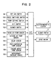
- Respective switch signals from respective switches on an air conditioning operation panel (not shown) provided in the vehicle passenger compartment are input to the air conditioning ECU 10.
- a hot gas switch (S/W) 99 a mode switching switch 100 for switching an air conditioning mode to a cooler mode or a heater mode, a temperature-setting switch 101 for setting a vehicle interior temperature to a desired temperature, an air conditioning switch 102 for starting or stopping the refrigerating cycle unit 20, a blower switch 103 for turning the centrifugal blower 3 ON/OFF, and the like are provided on the air conditioning operation panel.
- a known microcomputer including a CPU, ROM, RAM and the like is provided, and respective sensor signals from respective sensors are input to the microcomputer after being A/D-converted by an input circuit (not shown). It should be appreciated that the air conditioning ECU 10 is programmed so that, when an ignition switch of the engine E is turned on (IG ⁇ ON), control processing is started.
- respective sensor signals from an inside air temperature sensor 104 for detecting a vehicle interior air temperature, an outside air temperature sensor 105 for detecting a vehicle external air temperature, and a solar energy sensor 106 for detecting an amount of solar energy coming into the vehicle interior are input to the ECU 10.
- respective sensor signals from a post-evaporator temperature sensor 107 for detecting the temperature of air just after having passed the evaporator 6, a cooling water temperature sensor 108 for detecting the temperature of cooling water flowing into the hot-water heater 5, and a refrigerant pressure sensor 109 for detecting a high pressure (PD) of the refrigerating cycle unit 20 are also input into the ECU 10.
- the respective switches and sensors detect air conditioning environmental factors required for air-conditioning the vehicle interior, and thermistors are preferably used for the inside air temperature sensor 104, the outside air temperature sensor 105, the post-evaporator temperature sensor 107, and the cooling water temperature sensor 108.
- the air conditioning ECU 10 has a revolution speed detector which inputs an engine revolution speed sensor signal (not shown) and thereby operates the compressor revolution speed.
- step S1 the respective signals are read from the respective switches on the air conditioning operation panel. More particularly, an ON or OFF signal of the hot gas S/W 99 and a set state (cooler mode or heater mode) of the mode switching switch 100 are read.
- step S2 the respective sensor signals are read (step S2). More specifically, an outside air temperature (TAM) detected by the outside air temperature sensor 105, a cooling water temperature (TW) detected by the cooling water temperature sensor 108, and a discharge pressure (PD) of the compressor 7 detected by the refrigerant pressure sensor 109 are read. Further, based on an engine revolution speed input from the engine revolution speed sensor, a revolution speed (NC) of the compressor 7 is computed and read.
- TAM outside air temperature
- TW cooling water temperature
- PD discharge pressure
- NC revolution speed
- step S3 it is determined whether the air conditioning mode is a heater mode. That is, it is determined whether a heater mode is set by the mode switching switch 100 (step S3).
- the electromagnetic clutch (Mg/Cl) 8 is energized (ON) to thereby start the compressor 7, the first electromagnetic valve 23 is opened, the second electromagnetic valve 24 is closed, and the refrigerating cycle unit 20 is operated by the first refrigerant circuit 21 (step S4). Thereafter, the routine of Fig. 3 is exited.
- step S3 determines whether the hot gas switch 99 is turned on (ON) (step S5).
- step S5 determines whether the hot gas switch 99 is turned on (ON) (step S5).
- step S5 determines whether the hot gas switch 99 is turned on (ON) (step S5).
- step S5 determines whether the hot gas switch 99 is turned on (ON) (step S5).
- step S5 determines whether the hot gas switch 99 is turned on (ON) (step S5).
- the electromagnetic clutch (Mg/Cl) 8 is de-energized (OFF) to thereby automatically stop the compressor 7, and the first and second electromagnetic valves 23, 24 are closed (step S6). Thereafter, the routine is exited.
- step S5 when a result of the determination at step S5 is YES, i.e., when the hot gas switch is ON, it is determined whether the cooling water temperature (TW) is equal to or less than a predetermined temperature (for example 80°C) (step S7). When the determination is NO, control processing proceeds to step S6.
- TW cooling water temperature
- a suction pressure (PS) of the compressor 7 is computed. More specifically, the suction pressure (PS) of the compressor 7 is presumed from a revolution speed (NC) of the compressor 7 computed based on a sensor signal from the engine revolution speed sensor, and from an outside air temperature (TAM) detected by the outside air temperature sensor 105 (step S8).
- NC revolution speed
- TAM outside air temperature
- a possible starting region is determined, within which if the compressor 7 is started, a suction portion of the compressor 7 at a positive pressure so that air penetration through shaft seal portion of the compressor 7 is inhibited (step S9).
- step S8 it is determined whether the suction pressure (PS) of the compressor 7 determined at step S8 is equal to or higher than a predetermined value (for example -0.5 kg/cm 2 G). More particularly, it is determined whether the outside air temperature (TAM) or the revolution speed (NC) of the compressor 7 is within the possible starting region of the compressor 7 (step S10). When a result of this determination is NO, processing proceeds to step S6.
- a predetermined value for example -0.5 kg/cm 2 G
- step S10 when a result of the determination at step S10 is YES, the electromagnetic clutch (Mg/Cl) 8 is energized (ON) to thereby (re-)start the compressor 7, the first electromagnetic valve 23 is closed, the second electromagnetic valve 24 is opened, and thus the refrigerating cycle unit 20 is operated by the second refrigerant circuit 22 (step S11). Thereafter, the routine of Fig. 3 is exited.
- the electromagnetic clutch 8 When the air conditioning mode is a cooler mode, the electromagnetic clutch 8 is ON, the first electromagnetic valve 23 is opened, and the second electromagnetic valve 24 is closed. Therefore, a high temperature/high pressure gas refrigerant discharged from the compressor 7 circulates through the first refrigerant circuit 21 and flows into the evaporator 6. The air sucked into the air conditioning duct 2 is cooled by being heat-exchanged with a low temperature/low pressure refrigerant in the evaporator 6, and is blown into a vehicle interior. As a result, the vehicle interior is cooled.
- the hot gas switch 99 When the air conditioning mode is a heater mode, the hot gas switch 99 is ON.
- the cooling water temperature (TW) is equal to or lower than a predetermined temperature (for example 80°C) and thus the hot-water warming unit 4 cannot heat the vehicle interior sufficiently and it is within a possible starting region of the compressor 7, the electromagnetic clutch 8 is turned ON, the first electromagnetic valve 23 is closed and the second electromagnetic valve 24 is opened. Further, the hot-water valve 15 is opened as well.
- the high temperature/high pressure gas refrigerant discharged from the compressor 7 circulates through the second refrigerant circuit 22 and flows into the evaporator 6. Further, the cooling water, having absorbed the exhaust heat of the engine E, circulates through the cooling water circuit 14 and flows into the hot-water heater 5. The air sucked into the air conditioning duct 2 is heated by being heat-exchanged with a high temperature/low pressure refrigerant in the evaporator 6 and is further heated by being heat-exchanged with a high temperature cooling water in the hot-water heater 5 and blown into a vehicle interior. As a result, the vehicle interior is warmed.
- the possible compressor starting region in this embodiment is decided by determining the suction pressure (PS) of the compressor 7 from, for example, the revolution speed (NC) of the compressor 7 and the outside air temperature (TAM).
- PS suction pressure
- N revolution speed
- TAM outside air temperature
- the suction pressure (PS) of the compressor 7 is a predetermined value (for example -0.5 kg/cm 2 G). Therefore, if the revolution speed of the compressor 7 is 1000 rpm and the outside air temperature is lower than -30°C, or if the outside air temperature is -30°C and the revolution speed of the compressor 7 is higher than 1000 rpm, the compressor is automatically stopped (caused not to start), as the probability that a suction portion of the compressor 7 is at a negative pressure when starting the compressor 7 is high.
- PS suction pressure
- the suction pressure (PS) of the compressor 7 is a predetermined value (for example -0.5 kg/cm 2 G). Therefore, if the compressor 7 is operating at 3000 rpm and the outside air temperature is lower than -20°C, or if the outside air temperature is -20°C and the speed of the compressor 7 is higher than 3000 rpm, the compressor is automatically stopped (caused not to start), as the probability that a suction portion of the compressor 7 is at a negative pressure during startup is high.
- the suction pressure of the compressor 7 is prevented from decreasing just after the compressor 7 is started by automatically stopping the compressor 7 to thereby stop an auxiliary warming operation, so that a negative pressure condition at the suction portion of the compressor 7 can be prevented.
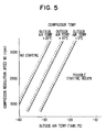
- Fig. 5 shows a second embodiment of the present invention.
- the suction pressure (PS) of the compressor 7 is determined as in the first embodiment.
- the compressor 7 may be more easily started as the temperature of the compressor increases.
- Fig. 6 shows a third embodiment of the present invention.
- control states identical to those in the flow diagram of Fig. 3 are denoted with identical numerals, and the corresponding description is omitted.
- a sensor signal from a not-shown refrigerant pressure switch (or refrigerant pressure sensor) is input to the air conditioning ECU 10. Therefore, it is possible to detect the suction pressure (PS) of the compressor 7.
- step S22 determines whether a result of the determination at step S22 is NO.
- TW cooling water temperature
- step S25 a predetermined temperature (for example 80°C)
- step S25 when the determination at step S25 is YES, the electromagnetic clutch (Mg/Cl) 8 is energized (ON) to thereby (re-)start the compressor 7, the first electromagnetic valve 23 is closed, the second electromagnetic valve 24 is opened, and thus the refrigerating cycle unit 20 is operated by the second refrigerant circuit 22 (step S26).
- step S27 it is determined whether the suction pressure (PS) of the compressor 7 detected by the pressure switch (or pressure sensor) is lower than a predetermined value (for example -0.5 kg/cm 2 G) (step S27). When this determination is NO, processing returns to step S22.
- a predetermined value for example -0.5 kg/cm 2 G
- the suction pressure (PS) of the compressor 7 is directly detected by the refrigerant pressure switch (or refrigerant pressure sensor).
- the detected suction pressure (PS) is lower than a predetermined value (for example -0.5 kg/cm 2 G)
- the electromagnetic clutch 8 is turned OFF to thereby automatically stop the compressor 7 (hot gas heater cycle).
- a predetermined time for example 60 seconds
- the electromagnetic clutch 8 is turned ON to thereby re-start the compressor 7.
- the hot gas heater cycle can be re-started after a predetermined time has elapsed from when the hot gas cycle is automatically stopped, when the hot-water heater 5 of the hot-water warming unit 4 utilizing the cooling water of the engine provides insufficient heating, the hot-water heater 5 is assisted by hot gas guided to the evaporator 6, so that the vehicle interior can be rapidly warmed after the hot-water warming unit 4 is started.
- the invention has been applied to a vehicle air conditioner refrigerating cycle apparatus, it may also be applied to the air conditioner refrigerating cycle apparatus of an airplane, a ship, a railway vehicle, and the like. Further, the invention may be applied to the air conditioner refrigerating cycle apparatus of a factory, a shop, a house, and the like.
Abstract
Description
- The present invention relates generally to vehicle air conditioning systems, and particularly to a refrigerating cycle apparatus in which a high temperature/high pressure gas refrigerant discharged from a refrigerant compressor is guided through a pressure reducer and then an internal heat exchanger to heat air flowing through an air conditioner duct.
- A conventional vehicle air conditioning system includes a hot-water warming unit in which engine cooling water is guided to a hot-water heater located in an air conditioning duct to heat air flowing through the duct. However, such a hot water warming unit is inefficient during engine startup when both outside air and cooling water temperatures are low.
- Japanese Patent Application Laid-Open No. Hei. 5-223357 describes a vehicle air conditioning apparatus having an auxiliary warming unit adapted to assist the main warming unit by guiding a high temperature/high pressure gas refrigerant discharged from an engine-driven refrigerant compressor to an internal heat exchanger via a pressure reducing unit, so that the heat exchanger heats the air flowing through an air conditioning duct.
- When cooling water temperature is higher than a predetermined temperature and the warming power of the main warming unit is sufficiently high, the vehicle interior is sufficiently heated, and the refrigerant compressor is turned OFF to stop the hot gas heater cycle. Further, when the cooling water temperature is lower than the predetermined temperature and the warming power of the main warming unit is therefore insufficient, the refrigerant compressor is turned ON to start the hot gas heater cycle.
- The hot gas heater cycle of the above system is adapted such that heat generated by compression work of the refrigerant compressor is radiated by a vehicle internal heat exchanger. The heat is radiated in a manner different from a typical heat pump cycle in which the vehicle internal heat exchanger functions as a refrigerant condenser, and in which a vehicle external heat exchanger functions as a refrigerant evaporator. Therefore, the cycle can operate even when the outside air temperature is very low, such as in the vicinity of -40°C.
- However, in the above heater cycle, when the outside temperature is around -20°C, negative pressure forms due to characteristics of refrigerant HFC-134a before the refrigerant compressor is started. Further, due to characteristics of the hot gas heater cycle, when the suction portion of the refrigerant compressor is at a negative pressure, suction pressure (PS) of a compressor suction portion just after the compressor starts typically decreases initially, as shown in Fig.7, before gradually increasing. As a conventional engine-driven refrigerant compressor typically has a weak shaft seal, if compressor suction pressure decreases below a predetermined value (for example -0.5 kg/cm2 G), air tends to penetrate into the compressor from the seal portion. Such air penetration is undesirable, as it tends to cause corrosion and high pressure to abnormally increase.
- In view of the above limitations of the prior art, it is an object of the present invention to inhibit air from penetrating into the refrigerant compressor when a second auxiliary refrigerant circuit is started during very low outside temperature conditions.
- More particularly, according to the present invention, when the second refrigerant circuit is started at a time of very low outside air temperature, when the physical quantity representative of a detected compressor suction pressure becomes less than a predetermined value, it is possible to prevent air from penetrating into the refrigerant compressor without improving the compressor shaft seal. Air penetration is prevented by controlling the refrigerant compressor to automatically stop the second refrigerant circuit. Further, since it is possible to prevent air from penetrating into the refrigerant compressor, corrosion and abnormally high pressure during first refrigerant circuit startup can be prevented.
- Further, when the second refrigerant circuit is started during very low outside air temperature conditions, after the suction pressure of the refrigerant compressor or the physical quantity representative of the suction pressure has become less than a predetermined value and the second refrigerant circuit has been automatically stopped, it is possible to assist the main warming unit by restarting the second refrigerant circuit after a predetermined elapsed time so that the vehicle interior can be rapidly warmed during initial startup of the main warming unit.
- Fig. 1 is a system diagram showing the structure of a vehicle air conditioning apparatus according to a first embodiment of the present invention;
- Fig. 2 is a block diagram showing a control system of the vehicle air conditioning apparatus in the first embodiment);
- Fig. 3 is a flow diagram illustrating compressor control methodology of an air conditioning ECU of the first embodiment;
- Fig. 4 is a graph showing a possible starting region of a compressor determined from compressor revolution speed and an outside air temperature in the first embodiment;
- Fig. 5 is a graph showing a possible starting region of a compressor determined from compressor revolution speed and an outside air temperature according to a second embodiment of the present invention;
- Fig. 6 is a flow diagram of compressor control methodology of an air conditioning ECU according to a third embodiment of the present invention; and
- Fig. 7 is a prior art timing diagram showing changes in a discharge pressure (PD) of a compressor just after the compressor is started, as well as a compressor suction pressure (PS).
-
- Referring to Figs. 1 - 4, a first embodiment of the present invention will now be described. A
vehicle air conditioner 1 according to the first embodiment includes an air conditioner control unit ECU 10. Theair conditioner 1 includes anair conditioning duct 2 forming anair passage 11 for guiding conditioned air into the interior of a vehicle. At an air downstream side of theair conditioning duct 2, an outside air suction port, an inside air suction port and an inside/outside air switching door (not shown) are provided. At an air upstream side, acentrifugal blower 3 and blow ports, such as a defroster blow port, a face blow port and a foot blow port, and a mode switching door (not shown) are provided. - The
centrifugal blower 3 is composed of a scroll casing provided integrally with theair conditioning duct 2, ablower motor 12 controlled by a blower driving circuit (not shown), and acentrifugal fan 13 rotatably driven by theblower motor 12 and having a blowing capacity that may be controlled in a continuous or stepwise manner. - At a blow port upstream side, a hot-
water heater 5 of a hot-water warming unit 4 re-heats air that has passed through anevaporator 6. The hot-water heater 5 is disposed at a middle location in acooling water circuit 14, through which a water pump (not shown) driven by a vehicle engine E circulates cooling water. If a hot-water valve 15 disposed in thecooling water circuit 14 is opened, the hot-water heater 5 causes the cooling water, having absorbed the engine exhaust heat of the engine E, to circulate therethrough. As a result, the air is re-heated so that the cooling water becomes a heat source. In other words, it acts as a downstream side, or second, heat exchanger for heating air. Preferably, the hot-water warming unit 4 is composed of the engine E, the hot-water heater 5, thecooling water circuit 14, and the hot-water valve 15. - Next, between the
centrifugal blower 3 and the hot-water heater 5, theevaporator 6, which forms one constituent part of a vehicle refrigeratingcycle unit 20, is disposed across theair passage 11 in theair conditioning duct 2. The refrigeratingcycle unit 20 also includes afirst refrigerant circuit 21, asecond refrigerant circuit 22, and first and secondelectromagnetic valves second refrigerant circuits - The
first refrigerant circuit 21 is for circulating a high temperature/high pressure gas refrigerant discharged from acompressor 7 in the following order: firstelectromagnetic valve 23;condenser 25;receiver 26;expansion valve 27;evaporator 6;accumulator 28; andcompressor 7. Further, thesecond refrigerant circuit 22 is for circulating a high temperature/high pressure gas refrigerant discharged from thecompressor 7 in the following order: secondelectromagnetic valve 24; pressure reducing unit; 29;evaporator 6;accumulator 28; andcompressor 7. - If the first
electromagnetic valve 23 is opened and the secondelectromagnetic valve 24 is closed, therefrigerating cycle unit 20 causes the refrigerant to circulate through thefirst refrigerant circuit 21. Further, if the firstelectromagnetic valve 23 is closed and the secondelectromagnetic valve 24 is opened, the refrigeratingcycle unit 20 causes the refrigerant to circulate through thesecond refrigerant circuit 22. Incidentally, the circuit switch includes the first and secondelectromagnetic valves numeral 16 denotes a cooling fan rotatably driven by adrive motor 17 that forcibly blows outside air to thecondenser 25. - The
evaporator 6 corresponds to an internal heat exchanger. When the refrigerant flows through thefirst refrigerant circuit 21, the evaporator causes a low temperature vapor/liquid two-phase refrigerant flowing into thecircuit 21 from theexpansion valve 27 to evaporate. Thus, theevaporator 6 functions as a cooling heat exchanger for cooling the air passing through it. - Further, when the refrigerant flows through the
second refrigerant circuit 22, theevaporator 6 functions as a first heating heat exchanger for heating the air passing through it by passing a high temperature gas refrigerant flowing into it from thepressure reducing unit 29. Here, theexpansion valve 27 not only causes the refrigerant to adibiatically expand but also adjusts a circulation amount of the refrigerant in compliance with a refrigerant overheat degree of an evaporator outlet. - The
compressor 7 is preferably an engine-driven piston-type fixed volume compressor which compresses the refrigerant sucked from its suction port and discharges a high temperature/high pressure gas refrigerant from its discharge port. Anelectromagnetic clutch 8 for transmitting or interrupting rotary power of the engine E to or from thecompressor 7 is connected to a shaft of thecompressor 7. Further, a belt V is rotated both by apulley 33 of theelectromagnetic clutch 8 and a crank pulley of the engine E, thereby facilitating transmission of the engine rotary power to thecompressor 7. - When the
electromagnetic clutch 8 is energized (ON), the engine rotary power is transmitted to thecompressor 7 via the belt V and theelectromagnetic clutch 8. The refrigeratingcycle unit 20 is started, and thus an air cooling action or an air heating action is performed by theevaporator 6. Further, when theelectromagnetic clutch 8 is de-energized (OFF), the rotary power of the engine E is not transmitted to thecompressor 7, and the air cooling or heating action is stopped. - Respective switch signals from respective switches on an air conditioning operation panel (not shown) provided in the vehicle passenger compartment are input to the
air conditioning ECU 10. A hot gas switch (S/W) 99, amode switching switch 100 for switching an air conditioning mode to a cooler mode or a heater mode, a temperature-setting switch 101 for setting a vehicle interior temperature to a desired temperature, anair conditioning switch 102 for starting or stopping the refrigeratingcycle unit 20, ablower switch 103 for turning thecentrifugal blower 3 ON/OFF, and the like are provided on the air conditioning operation panel. - Further, inside the
air conditioning ECU 10, a known microcomputer including a CPU, ROM, RAM and the like is provided, and respective sensor signals from respective sensors are input to the microcomputer after being A/D-converted by an input circuit (not shown). It should be appreciated that theair conditioning ECU 10 is programmed so that, when an ignition switch of the engine E is turned on (IG·ON), control processing is started. - Also, respective sensor signals from an inside
air temperature sensor 104 for detecting a vehicle interior air temperature, an outsideair temperature sensor 105 for detecting a vehicle external air temperature, and asolar energy sensor 106 for detecting an amount of solar energy coming into the vehicle interior are input to theECU 10. - Further, respective sensor signals from a
post-evaporator temperature sensor 107 for detecting the temperature of air just after having passed theevaporator 6, a coolingwater temperature sensor 108 for detecting the temperature of cooling water flowing into the hot-water heater 5, and arefrigerant pressure sensor 109 for detecting a high pressure (PD) of the refrigeratingcycle unit 20 are also input into theECU 10. - Incidentally, the respective switches and sensors detect air conditioning environmental factors required for air-conditioning the vehicle interior, and thermistors are preferably used for the inside
air temperature sensor 104, the outsideair temperature sensor 105, thepost-evaporator temperature sensor 107, and the coolingwater temperature sensor 108. Further, theair conditioning ECU 10 has a revolution speed detector which inputs an engine revolution speed sensor signal (not shown) and thereby operates the compressor revolution speed. - Next, an ECU warming mode according to the present embodiment will be described with reference to Figs. 1 - 3.
- If the ignition switch is turned on (IG·ON), the control methodology shown in Fig. 3 is started. First, the respective signals are read from the respective switches on the air conditioning operation panel (step S1). More particularly, an ON or OFF signal of the hot gas S/
W 99 and a set state (cooler mode or heater mode) of themode switching switch 100 are read. - Next, the respective sensor signals are read (step S2). More specifically, an outside air temperature (TAM) detected by the outside
air temperature sensor 105, a cooling water temperature (TW) detected by the coolingwater temperature sensor 108, and a discharge pressure (PD) of thecompressor 7 detected by therefrigerant pressure sensor 109 are read. Further, based on an engine revolution speed input from the engine revolution speed sensor, a revolution speed (NC) of thecompressor 7 is computed and read. - Next, it is determined whether the air conditioning mode is a heater mode. That is, it is determined whether a heater mode is set by the mode switching switch 100 (step S3). When the result of this determination is NO, i.e., when the air conditioning mode is a cooler mode, the electromagnetic clutch (Mg/Cl) 8 is energized (ON) to thereby start the
compressor 7, the firstelectromagnetic valve 23 is opened, the secondelectromagnetic valve 24 is closed, and the refrigeratingcycle unit 20 is operated by the first refrigerant circuit 21 (step S4). Thereafter, the routine of Fig. 3 is exited. - Further, when the determination at step S3 is YES, i.e., when the mode is a heater mode, it is determined whether the
hot gas switch 99 is turned on (ON) (step S5). When this determination is NO, the electromagnetic clutch (Mg/Cl) 8 is de-energized (OFF) to thereby automatically stop thecompressor 7, and the first and secondelectromagnetic valves - Further, when a result of the determination at step S5 is YES, i.e., when the hot gas switch is ON, it is determined whether the cooling water temperature (TW) is equal to or less than a predetermined temperature (for example 80°C) (step S7). When the determination is NO, control processing proceeds to step S6.
- Further, when the determination at step S7 is YES, a suction pressure (PS) of the
compressor 7 is computed. More specifically, the suction pressure (PS) of thecompressor 7 is presumed from a revolution speed (NC) of thecompressor 7 computed based on a sensor signal from the engine revolution speed sensor, and from an outside air temperature (TAM) detected by the outside air temperature sensor 105 (step S8). - Based on the suction pressure (PS) of the
compressor 7 at step S8, a possible starting region is determined, within which if thecompressor 7 is started, a suction portion of thecompressor 7 at a positive pressure so that air penetration through shaft seal portion of thecompressor 7 is inhibited (step S9). - Next, it is determined whether the suction pressure (PS) of the
compressor 7 determined at step S8 is equal to or higher than a predetermined value (for example -0.5 kg/cm2 G). More particularly, it is determined whether the outside air temperature (TAM) or the revolution speed (NC) of thecompressor 7 is within the possible starting region of the compressor 7 (step S10). When a result of this determination is NO, processing proceeds to step S6. - Further, when a result of the determination at step S10 is YES, the electromagnetic clutch (Mg/Cl) 8 is energized (ON) to thereby (re-)start the
compressor 7, the firstelectromagnetic valve 23 is closed, the secondelectromagnetic valve 24 is opened, and thus the refrigeratingcycle unit 20 is operated by the second refrigerant circuit 22 (step S11). Thereafter, the routine of Fig. 3 is exited. - Next, operational modes of the vehicle air conditioning apparatus of this embodiment are briefly described based on Figs. 1 - 4.
- When the air conditioning mode is a cooler mode, the
electromagnetic clutch 8 is ON, the firstelectromagnetic valve 23 is opened, and the secondelectromagnetic valve 24 is closed. Therefore, a high temperature/high pressure gas refrigerant discharged from thecompressor 7 circulates through the firstrefrigerant circuit 21 and flows into theevaporator 6. The air sucked into theair conditioning duct 2 is cooled by being heat-exchanged with a low temperature/low pressure refrigerant in theevaporator 6, and is blown into a vehicle interior. As a result, the vehicle interior is cooled. - When the air conditioning mode is a heater mode, the
hot gas switch 99 is ON. When the cooling water temperature (TW) is equal to or lower than a predetermined temperature (for example 80°C) and thus the hot-water warming unit 4 cannot heat the vehicle interior sufficiently and it is within a possible starting region of thecompressor 7, theelectromagnetic clutch 8 is turned ON, the firstelectromagnetic valve 23 is closed and the secondelectromagnetic valve 24 is opened. Further, the hot-water valve 15 is opened as well. - Therefore, the high temperature/high pressure gas refrigerant discharged from the
compressor 7 circulates through the secondrefrigerant circuit 22 and flows into theevaporator 6. Further, the cooling water, having absorbed the exhaust heat of the engine E, circulates through the coolingwater circuit 14 and flows into the hot-water heater 5. The air sucked into theair conditioning duct 2 is heated by being heat-exchanged with a high temperature/low pressure refrigerant in theevaporator 6 and is further heated by being heat-exchanged with a high temperature cooling water in the hot-water heater 5 and blown into a vehicle interior. As a result, the vehicle interior is warmed. - As shown in Fig. 4, the possible compressor starting region in this embodiment is decided by determining the suction pressure (PS) of the
compressor 7 from, for example, the revolution speed (NC) of thecompressor 7 and the outside air temperature (TAM). - When, for example, the outside air temperature is -30°C and the revolution speed of the
compressor 7 is 1000 rpm, it is determined that the suction pressure (PS) of thecompressor 7 is a predetermined value (for example -0.5 kg/cm2 G). Therefore, if the revolution speed of thecompressor 7 is 1000 rpm and the outside air temperature is lower than -30°C, or if the outside air temperature is -30°C and the revolution speed of thecompressor 7 is higher than 1000 rpm, the compressor is automatically stopped (caused not to start), as the probability that a suction portion of thecompressor 7 is at a negative pressure when starting thecompressor 7 is high. - When the outside air temperature is -20°C and the revolution speed of the
compressor 7 is 3000 rpm, it is predicted that the suction pressure (PS) of thecompressor 7 is a predetermined value (for example -0.5 kg/cm2 G). Therefore, if thecompressor 7 is operating at 3000 rpm and the outside air temperature is lower than -20°C, or if the outside air temperature is -20°C and the speed of thecompressor 7 is higher than 3000 rpm, the compressor is automatically stopped (caused not to start), as the probability that a suction portion of thecompressor 7 is at a negative pressure during startup is high. - As mentioned above, when the second refrigerant circuit (hot gas heater cycle) 22 is started during very low outside air temperature conditions (lower than -20°C, for example), when a physical quantity representative of the suction pressure of the
compressor 7 is less than a predetermined value, the suction pressure of thecompressor 7 is prevented from decreasing just after thecompressor 7 is started by automatically stopping thecompressor 7 to thereby stop an auxiliary warming operation, so that a negative pressure condition at the suction portion of thecompressor 7 can be prevented. - Therefore, it is possible to prevent air from penetrating into the
compressor 7 without having to modify the shaft seal portion, etc. of thecompressor 7. Consequently, it is possible to inhibit cycle corrosion. Additionally, it is possible to prevent an abnormally high pressure state from occurring during first refrigerant circuit startup when the operating mode is in a cooler mode. - Fig. 5 shows a second embodiment of the present invention. In this embodiment, the suction pressure (PS) of the
compressor 7 is determined as in the first embodiment. By correcting a determined possible starting region based on a temperature of thecompressor 7 or a physical quantity corresponding to a temperature of the compressor 7 (for example, engine temperature, cooling water temperature, oil temperature, refrigerant pressure when the secondrefrigerant circuit 22 is stopped, and the like), thecompressor 7 may be more easily started as the temperature of the compressor increases. - Fig. 6 shows a third embodiment of the present invention. Here, control states identical to those in the flow diagram of Fig. 3 are denoted with identical numerals, and the corresponding description is omitted.
- In this embodiment, a sensor signal from a not-shown refrigerant pressure switch (or refrigerant pressure sensor) is input to the
air conditioning ECU 10. Therefore, it is possible to detect the suction pressure (PS) of thecompressor 7. - In this embodiment, when a result of the determination in the step S5 is YES, i.e., when the
hot gas switch 99 is ON, a timer circuit is reset (I = 0) and started (step S21). Next, it is determined whether the count (I) of the timer circuit is at or between 1 and 60 seconds (step S22). When a result of this determination is YES, the count (I) of the timer circuit is renewed (I = I + 1) (step S23). Thereafter, control returns to the determination processing at step S22. - Further, when a result of the determination at step S22 is NO, the timer circuit is reset (I = 0) and then started (step S24). Next, it is determined whether the cooling water temperature (TW) is lower than a predetermined temperature (for example 80°C) (step S25). When this determination is NO, control processing proceeds to step S6.
- Further, when the determination at step S25 is YES, the electromagnetic clutch (Mg/Cl) 8 is energized (ON) to thereby (re-)start the
compressor 7, the firstelectromagnetic valve 23 is closed, the secondelectromagnetic valve 24 is opened, and thus the refrigeratingcycle unit 20 is operated by the second refrigerant circuit 22 (step S26). - Next, it is determined whether the suction pressure (PS) of the
compressor 7 detected by the pressure switch (or pressure sensor) is lower than a predetermined value (for example -0.5 kg/cm2 G) (step S27). When this determination is NO, processing returns to step S22. - Further, when the determination at
step 27 is YES, the electromagnetic clutch (Mg/Cl) 8 is de-energized (OFF) to thereby automatically stop thecompressor 7, and the first and secondelectromagnetic valves - As mentioned above, in this embodiment, the suction pressure (PS) of the
compressor 7 is directly detected by the refrigerant pressure switch (or refrigerant pressure sensor). When the detected suction pressure (PS) is lower than a predetermined value (for example -0.5 kg/cm2 G), theelectromagnetic clutch 8 is turned OFF to thereby automatically stop the compressor 7 (hot gas heater cycle). Further, after a predetermined time (for example 60 seconds) has elapsed from when the hot gas heater cycle is automatically stopped, theelectromagnetic clutch 8 is turned ON to thereby re-start thecompressor 7. - Therefore, since the hot gas heater cycle can be re-started after a predetermined time has elapsed from when the hot gas cycle is automatically stopped, when the hot-
water heater 5 of the hot-water warming unit 4 utilizing the cooling water of the engine provides insufficient heating, the hot-water heater 5 is assisted by hot gas guided to theevaporator 6, so that the vehicle interior can be rapidly warmed after the hot-water warming unit 4 is started. - Although the invention has been applied to a vehicle air conditioner refrigerating cycle apparatus, it may also be applied to the air conditioner refrigerating cycle apparatus of an airplane, a ship, a railway vehicle, and the like. Further, the invention may be applied to the air conditioner refrigerating cycle apparatus of a factory, a shop, a house, and the like.
- While the above description constitutes the preferred embodiment of the present invention, the invention may be modified without departing from the proper scope or fair meaning of the accompanying claims. Various other advantages of the present invention will become apparent to those skilled in the art after having the benefit of studying the foregoing text and drawings taken in conjunction with the following claims.
Claims (19)
- A refrigerating cycle apparatus comprising:a first refrigerant circuit (21) respectively including a refrigerant compressor (7) for discharging a high temperature refrigerant, an external heat exchanger (25) for receiving the discharged refrigerant, first pressure reducing means (27), and an internal heat exchanger (6) for cooling air prior to the refrigerant being returned to the refrigerant compressor (7);a second refrigerant circuit (22) respectively including second pressure reducing means (29) and the internal heat exchanger (6) for heating the conditioned air prior to the refrigerant being returned to the refrigerant compressor (7), the second refrigerant circuit (22) bypassing the external heat exchanger (25);suction pressure detection means for detecting a physical quantity representative of a suction pressure of the refrigerant compressor (7); andair conditioning control means (10) for controlling the refrigerant compressor (7) such that the second refrigerant circuit (22) is automatically stopped when the physical quantity detected by the suction pressure detection means is less than a predetermined value.
- The refrigerating cycle apparatus of claim 1, wherein the air conditioning control means (10) controls the refrigerant compressor (7) such that the second refrigerant circuit (22) is re-started after a predetermined elapsed time after being automatically stopped.
- The refrigerating cycle apparatus of claim 1, wherein the suction pressure detection means includes outside air temperature detection means (105) for detecting an outside air temperature, and revolution speed detection means (110) for detecting a revolution speed of the refrigerant compressor (7); and
the suction pressure detection means determines the suction pressure of the refrigerant compressor (7) based on the detected outside air temperature and the detected compressor speed, sets a possible starting region of the refrigerant compressor (7) based on the determined suction pressure, and controls the refrigerant compressor (7) such that the second refrigerant circuit (22) is started only in the possible starting region. - The refrigerating cycle apparatus of claim 3, wherein the suction pressure detection means corrects the possible starting region based on a physical quantity representing a temperature of the refrigerant compressor (7).
- The refrigerating cycle apparatus of claim 4, wherein the physical quantity representing the temperature of the compressor (7) is selected from the group consisting of: an engine cooling water temperature, an engine lubricating oil temperature, and a refrigerant pressure in the first and second refrigerant circuits.
- A refrigerating cycle apparatus comprising:a first refrigerant circuit (21) including a refrigerant compressor (7), and an internal heat exchanger (6) for cooling air prior to refrigerant being returned to the refrigerant compressor (7);a second refrigerant circuit (22) respectively including the internal heat exchanger (6) for heating the conditioned air prior to the refrigerant being returned to the refrigerant compressor (7);a suction pressure detector for detecting a physical quantity representative of a suction pressure of the refrigerant compressor (7); anda compressor controller (10) for selectively controlling operation of the first and second refrigerant circuits (21, 22) based on the physical quantity detected by the suction pressure detector.
- The refrigerating cycle apparatus of claim 6, wherein the first refrigerant circuit (21) includes an external heat exchanger (25), and the second refrigerant circuit (22) bypasses the external heat exchanger (25).
- The refrigerating cycle apparatus of claim 6, further comprising a switching circuit (23, 24) controlled by the controller (10) for switching operation of the first and second refrigerant circuits (21, 22).
- The refrigerating cycle apparatus of claim 6, further comprising a cooling water circuit (4) for heating the air with heated engine cooling water, wherein the controller (10) activates the second refrigerant circuit (22) when the temperature of the cooling water in the cooling water circuit (4) is below a predetermined value in an air heating mode.
- The refrigerating cycle apparatus of claim 9, wherein the controller (10) activates the second refrigerant circuit (22) only when a possible compressor starting region exists.
- The refrigerating cycle apparatus of claim 10, wherein the possible compressor starting region exists when a compressor suction pressure falls within a predetermined range.
- The refrigerating cycle apparatus of claim 11, wherein the possible compressor starting region is corrected based on one of a compressor temperature and a physical quantity corresponding to the compressor temperature.
- The refrigerating cycle apparatus of claim 6, wherein the compressor controller (10) selectively controls operation of the first and second refrigerant circuits (21, 22) based on compressor suction pressure detected directly by the suction pressure detector.
- The refrigerating cycle apparatus of claim 13, wherein the controller (10) automatically stops the compressor (7) and the first and second refrigerant circuits (21, 22) for a predetermined time when the suction pressure is below a predetermined level.
- A method of controlling operation of an auxiliary air heating circuit (22) in a vehicle air conditioning system (1) including a primary air heating circuit (4) and the auxiliary air heating circuit (22), wherein the auxiliary air heating circuit (22) circulates refrigerant discharged from a compressor (7), the method comprising the steps of:monitoring a system operating mode (S1-S5);determining a temperature of engine cooling water circulating through the primary air heating circuit when the step of monitoring indicates that the system operating mode is a heating mode (S7);determining if compressor operating parameters of the auxiliary air heating circuit falls within a predetermined compressor starting range (S8-S10); andstarting the auxiliary air heating circuit compressor when the compressor operating parameters fall within the predetermined compressor starting range (S11).
- The method of claim 15, wherein the step of determining if a compressor suction pressure of the auxiliary air heating circuit falls within a predetermined compressor starting range comprises:measuring outside air temperature and compressor revolution speed; andestimating compressor suction pressure from the outside air temperature and the compressor revolution speed.
- The method of claim 16, further comprising the step of correcting the predetermined compressor starting range based on one of a temperature of the compressor and a physical quantity corresponding to the temperature of the compressor.
- The method of claim 15, further comprising the step of directly measuring the compressor suction pressure prior to the step of determining if a compressor suction pressure of the auxiliary air heating circuit falls within a predetermined compressor starting range (S27).
- The method of claim 18, further comprising stopping the compressor and the auxiliary refrigerant circuit for a predetermined time when the suction pressure is below a predetermined level (S28).
Applications Claiming Priority (2)
| Application Number | Priority Date | Filing Date | Title |
|---|---|---|---|
| JP31786098A JP4003320B2 (en) | 1998-11-09 | 1998-11-09 | Refrigeration cycle equipment |
| JP31786098 | 1998-11-09 |
Publications (3)
| Publication Number | Publication Date |
|---|---|
| EP1000787A2 true EP1000787A2 (en) | 2000-05-17 |
| EP1000787A3 EP1000787A3 (en) | 2002-06-19 |
| EP1000787B1 EP1000787B1 (en) | 2003-10-08 |
Family
ID=18092877
Family Applications (1)
| Application Number | Title | Priority Date | Filing Date |
|---|---|---|---|
| EP99120937A Expired - Lifetime EP1000787B1 (en) | 1998-11-09 | 1999-11-02 | Vehicle refrigerating cycle apparatus and method for inhibiting cycle corrosion and for facilitating rapid passenger compartment warm-up during low temperature conditions |
Country Status (4)
| Country | Link |
|---|---|
| US (1) | US6237681B1 (en) |
| EP (1) | EP1000787B1 (en) |
| JP (1) | JP4003320B2 (en) |
| DE (1) | DE69911885T2 (en) |
Cited By (2)
| Publication number | Priority date | Publication date | Assignee | Title |
|---|---|---|---|---|
| CN105270134A (en) * | 2014-05-27 | 2016-01-27 | 现代自动车株式会社 | System and method for controlling air flow in vehicle |
| CN105352212A (en) * | 2015-11-30 | 2016-02-24 | 江苏博莱客冷冻科技发展有限公司 | Continuous generation device and preparation method for low-temperature air |
Families Citing this family (22)
| Publication number | Priority date | Publication date | Assignee | Title |
|---|---|---|---|---|
| CN1133047C (en) * | 2001-03-14 | 2003-12-31 | 清华同方股份有限公司 | Heat pump air conditioners suitable for cold area |
| JP4661011B2 (en) * | 2001-09-10 | 2011-03-30 | 株式会社デンソー | Air conditioner for vehicles |
| JP4085694B2 (en) * | 2002-02-27 | 2008-05-14 | 株式会社デンソー | Air conditioner |
| DE60300058T2 (en) * | 2002-03-18 | 2006-02-23 | Denso Corp., Kariya | An automotive air conditioning system |
| JP3990593B2 (en) * | 2002-05-09 | 2007-10-17 | 本田技研工業株式会社 | Heat pump air conditioner for vehicles |
| KR100917173B1 (en) | 2003-01-29 | 2009-09-15 | 한라공조주식회사 | Cooling and heating system for vehicle |
| JP2004338447A (en) * | 2003-05-13 | 2004-12-02 | Denso Corp | Air conditioner |
| DE10332157A1 (en) * | 2003-06-26 | 2005-01-13 | Behr Gmbh & Co. Kg | Device for cooling or heating a closed room and method for operating such a device |
| US7178353B2 (en) * | 2004-02-19 | 2007-02-20 | Advanced Thermal Sciences Corp. | Thermal control system and method |
| JP2005351286A (en) * | 2004-06-08 | 2005-12-22 | Shin Caterpillar Mitsubishi Ltd | Controller of i/o rotational speed ratio variable type clutch |
| JP3891196B2 (en) * | 2004-11-25 | 2007-03-14 | ダイキン工業株式会社 | Refrigeration equipment |
| JP4375437B2 (en) | 2007-05-28 | 2009-12-02 | 株式会社デンソー | Compressor suction pressure estimation device for refrigeration cycle equipment |
| JP4380730B2 (en) | 2007-05-28 | 2009-12-09 | 株式会社デンソー | Compressor suction pressure estimation device for refrigeration cycle equipment |
| FR2937906B1 (en) * | 2008-11-03 | 2010-11-19 | Arkema France | METHOD FOR HEATING AND / OR AIR CONDITIONING A VEHICLE |
| US20170080773A1 (en) | 2008-11-03 | 2017-03-23 | Arkema France | Vehicle Heating and/or Air Conditioning Method |
| US9453669B2 (en) * | 2009-12-08 | 2016-09-27 | Thermo King Corporation | Method of controlling inlet pressure of a refrigerant compressor |
| US9925877B2 (en) | 2011-01-21 | 2018-03-27 | Sanden Holdings Corporation | Vehicle air conditioning apparatus |
| US10160291B2 (en) | 2011-01-21 | 2018-12-25 | Sanden Holdings Corporation | Vehicle air conditioning apparatus |
| JP5851703B2 (en) * | 2011-02-25 | 2016-02-03 | サンデンホールディングス株式会社 | Air conditioner for vehicles |
| JP5851696B2 (en) * | 2011-01-21 | 2016-02-03 | サンデンホールディングス株式会社 | Air conditioner for vehicles |
| WO2015011920A1 (en) | 2013-07-26 | 2015-01-29 | パナソニックIpマネジメント株式会社 | Air conditioning device for vehicle |
| US10041552B2 (en) * | 2015-07-16 | 2018-08-07 | Ford Global Technologies, Llc | Methods and systems for controlling a vehicle air conditioner using a pressure sensor located within a compressor |
Citations (1)
| Publication number | Priority date | Publication date | Assignee | Title |
|---|---|---|---|---|
| JPH05223357A (en) | 1991-06-24 | 1993-08-31 | Nippondenso Co Ltd | Air conditioning device |
Family Cites Families (7)
| Publication number | Priority date | Publication date | Assignee | Title |
|---|---|---|---|---|
| US2363273A (en) * | 1943-06-02 | 1944-11-21 | Buensod Stacey Inc | Refrigeration |
| JPH04124479A (en) * | 1990-09-13 | 1992-04-24 | Toyota Autom Loom Works Ltd | Compressor |
| GB2272506B (en) * | 1992-11-02 | 1996-07-24 | Nippon Denso Co | Refrigerant condenser |
| JPH1076841A (en) * | 1996-09-06 | 1998-03-24 | Calsonic Corp | Heat pump type air conditioner for automobile |
| EP0842799A3 (en) * | 1996-11-15 | 2003-03-05 | Calsonic Kansei Corporation | Heat pump type air conditioning system for automotive vehicle |
| US6076366A (en) * | 1998-04-03 | 2000-06-20 | Denso Corporation | Refrigerating cycle system with hot-gas bypass passage |
| JP3386014B2 (en) * | 1998-11-25 | 2003-03-10 | 株式会社デンソー | Refrigeration cycle device |
-
1998
- 1998-11-09 JP JP31786098A patent/JP4003320B2/en not_active Expired - Fee Related
-
1999
- 1999-10-25 US US09/427,395 patent/US6237681B1/en not_active Expired - Lifetime
- 1999-11-02 EP EP99120937A patent/EP1000787B1/en not_active Expired - Lifetime
- 1999-11-02 DE DE69911885T patent/DE69911885T2/en not_active Expired - Lifetime
Patent Citations (1)
| Publication number | Priority date | Publication date | Assignee | Title |
|---|---|---|---|---|
| JPH05223357A (en) | 1991-06-24 | 1993-08-31 | Nippondenso Co Ltd | Air conditioning device |
Cited By (3)
| Publication number | Priority date | Publication date | Assignee | Title |
|---|---|---|---|---|
| CN105270134A (en) * | 2014-05-27 | 2016-01-27 | 现代自动车株式会社 | System and method for controlling air flow in vehicle |
| CN105352212A (en) * | 2015-11-30 | 2016-02-24 | 江苏博莱客冷冻科技发展有限公司 | Continuous generation device and preparation method for low-temperature air |
| CN105352212B (en) * | 2015-11-30 | 2018-05-22 | 江苏博莱客冷冻科技发展有限公司 | A kind of Cryogenic air continuous generator and preparation method |
Also Published As
| Publication number | Publication date |
|---|---|
| DE69911885D1 (en) | 2003-11-13 |
| EP1000787A3 (en) | 2002-06-19 |
| DE69911885T2 (en) | 2004-05-19 |
| US6237681B1 (en) | 2001-05-29 |
| EP1000787B1 (en) | 2003-10-08 |
| JP4003320B2 (en) | 2007-11-07 |
| JP2000142094A (en) | 2000-05-23 |
Similar Documents
| Publication | Publication Date | Title |
|---|---|---|
| US6237681B1 (en) | Vehicle refrigerating cycle apparatus and method for inhibiting cycle corrosion and for facilitating rapid passenger compartment warm-up during low temperature conditions | |
| US7398653B2 (en) | Air conditioner for vehicle capable of preventing inverter overheating | |
| US7174733B2 (en) | Vehicular air-conditioner | |
| US7207379B2 (en) | Automotive air conditioning system | |
| US5918475A (en) | Air conditioning apparatus for vehicle, using a flammable refrigerant | |
| US9797641B2 (en) | Vehicular air-conditioning device | |
| JPH07294071A (en) | Air conditioner for automobile | |
| JP4443812B2 (en) | Air conditioner for vehicles | |
| US6725676B2 (en) | Refrigerant cycle system with hot gas heating function | |
| JP2002370529A (en) | Air-conditioner for vehicle | |
| JP3794115B2 (en) | Air conditioner | |
| JP3617143B2 (en) | Air conditioner for vehicles | |
| GB2395776A (en) | Vehicle air conditioner having a refrigerant cycle with heating function | |
| JP2004182165A (en) | Air conditioner for vehicle | |
| JP3767050B2 (en) | Air conditioner for vehicles | |
| JPH1142934A (en) | Air conditioner | |
| JP3794078B2 (en) | Air conditioner for vehicles | |
| JP2003136944A (en) | Air-conditioner device for vehicle | |
| JP3858738B2 (en) | Air conditioner for vehicles | |
| KR100928000B1 (en) | Heating control method of air conditioner for automobile | |
| JP2007327701A (en) | Refrigerating cycle device | |
| JP2003269810A (en) | Air conditioner | |
| JP2007022180A (en) | Air-conditioner for vehicle and method of controlling air-conditioning for vehicle | |
| JPH10181339A (en) | Air conditioner | |
| JP2007320377A (en) | Vehicular air conditioner |
Legal Events
| Date | Code | Title | Description |
|---|---|---|---|
| PUAI | Public reference made under article 153(3) epc to a published international application that has entered the european phase |
Free format text: ORIGINAL CODE: 0009012 |
|
| AK | Designated contracting states |
Kind code of ref document: A2 Designated state(s): AT BE CH CY DE DK ES FI FR GB GR IE IT LI LU MC NL PT SE |
|
| AX | Request for extension of the european patent |
Free format text: AL;LT;LV;MK;RO;SI |
|
| PUAL | Search report despatched |
Free format text: ORIGINAL CODE: 0009013 |
|
| AK | Designated contracting states |
Kind code of ref document: A3 Designated state(s): AT BE CH CY DE DK ES FI FR GB GR IE IT LI LU MC NL PT SE |
|
| AX | Request for extension of the european patent |
Free format text: AL;LT;LV;MK;RO;SI |
|
| RIC1 | Information provided on ipc code assigned before grant |
Free format text: 7B 60H 1/32 A, 7B 60H 1/00 B, 7F 25B 41/04 B |
|
| 17P | Request for examination filed |
Effective date: 20020801 |
|
| 17Q | First examination report despatched |
Effective date: 20021002 |
|
| AKX | Designation fees paid |
Designated state(s): DE FR GB IT |
|
| GRAH | Despatch of communication of intention to grant a patent |
Free format text: ORIGINAL CODE: EPIDOS IGRA |
|
| GRAS | Grant fee paid |
Free format text: ORIGINAL CODE: EPIDOSNIGR3 |
|
| GRAA | (expected) grant |
Free format text: ORIGINAL CODE: 0009210 |
|
| AK | Designated contracting states |
Kind code of ref document: B1 Designated state(s): DE FR GB IT |
|
| REG | Reference to a national code |
Ref country code: GB Ref legal event code: FG4D |
|
| REG | Reference to a national code |
Ref country code: IE Ref legal event code: FG4D |
|
| REF | Corresponds to: |
Ref document number: 69911885 Country of ref document: DE Date of ref document: 20031113 Kind code of ref document: P |
|
| ET | Fr: translation filed | ||
| PLBE | No opposition filed within time limit |
Free format text: ORIGINAL CODE: 0009261 |
|
| STAA | Information on the status of an ep patent application or granted ep patent |
Free format text: STATUS: NO OPPOSITION FILED WITHIN TIME LIMIT |
|
| REG | Reference to a national code |
Ref country code: IE Ref legal event code: MM4A |
|
| 26N | No opposition filed |
Effective date: 20040709 |
|
| REG | Reference to a national code |
Ref country code: GB Ref legal event code: 746 Effective date: 20050210 |
|
| PGFP | Annual fee paid to national office [announced via postgrant information from national office to epo] |
Ref country code: GB Payment date: 20091028 Year of fee payment: 11 Ref country code: FR Payment date: 20091123 Year of fee payment: 11 |
|
| PGFP | Annual fee paid to national office [announced via postgrant information from national office to epo] |
Ref country code: IT Payment date: 20091113 Year of fee payment: 11 |
|
| GBPC | Gb: european patent ceased through non-payment of renewal fee |
Effective date: 20101102 |
|
| REG | Reference to a national code |
Ref country code: FR Ref legal event code: ST Effective date: 20110801 |
|
| PG25 | Lapsed in a contracting state [announced via postgrant information from national office to epo] |
Ref country code: FR Free format text: LAPSE BECAUSE OF NON-PAYMENT OF DUE FEES Effective date: 20101130 |
|
| PG25 | Lapsed in a contracting state [announced via postgrant information from national office to epo] |
Ref country code: GB Free format text: LAPSE BECAUSE OF NON-PAYMENT OF DUE FEES Effective date: 20101102 |
|
| PG25 | Lapsed in a contracting state [announced via postgrant information from national office to epo] |
Ref country code: IT Free format text: LAPSE BECAUSE OF NON-PAYMENT OF DUE FEES Effective date: 20101102 |
|
| PGFP | Annual fee paid to national office [announced via postgrant information from national office to epo] |
Ref country code: DE Payment date: 20121031 Year of fee payment: 14 |
|
| REG | Reference to a national code |
Ref country code: DE Ref legal event code: R119 Ref document number: 69911885 Country of ref document: DE Effective date: 20140603 |
|
| PG25 | Lapsed in a contracting state [announced via postgrant information from national office to epo] |
Ref country code: DE Free format text: LAPSE BECAUSE OF NON-PAYMENT OF DUE FEES Effective date: 20140603 |