EP1000375B1 - Optical device for helmet visor comprising aspheric mirror - Google Patents
Optical device for helmet visor comprising aspheric mirror Download PDFInfo
- Publication number
- EP1000375B1 EP1000375B1 EP98941474A EP98941474A EP1000375B1 EP 1000375 B1 EP1000375 B1 EP 1000375B1 EP 98941474 A EP98941474 A EP 98941474A EP 98941474 A EP98941474 A EP 98941474A EP 1000375 B1 EP1000375 B1 EP 1000375B1
- Authority
- EP
- European Patent Office
- Prior art keywords
- mirror
- image
- axis
- aspherical
- user
- Prior art date
- Legal status (The legal status is an assumption and is not a legal conclusion. Google has not performed a legal analysis and makes no representation as to the accuracy of the status listed.)
- Expired - Lifetime
Links
Images


Classifications
-
- G—PHYSICS
- G02—OPTICS
- G02B—OPTICAL ELEMENTS, SYSTEMS OR APPARATUS
- G02B17/00—Systems with reflecting surfaces, with or without refracting elements
- G02B17/08—Catadioptric systems
- G02B17/0804—Catadioptric systems using two curved mirrors
- G02B17/0816—Catadioptric systems using two curved mirrors off-axis or unobscured systems in which not all of the mirrors share a common axis of rotational symmetry, e.g. at least one of the mirrors is warped, tilted or decentered with respect to the other elements
-
- G—PHYSICS
- G02—OPTICS
- G02B—OPTICAL ELEMENTS, SYSTEMS OR APPARATUS
- G02B27/00—Optical systems or apparatus not provided for by any of the groups G02B1/00 - G02B26/00, G02B30/00
- G02B27/0081—Optical systems or apparatus not provided for by any of the groups G02B1/00 - G02B26/00, G02B30/00 with means for altering, e.g. enlarging, the entrance or exit pupil
-
- G—PHYSICS
- G02—OPTICS
- G02B—OPTICAL ELEMENTS, SYSTEMS OR APPARATUS
- G02B27/00—Optical systems or apparatus not provided for by any of the groups G02B1/00 - G02B26/00, G02B30/00
- G02B27/01—Head-up displays
- G02B27/017—Head mounted
- G02B27/0172—Head mounted characterised by optical features
-
- G—PHYSICS
- G02—OPTICS
- G02B—OPTICAL ELEMENTS, SYSTEMS OR APPARATUS
- G02B27/00—Optical systems or apparatus not provided for by any of the groups G02B1/00 - G02B26/00, G02B30/00
- G02B27/01—Head-up displays
- G02B27/0101—Head-up displays characterised by optical features
- G02B2027/011—Head-up displays characterised by optical features comprising device for correcting geometrical aberrations, distortion
Definitions
- the present invention relates to an optical device for correcting the image of the pupil of the eye given by a concave spherical mirror. More specifically, a device according to the invention makes it possible to observe an image which is corrected for distortion due to a spherical concave mirror, or substantially spherical, inclined relative to the direction in which the eye observe this mirror.
- the invention applies to a helmet viewfinder in particular, but not exclusively, for pilot of aircraft or helicopter weapons or for operator of a training simulator.
- a helmet viewfinder is an image presentation device integrated into a helmet.
- the viewfinder allows the wearer of the helmet, as by example an airplane pilot in flight, observing visual information simultaneously with the view of the landscape, or of the cockpit, that he perceives the more often through a protective visor.
- the information can also consist of a landscape image acquired by sensors different from the eye of the helmet wearer like infrared sensors or visible light intensifiers for complete or replace the direct view.
- an image generator Inside the helmet, an image generator includes an imager like for example a cathode ray tube screen or a crystal screen liquids on the screen of which an image is formed.
- an imager like for example a cathode ray tube screen or a crystal screen liquids on the screen of which an image is formed.
- the helmet most often includes a relay optic for transport this image to a combiner which provides a presentation of the image transported on top of the landscape view.
- collimation of the image can be achieved by an optical placed between the combiner and the imager; such an embodiment of the prior art has the main drawback of requiring collimation optics too cumbersome in relation to the restricted field of view provided.
- a spherical mirror concave achieves a medium quality collimation of an image placed in a particular point in space located on the axis of the mirror and at a distance of this one equal to half of its radius of curvature.
- the eye located on the axis of the mirror receives rays from the imager after their reflection on the spherical mirror, these rays are parallel and lead to the perception by the eye of a collimated image.
- the mirror is semi-reflecting, it allows the same eye to observe the landscape by transparency.
- the imager is found on the axis of the semi-transparent spherical mirror and it hides the field user view.
- the spherical mirror can be tilted relative to normal to the face and the user's eye is no longer on the axis of the mirror.
- This inclination has the major drawback of lead to a collimated image affected by optical aberrations, of eccentricity in particular, limiting too strongly the exploitation of such device.
- the prior art teaches us the use of a parabolic mirror instead of a spherical mirror.
- the imager is placed at the focus of the paraboloid described by the mirror and the eye observes the mirror along a parallel to the axis of paraboloid revolution.
- the collimated image perceived by the eye is devoid of aberration spherical but remains mainly affected by a very penalizing coma, whose importance increases rapidly with the field. So the imager, everything being outside the axis of the field of view, remains annoying in the field of view.
- An improvement consists in exploiting a double reflection on the parabolic mirror with an intermediate plane mirror placed at the forehead of the user and called the return mirror.
- the two reflections are from by and from the axis of the paraboloid, they make it possible to obtain an image collimated freed from coma and whose other aberrations remain acceptable for a still fairly restricted field of view.
- the desire to reduce the discomfort caused by the deflection mirror has led to a evolution of the state of the art.
- a device using a parabolic mirror and a double reflection presenting an asymmetry with respect to the axis thereof has been described. If it reduces the discomfort in the field of view, this device increases aberrations, especially astigmatism.
- the device described comprises angled lenses to reduce astigmatism, it also features a field lens to compensate for the field curvature and compensates for the distortion by a distortion of the image during its generation: the image is formed on the imager cathode ray tube screen with distortion opposite to that which it is forced to undergo while crossing the device optical.
- the prism is placed on the path of the light rays between the imager and the spherical mirror. Aberrations are minimized as a whole by adjusting the inclination and opening of the prism. And astigmatism is corrected by an additional optical element which must be cylindrical.
- This device is essentially penalized by a weak field.
- Such a device comprises a semi-reflecting plane mirror placed between the spherical mirror and the user's eye, at the focal point of collimation of the spherical mirror.
- a light ray follows a path optics where, successively, it strikes the semi-reflecting plane mirror for the first time, it is reflected on it towards the spherical mirror, it is then reflected on the latter to be returned to the plane mirror, it strikes a second time the plane mirror and crosses it to reach the eye.
- the set of spherical and plane mirrors is transparent for rays emitted by the landscape.
- This type of device presents a good quality collimated image.
- Improvement of the transmission to the eye of the useful image is possible by slightly tilting the spherical visor relative to the viewing axis of the user and by performing an anti-reflective treatment on the plane mirror selective according to the angle of incidence of the light rays.
- the first and second incidences of the same light ray on the plane mirror have angular values which allow selective anti-reflective treatment, in particular overcoming the classic compromise between reflection and transmission a radius that penalizes the previous device, to jointly promote the reflection of the initial ray and the transmission of the ray already reflected.
- This device has a fairly wide field of view but it is affected aberrations due to the inclination of the axis of the spherical mirror. Some aberrations are corrected by an inclined field lens and by spherical lenses.
- Astigmatism and distortion are not excessive because the tilt is weak but is not optically corrected. Only compensation distortion by a distortion of the image generated on the screen cathodic is envisaged.
- This device has an improved brightness, however the presence of the plane mirror between the eye and the spherical mirror most often integrated into the helmet visor is a major drawback if not for the comfort, for the safety of the eye on the one hand and for the high cost of its anti-reflective treatment on the other hand.
- the problem is to make an image presentation device for helmet with spherical visor without element interposed between the eye and the visor and presenting a satisfactory collimated image for the user that is to say devoid of annoying aberrations and having a large field of view greater than or equal to 40 degrees.
- the invention provides an optical device for system for presenting collimated images to a user comprising a imager and a substantially spherical concave mirror off-axis characterized in that the optical device comprises an optical axis and a concave mirror aspherical inclined on the optical axis, the intersection of the concave mirror aspherical with the plane of incidence of the optical axis being a curve at variable radius of curvature, to correct the distortion of the image presented to the user, which distortion is due to the concave mirror substantially spherical off axis.
- the light rays coming from the center of the imager form the field central of the imager.
- the optical axis of the device corresponds to the path of the radius of the central field which passes through the center of the user's pupil.
- the optical axis is most often a broken line. For example, if the image is presented to the user straight ahead, the part of the optical axis located between the eye and the spherical mirror is supported by a first normal right at the center of the user's pupil, the optical axis presents a break at the intersection of this first straight line with the spherical mirror, and the image that the spherical mirror gives of this first right supports the next segment of the optical axis.
- the aspherical concave mirror placed between the spherical mirror and the imager is tilted relative to the optical axis.
- the mirror surface aspheric concave is preferably a second order surface or quadratic.
- the invention is presented without a folding mirror, it is always possible, after the theoretical positioning of the various optical elements of the invention, to add one or more plane mirrors which do not provide aberration but allow to meet space constraints for example so that the device is adapted to the contour of the head of the user.
- An optic presented without a folding mirror is called unfolded optics.
- the plane of symmetry of the unfolded optics contains the normal to the pupil of the user's eye entrance and the center of the spherical mirror.
- intersection of this plane with the aspheric concave mirror is a flat curve with variable radius of curvature like a conic not degenerate.
- the surface of the aspheric concave mirror corrects the distortion of the image presented to the user due to the spherical mirror off axis.
- the optical surface of the mirror inclined aspheric concave is supported by a paraboloid.
- the aspherical concave surface rests on an ellipsoid.
- the surface of the aspherical concave mirror is preferably a part of a surface of revolution. In this case, it has the advantage of easier realization.
- the axis of revolution of the aspheric concave mirror is located in the plane of symmetry of the unfolded optics.
- the image of the pupil of the off-axis eye is the first image pupil of the device, it is inclined relative to the optical axis.
- the aspherical mirror according to the invention gives a second pupil image straightened on the optical axis.
- the axis of revolution of the aspheric concave mirror is substantially parallel to normal to the first pupil image.
- the device also includes a power lens substantially centered and placed between the spherical mirror and the concave mirror aspherical.
- the power lens When the surface of the aspheric concave mirror is described by a paraboloid, the power lens combines the image of the pupil of the eye of the user, given by the spherical mirror, in the vicinity of the focus of conjugation of the paraboloid.
- the ellipsoid has the advantage of having two homes at a distance over. Such a surface is less easy to machine than a paraboloid, but it corrects better because the ellipsoidal mirror is completely stigmatic for its two homes and ensures a good combination of neighborhoods of homes.
- the invention has the advantage of correcting the image distortion presented to the eye of the user for a large instrumental pupil, by example of at least 15 millimeters in diameter, and for a wide field typically greater than 40 degrees.
- the instrumental pupil is the area of the space in which the user of the instrument must place the pupil of his eye to use the instrument.
- This correction is particularly interesting when one. distortion cannot be easily imposed at the imager.
- the prior art teaches us to correct image distortion provided by an optical assembly to introduce reverse distortion to the imager level by electronic correction; this is easily achieved when the imager has a cathode ray tube but this solution is not suitable for an imager, such as a light intensifier, which does not have the necessary image adjustments.
- the invention can be integrated into a helmet viewfinder having a wide instrumental pupil and a wide field.
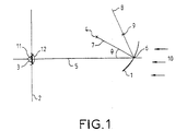
- the eye 3 of the user observes a spherical mirror 1.
- the pupillary plane 2 contains the pupil 11 of the eye, which is generally located 3 millimeters away from the cornea 12 of eye 3.
- the straight line 5 can correspond to the view of the user right in front of him, or to a view towards up, down, to one side or the opposite side.
- the spherical mirror 1 is placed in front of the user, its concavity is facing the user and the surface of this mirror is in the vicinity of its point of intersection 6 with the straight line 5.
- the spherical mirror 1 is supported by a sphere S whose center 4 does not belong to this line 5.
- the plane of figure 1 is a plane of the space which contains the center of the support sphere of the spherical mirror 1 and line 5 passing through the center of the pupil of the eye 3. This is the plane incidence of line 5 on the spherical mirror 1. Most often this plane coincides with the plane passing through the center of the pupil 11 and parallel in the theoretical plane of symmetry of the user's face.
- the radius 7 of the sphere S which passes through the point of intersection 6 is moved away from line 5 by an angle ⁇ .
- a non-zero value of this angle ⁇ characterizes off-axis use of the spherical mirror 1.
- the mirror spherical 1 itself is said to be "off axis”.
- an optical ray 8 which is symmetrical to the line 5 of the optical axis with respect to the described radius 7 of the sphere.
- an image 9 placed on this optical ray 8 at a distance equal to half the radius of curvature of the sphere is perceived by the eye 3 of the user as collimated to the first order because the light rays from image 9 thus placed are reflected by the spherical mirror 1 in eye direction 3 in the form of a beam of rays substantially parallel.
- Image 9 can be flat or have field curvature.
- the plane tangent to image 9 is preferably perpendicular to the radius optics 8.
- collimation by reflection on the spherical mirror is not not perfect, it is affected by spherical aberration, coma, astigmatism, field curvature and distortion but also optical offset aberration due to the spherical mirror 1 off axis.
- Various optical elements will be described in order to obtain from an image bright, provided by an imager, the perception by the eye of the user a good quality collimated image.
- the spherical mirror 1 may be semi-transparent. In this case light rays 10 coming from the environment outside the mirror spherical 1, that is to say coming to strike the convex face of this mirror, are transmitted to the eye 3 by the spherical mirror 1. This spherical mirror 1 realizes then a combiner which superimposes a collimated image with the direct view of the environment.
- the central field is defined as the beam of light rays from a particular point in image 9 which is the center of this image.
- the path of this department luminous is the optical axis of the device used.
- the optical axis is usually a broken line.
- Line 5 supports part of the axis optical. Most often, the image is presented straight in front of the user, the straight line 5 is then substantially normal to the user's face, but the image can for example be presented at the top of the field of vision of rest at infinity of the user and the line 5 is then oriented in the corresponding direction.
- FIG. 2 paths of light rays inside a embodiment of a device according to the invention are shown.
- the imager comprises by example a cathode ray tube or a liquid crystal screen.
- the screen can also be made for example by a fiber bundle section optics or a slide or the screen of a light intensifier tube.
- An image with any surface is displayed on the screen of the imager represented by its tangent plane 20.
- the plane 20 indifferently designates the screen of the imager or its tangent plane.
- the path of the light rays from the imager screen to the eye 3 of the user are traced for this embodiment of the invention. Eye 3 of the user is represented by his pupil who has the same reference for simplify the figures.
- the device comprises a spherical mirror 1 off axis and a mirror aspherical concave 21. It also includes a power lens 22 located between these two mirrors 1 and 21.
- the optical device comprises a lens diffractive 23 between the power lens 22 and the spherical mirror 1.
- the light rays coming from the screen 20 of the imager strike the concave asheric mirror 21.
- the light rays reflected by the aspheric concave mirror 21 pass through the power lens 22 and the diffractive lens 23 before hit the spherical mirror 1 off axis which collimates the image received by eye 3 of the user.
- the optical axis is supported by a straight line 31 which, on the Figure 2 is horizontal. This optical ray is reflected by the mirror spherical 1 in a second part 32 of the optical axis.
- the plane of incidence of the optical axis on the spherical mirror 1 is the plane containing the first and second parts 31 and 32 of the optical axis. It is the plane P of figure 2.
- first pupil image 24 which is the image of the pupil of the eye 3 given by the Sheric mirror 1 off axis.
- the normal 25 to the plane tangent to this first pupil image 24 does not have the same direction as section 32 of the corresponding optical axis.
- the first pupillary image 24 is tilted on the optical axis.
- the power lens 22 is preferably centered on this second part 32 of the optical axis.
- the power lens 22 is placed for example so that the first pupil image 24 is on the path of light rays between the sherry mirror 1 and the lens power 22.
- the assembly of the power lens 22 and the lens diffractive 23 forms a power group which corrects the residual image aberrations.
- the power group allows the optical device according to the invention to present good image quality. This power group is an optical element close to the first pupil image 24, it has very little effect on pupil image 24.
- the aspherical concave mirror is placed in the vicinity of the second part 32 of the optical axis, to be on the path of the rays which come from the pupil of the eye 1 - because the description is written here by going up the path real light rays from the imager screen- and reflect these rays towards the screen 20 of the imager.
- the useful part of the aspherical mirror 21 has a tangent plane whose the normal 28 is not parallel to the second part 32 of the optical axis.
- the aspherical mirror 21 is said to be inclined relative to this axis.
- the aspherical mirror 21 has a variable radius of curvature.
- the device according to the invention shown in Figure 2 is free of folding mirror, that is to say it is presented without any plane mirror.
- the flat mirrors do not modify the optical function, they do not bring not and do not correct aberration but they allow optical rays to bypass obstacles like the user's head. They are not necessary for the description of the invention.
- the plane P is the plane of Figure 2, it is also the plane of symmetry of the optics presented in this figure.
- the plane P of figure 2 is the plane incidence of the optical axis on the aspheric concave mirror 21.
- the intersection of the optical surface of the aspherical mirror 21 with this plane P is a plane curve that has a radius of curvature in each of its points. Moving along the curve, the value of the radius of curvature varied. The value of the radius of curvature is not constant and depending on the direction displacement, this value increases or decreases. It is said that the variation of radius of curvature along this curve is monotonous.
- An example having a simple mathematical expression of such a curve is part of a conical not degenerate.
- the conic is for example a parabola or a ellipse.
- the shape of the concave surface of the aspherical mirror 21 is such that the whole device ensures correction of aberrations on the image presented to the user due to the off-axis spherical mirror.
- the aspherical mirror 21 corrects the residual aberrations of the image pupil given by the spherical mirror 1 of the pupil of the eye 3, it is placed near the screen image 20 and therefore has little effect on this picture.
- the aspherical mirror 21 allows the optical device according to the invention to present a good quality of pupil.
- the aspherical mirror 21 does little on the quality of the image but it acts a lot on the quality of the pupil.
- a second order or quadric geometric surface describes the optical surface of the aspherical mirror 21.
- Such a surface has the advantage of being relatively easily modeled because it can be expressed in a suitable coordinate system in the form of a polynomial of the second degree.
- the geometric surface supporting the optical surface of the mirror aspherical 21 is for example a paraboloid or an ellipsoid.
- the geometric surface is preferably a surface of revolution. It then has the advantage of being fairly easy to manufacture. For the examples of paraboloid and ellipsoid, we can then speak of a mirror parabolic and ellipsoidal respectively.
- the axis of revolution is preferably in the plane P of FIG. 2 or plane of symmetry of the unfolded optics.
- the orientation of the axis of revolution is such that the aspherical mirror 21 compensates for the observed tilt of the image pupillary 24 that the spherical mirror 1 introduced into the optical device.
- the geometric surface is a paraboloid of revolution whose intersection with the plane of Figure 2 is a parabola 26.
- the axis of revolution coincides with axis 27 of the parabola 26.
- the axis of revolution is preferably directed according to the direction from the straight line 25 normal to the tangent plane of the first pupillary image 24 given by the spherical mirror 1 of the pupil of the eye 3 of the user.
- the axis 27 and the right 28 of the plane P of FIG. 2 which is normal to the center of the aspherical mirror 21 are not parallel; their directions are significantly different.
- the aspherical mirror 21 corresponds to a part off-center of a parabolic mirror because the useful surface of the paraboloid is not not in the immediate vicinity of the top of the parabola 26.
- the opening around the axis 28 is sufficient to optimize the draft left available to place for example deflection mirrors between the aspherical mirror 21 and lens 22.
- the angle of incidence of the optical axis on the aspherical mirror 21 also makes it possible to limit the useful surface and thus maintain good image quality over the entire surface.
- the angle incidence is preferably close to 45 degrees.
- the useful surface of the mirror 21 is for example estimated by a diameter of approximately 45 millimeters.
- an optical device comprises a relay optics 29 for moving the screen 20 away from the imager from the aspherical mirror 21. This distance is generally made necessary to satisfy space constraints. It allows for example for a viewfinder helmet to place the whole imager, which can be a ray tube cathodic, to a satisfactory position in the available volume of the helmet.
- a second pupillary image 30 can be observed on the part 33 of the optical axis, this image is located between the aspherical mirror 21 and the screen of the imager 20. This second pupil image 30 is seen by the aspherical mirror 21 through a group 35 of lenses belonging to relay optics 29.
- the paraboloid of revolution has two foci, one at infinity and the other at a finite distance from its summit.
- the aspherical mirror 21 is preferably placed so that the pupil images 24, 30 are perceived by the aspherical mirror 21, respectively through the group of power 22, 23 and the lenses 35, as located at its focal points; the first pupillary image 24 corresponding to the focus at infinity.
- the first image 24 of the pupil of the eye of the user given by the spherical mirror 1 is seen by the aspherical mirror 21 through the group of power 22, 23 combined.
- the pupillary image 24 is not entirely placed optically at infinity with respect to the parabolic mirror 21 because this would lead too large a dimension of the power lens 22.
- the embodiment described here by way of example corresponds to an optical distance sufficient between the aspherical mirror 21 and the first pupil image 24.
- the magnification between the two pupillary images 30 and 24 is preferably of a value close to one.
- Pupillary conjugation practically unitary has the advantage of reducing the size of the optical device, it minimizes the size of the optics while along the optical path. This reduction in size is advantageous for the weight of the device and for its cost.
- the pupillary image 30 has a tangent plane which is substantially normal to local optical axis 33: this is a correction made by the mirror aspheric 21. Indeed, the first image 24 of the pupil of the eye formed by the spherical mirror 1 is inclined relative to the local optical axis 32 and corresponds to the aberrations induced by this mirror 1; and the second image pupillary 30 is straightened relative to the optical axis 33 by the mirror Asherian 21.
- the surface of the aspherical mirror 21 is such that this mirror 21 straightens the pupil image with respect to the optical axis. This recovery allows compensate for the distortion introduced by the spherical mirror 1 off-axis. This rectification of the pupillary image corresponds to the correction of the aberration pupil spherical, it reduces the distortion of the image observed by the user of a device according to the invention.
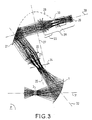
- FIG. 4 the optical diagram - unfolded - of a device according to the invention with relay optics is shown.
- This realization of the invention differs from that described with the aid of FIGS. 2 and 3 because the aspherical mirror 21 here has a geometric surface whose intersection with the plane P of symmetry of the unfolded optic, or plane of incidence of the axis optical, is supported by an ellipse 46.
- a power unit comprising at least one lens power 42 and a diffractive lens 43 is placed between the first image pupil 24 and the aspherical mirror 21.
- a relay optic 44 moves away the plane 20 tangent to the imager of the aspherical mirror 21.
- a second pupillary image 40 which is seen by the aspherical mirror 21 through a group of lenses 45.
- the surface of the mirror 21 is part of an ellipsoid. Most of the time this surface has a symmetry of revolution.
- the axis of revolution 47 is preferably located in the plane P of incidence of the optical axis.
- the axis of revolution of the ellipsoid merged with one of the axes principal of ellipse 46 defines an ellipsoidal mirror.
- the axis of revolution 47 is that the aspherical mirror 21 transforms the first pupil image 24 inclined to the optical axis 32 in a second pupil image 40 substantially perpendicular to the optical axis 41 on which it is located.
- the aspherical mirror 21 sees the first pupil image 24 by through power group 42, 43 and he sees the second image pupil 40 through the lens group 45.
- the ellipsoid of revolution presents two homes with a finite distance.
- the focal points of the ellipsoidal mirror 21 preferably correspond to the positions around which the pupillary images 24, 40 are seen by this mirror. We says that the pupillary images 24, 40 are conjugated by the mirror aspherical 21.
- the ellipsoidal mirror is completely stigmatic. He introduces the advantage of ensuring a good combination of surfaces placed in neighborhood of his homes. Its manufacture is more difficult than that of a mirror depending on the shape of a dish, it is therefore more expensive but a device according to the invention comprising an ellipsoidal mirror is generally more performance.
- the mirror 1 so far most often described as a spherical mirror may as well be a concave mirror with a shape close to the sphere which also induces distortion of the image seen by the user corresponding to an inclination of the pupil image relative to the axis optical.
- the invention makes it possible to correct the distortion due to a concave mirror. substantially spherical.
- the substantially spherical concave mirror 1 off-axis can be semi-transparent, in this case the light rays emitted by the landscape or the environment in the user's field of view are transmitted by this mirror and are received by the pupil of the eye simultaneously with the rays reflected by this same mirror and previously described.
- the semi-transparent mirror is a combiner. So it's a concave combiner substantially spherical used off axis.
- This combiner is preferably part of a protective visor eyes and even the user's face.
- a visor according to the invention has at least part reflective substantially spherical concave off axis.
- the visor In the use position the visor is folded down so that the part corresponding to the substantially spherical concave mirror 1 or placed in front of the user's eye.
- the entire presentation system of collimated images can be integrated into a helmet for example for a pilot of plane or helicopter and allows to realize a helmet sight.
- the device may only present substantially collimated images because in many practical cases it is sufficient to present focused images to several meters in front of the user.
- Second offset distortion species which corresponds to the pupillary spherical aberration induced by the reflection on the substantially spherical concave mirror 1 off axis, is shown in Figure 5, this distortion gives the impression of seeing the perspective grid.
- the images presented to the user and whose inherent distortion the substantially spherical concave visor off axis is corrected are particularly advantageous for a helmet visor because they respect the real dimensions of the objects represented.
- the correction of this distortion presents the advantage of allowing the user a good appreciation of the distances on the image he observes and allow him, for example, to pilot at night without positioning error.
Description
La présente invention concerne un dispositif optique de correction de l'image de la pupille de l'oeil donnée par un miroir concave sphérique. Plus précisément, un dispositif selon l'invention permet d'observer une image qui est corrigée de distorsion due à un miroir concave sphérique, ou sensiblement sphérique, incliné par rapport à la direction sous laquelle l'oeil observe ce miroir.The present invention relates to an optical device for correcting the image of the pupil of the eye given by a concave spherical mirror. More specifically, a device according to the invention makes it possible to observe an image which is corrected for distortion due to a spherical concave mirror, or substantially spherical, inclined relative to the direction in which the eye observe this mirror.
L'invention s'applique à un viseur de casque notamment, mais non exclusivement, pour pilote d'avion ou d'hélicoptères d'armes ou pour opérateur d'un simulateur d'entraínement.The invention applies to a helmet viewfinder in particular, but not exclusively, for pilot of aircraft or helicopter weapons or for operator of a training simulator.
Un viseur de casque est un dispositif de présentation d'images intégré à un casque. Le viseur permet au porteur du casque, comme par exemple un pilote d'avion en vol, d'observer des informations visuelles simultanément à la vue du paysage, ou du poste de pilotage, qu'il perçoit le plus souvent à travers une visière de protection.A helmet viewfinder is an image presentation device integrated into a helmet. The viewfinder allows the wearer of the helmet, as by example an airplane pilot in flight, observing visual information simultaneously with the view of the landscape, or of the cockpit, that he perceives the more often through a protective visor.
La présentation d'informations adaptées, par exemple sous forme de symboles, permet une aide au pilotage et à la navigation. Ainsi pour des véhicules armés la présentation d'un réticule réalise une aide à la visée d'une arme.The presentation of suitable information, for example in the form of symbols, allows assistance with piloting and navigation. So for armed vehicles the presentation of a reticle achieves an aiming aid of a weapon.
Les informations peuvent aussi consister en une image du paysage acquise par des capteurs différents de l'oeil du porteur du casque comme des capteurs infrarouge ou des intensificateurs de lumière visible pour compléter ou remplacer la vue directe.The information can also consist of a landscape image acquired by sensors different from the eye of the helmet wearer like infrared sensors or visible light intensifiers for complete or replace the direct view.
A l'intérieur du casque, un générateur d'image comporte un imageur comme par exemple un écran de tube cathodique ou un écran à cristaux liquides sur l'écran duquel une image est formée. Inside the helmet, an image generator includes an imager like for example a cathode ray tube screen or a crystal screen liquids on the screen of which an image is formed.
Le casque comporte le plus souvent une optique de relais pour transporter cette image jusqu'à un combineur qui assure une présentation de l'image transportée en superposition à la vue du paysage.The helmet most often includes a relay optic for transport this image to a combiner which provides a presentation of the image transported on top of the landscape view.
Pour une observation simultanée par le pilote du paysage qui est vu directement à l'infini, et de l'image de l'imageur, cette dernière est aussi focalisée à l'infini par une optique de collimation.For a simultaneous observation by the pilot of the landscape which is seen directly to infinity, and from the image of the imager, the latter is also focused to infinity by a collimation lens.
Lorsque le combineur est formé d'une simple lame plane semi-réfléchissante, la collimation de l'image peut être réalisée par une optique placée entre le combineur et l'imageur; une telle réalisation de l'art antérieur présente l'inconvénient principal de nécessiter une optique de collimation trop encombrante relativement au champ de vue restreint procuré.When the combiner is formed of a simple semi-reflective flat blade, collimation of the image can be achieved by an optical placed between the combiner and the imager; such an embodiment of the prior art has the main drawback of requiring collimation optics too cumbersome in relation to the restricted field of view provided.
Pour réduire l'encombrement, un combineur présentant une puissance optique a été proposé ; un tel combineur réalise pour son utilisateur à la fois la collimation de l'image et la superposition de l'image collimatée avec la vue du paysage.To reduce the space requirement, a combiner having a optical power has been proposed; such a combiner achieves for its user both image collimation and image overlay collimated with the view of the landscape.
L'art antérieur est riche de dispositifs nombreux et variés comportant un combineur à puissance optique. Tout d'abord un miroir sphérique concave réalise une collimation de qualité moyenne d'une image placée en un point particulier de l'espace situé sur l'axe du miroir et à une distance de celui-ci égale à la moitié de son rayon de courbure. En plaçant un imageur en ce point, l'oeil situé sur l'axe du miroir reçoit des rayons issus de l'imageur après leur réflexion sur le miroir sphérique, ces rayons sont parallèles et conduisent à la perception par l'oeil d'une image collimatée. Si de plus le miroir est semi-réfléchissant, il permet au même oeil d'observer le paysage par transparence. Cependant dans un tel dispositif l'imageur se trouve sur l'axe du miroir sphérique semi-transparent et il masque le champ de vue de l'utilisateur.The prior art is rich in numerous and varied devices comprising an optical power combiner. First a spherical mirror concave achieves a medium quality collimation of an image placed in a particular point in space located on the axis of the mirror and at a distance of this one equal to half of its radius of curvature. By placing an imager at this point, the eye located on the axis of the mirror receives rays from the imager after their reflection on the spherical mirror, these rays are parallel and lead to the perception by the eye of a collimated image. Yes more the mirror is semi-reflecting, it allows the same eye to observe the landscape by transparency. However in such a device the imager is found on the axis of the semi-transparent spherical mirror and it hides the field user view.
Pour dégager la vue de l'utilisateur, le miroir sphérique peut être incliné par rapport à la normale au visage et l'oeil de l'utilisateur n'est plus sur l'axe du miroir. Cette inclinaison présente l'inconvénient majeur de conduire à une image collimatée affectée d'aberrations optiques, d'excentrement en particulier, limitant trop fortement l'exploitation d'un tel dispositif.To clear the view of the user, the spherical mirror can be tilted relative to normal to the face and the user's eye is no longer on the axis of the mirror. This inclination has the major drawback of lead to a collimated image affected by optical aberrations, of eccentricity in particular, limiting too strongly the exploitation of such device.
Pour ne pas masquer le champ de vue de l'utilisateur tout en limitant les aberrations, l'art antérieur nous enseigne l'usage d'un miroir parabolique au lieu d'un miroir sphérique. L'imageur est placé au foyer du paraboloïde décrit par le miroir et l'oeil observe le miroir selon une parallèle à l'axe de révolution du paraboloïde.To not hide the user's field of view while limiting aberrations, the prior art teaches us the use of a parabolic mirror instead of a spherical mirror. The imager is placed at the focus of the paraboloid described by the mirror and the eye observes the mirror along a parallel to the axis of paraboloid revolution.
L'image collimatée perçue par l'oeil est dépourvue d'aberration sphérique mais reste principalement affectée d'une coma très pénalisante, dont l'importance augmente rapidement avec le champ. Ainsi l'imageur, tout en étant hors de l'axe du champ de vue, reste gênant dans le champ de vue.The collimated image perceived by the eye is devoid of aberration spherical but remains mainly affected by a very penalizing coma, whose importance increases rapidly with the field. So the imager, everything being outside the axis of the field of view, remains annoying in the field of view.
Un perfectionnement consiste à exploiter une double réflexion sur le miroir parabolique avec un miroir plan intermédiaire placé au niveau du front de l'utilisateur et appelé miroir de renvoi. Les deux réflexions se situent de par et d'autre de l'axe du paraboloïde, elles permettant d'obtenir une image collimatée affranchie de coma et dont les autres aberrations restent acceptables pour un champ de vue encore assez restreint.An improvement consists in exploiting a double reflection on the parabolic mirror with an intermediate plane mirror placed at the forehead of the user and called the return mirror. The two reflections are from by and from the axis of the paraboloid, they make it possible to obtain an image collimated freed from coma and whose other aberrations remain acceptable for a still fairly restricted field of view.
La volonté de réduire la gêne due au miroir de renvoi a conduit à une évolution de l'état de l'art. Un dispositif exploitant un miroir parabolique et une double réflexion présentant une asymétrie par rapport à l'axe de celui-ci a été décrit. S'il réduit la gêne dans le champ de vue, ce dispositif augmente les aberrations, en particulier l'astigmatisme. Le dispositif décrit comporte des lentilles inclinées pour réduire l'astigmatisme, il comporte également une lentille de champ pour compenser la courbure de champ et compense la distorsion par une déformation de l'image lors de sa génération : l'image est formée sur l'écran du tube cathodique de l'imageur avec une distorsion inverse de celle qu'elle est contrainte à subir en traversant le dispositif optique.The desire to reduce the discomfort caused by the deflection mirror has led to a evolution of the state of the art. A device using a parabolic mirror and a double reflection presenting an asymmetry with respect to the axis thereof has been described. If it reduces the discomfort in the field of view, this device increases aberrations, especially astigmatism. The device described comprises angled lenses to reduce astigmatism, it also features a field lens to compensate for the field curvature and compensates for the distortion by a distortion of the image during its generation: the image is formed on the imager cathode ray tube screen with distortion opposite to that which it is forced to undergo while crossing the device optical.
Par ailleurs l'idée initiale de collimation par un miroir sphérique a subi de nouveaux développements ; est ainsi décrit un dispositif avec miroir sphérique semi-transparent d'axe incliné, comprenant un prisme pour compenser les aberrations induites inévitables.Furthermore, the initial idea of collimation by a spherical mirror has undergone new developments; is thus described a device with mirror semi-transparent spherical inclined axis, comprising a prism for compensate for the inevitable induced aberrations.
Le prisme est placé sur le trajet des rayons lumineux entre l'imageur et le miroir sphérique. Les aberrations sont minimisées dans leur ensemble en adaptant l'inclinaison et l'ouverture du prisme. Et l'astigmatisme est corrigé par un élément optique supplémentaire qui doit être cylindrique.The prism is placed on the path of the light rays between the imager and the spherical mirror. Aberrations are minimized as a whole by adjusting the inclination and opening of the prism. And astigmatism is corrected by an additional optical element which must be cylindrical.
Ce dispositif est essentiellement pénalisé par un faible champ.This device is essentially penalized by a weak field.
Parallèlement des dispositifs à miroir sphérique sans inclinaison avec l'axe de vue et avec déport de l'imageur ont été réalisés.Parallel spherical mirror devices without tilting with the line of sight and with imager offset have been made.
Un tel dispositif comprend un miroir plan semi-réfléchissant placé entre le miroir sphérique et l'oeil de l'utilisateur, au niveau du foyer de collimation du miroir sphérique.Such a device comprises a semi-reflecting plane mirror placed between the spherical mirror and the user's eye, at the focal point of collimation of the spherical mirror.
De l'imageur à l'oeil de l'utilisateur, un rayon lumineux suit un trajet optique où, successivement, il frappe une première fois le miroir plan semi-réfléchissant, il est réfléchi sur celui-ci en direction du miroir sphérique, il est alors réfléchi sur ce dernier pour être renvoyé vers le miroir plan, il frappe une seconde fois le miroir plan et le traverse pour rejoindre l'oeil.From the imager to the eye of the user, a light ray follows a path optics where, successively, it strikes the semi-reflecting plane mirror for the first time, it is reflected on it towards the spherical mirror, it is then reflected on the latter to be returned to the plane mirror, it strikes a second time the plane mirror and crosses it to reach the eye.
L'ensemble des miroirs sphérique et plan est transparent pour les rayons émis par le paysage.The set of spherical and plane mirrors is transparent for rays emitted by the landscape.
Ce type de dispositif présente une image collimatée de bonne qualité.This type of device presents a good quality collimated image.
Cependant cette conception, impliquant un compromis entre la réflexion et la transmission par le miroir plan, présente l'inconvénient de ne transmettre à l'oeil qu'une faible partie de l'intensité lumineuse initiale et ainsi de limiter trop sévèrement les conditions d'utilisation d'un viseur de casque équipé de ce dispositif.However this conception, implying a compromise between the reflection and transmission by the plane mirror, has the disadvantage of not transmit to the eye only a small part of the initial light intensity and thus limiting the conditions of use of a viewfinder too severely helmet fitted with this device.
L'amélioration de la transmission à l'oeil de l'image utile est possible en inclinant légèrement la visière sphérique par rapport à l'axe de vue de l'utilisateur et en réalisant sur le miroir plan un traitement anti-réfléchissant sélectif en fonction de l'angle d'incidence des rayons lumineux.Improvement of the transmission to the eye of the useful image is possible by slightly tilting the spherical visor relative to the viewing axis of the user and by performing an anti-reflective treatment on the plane mirror selective according to the angle of incidence of the light rays.
Avec cette géométrie, les première et seconde incidences d'un même rayon lumineux sur le miroir plan présentent des valeurs angulaires distinctes qui permettent au traitement anti-réfléchissant sélectif, en s'affranchissant du compromis classique entre la réflexion et la transmission d'un rayon qui pénalise le dispositif précédent, de favoriser conjointement la réflexion du rayon initial et la transmission du rayon déjà réfléchi.With this geometry, the first and second incidences of the same light ray on the plane mirror have angular values which allow selective anti-reflective treatment, in particular overcoming the classic compromise between reflection and transmission a radius that penalizes the previous device, to jointly promote the reflection of the initial ray and the transmission of the ray already reflected.
Ce dispositif présente un champ de vue assez large mais il est affecté d'aberrations dues à l'inclinaison de l'axe du miroir sphérique. Certaines aberrations sont corrigées par une lentille de champ inclinée et par des lentilles sphériques.This device has a fairly wide field of view but it is affected aberrations due to the inclination of the axis of the spherical mirror. Some aberrations are corrected by an inclined field lens and by spherical lenses.
L'astigmatisme et la distorsion ne sont pas excessifs car l'inclinaison est faible mais ne sont pas corrigés optiquement. Seule une compensation de la distorsion par une déformation de l'image générée sur l'écran cathodique est envisagée.Astigmatism and distortion are not excessive because the tilt is weak but is not optically corrected. Only compensation distortion by a distortion of the image generated on the screen cathodic is envisaged.
Ce dispositif présente une luminosité améliorée, cependant la présence du miroir plan entre l'oeil et le miroir sphérique le plus souvent intégré à la visière du casque est un inconvénient majeur si ce n'est pour le confort, pour la sécurité de l'oeil d'une part et pour le coût élevé de son traitement anti-réfléchissant d'autre part.This device has an improved brightness, however the presence of the plane mirror between the eye and the spherical mirror most often integrated into the helmet visor is a major drawback if not for the comfort, for the safety of the eye on the one hand and for the high cost of its anti-reflective treatment on the other hand.
Le problème consiste à réaliser un dispositif de présentation d'images pour casque avec visière sphérique sans élément interposé entre l'oeil et la visière et présentant une image collimatée satisfaisante pour l'utilisateur c'est-à-dire dépourvue d'aberrations gênantes et présentant un grand champ de vue supérieur ou égal à 40 degrés.The problem is to make an image presentation device for helmet with spherical visor without element interposed between the eye and the visor and presenting a satisfactory collimated image for the user that is to say devoid of annoying aberrations and having a large field of view greater than or equal to 40 degrees.
L'utilisation d'une partie sphérique de la visière comme élément de collimation conduit à de fortes aberrations qu'il est nécessaire de corriger au moins partiellement.The use of a spherical part of the visor as an element of collimation leads to strong aberrations which it is necessary to correct at less partially.
C'est pourquoi l'invention propose un dispositif optique pour système de présentation d'images collimatées à un utilisateur comportant un imageur et un miroir concave sensiblement sphérique hors axe caractérisé en ce que le dispositif optique comporte un axe optique et un miroir concave asphérique incliné sur l'axe optique, l'intersection du miroir concave asphérique avec le plan d'incidence de l'axe optique étant une courbe à rayon de courbure variable, pour corriger la distorsion de l'image présentée à l'utilisateur, laquelle distorsion est due au miroir concave sensiblement sphérique hors axe.This is why the invention provides an optical device for system for presenting collimated images to a user comprising a imager and a substantially spherical concave mirror off-axis characterized in that the optical device comprises an optical axis and a concave mirror aspherical inclined on the optical axis, the intersection of the concave mirror aspherical with the plane of incidence of the optical axis being a curve at variable radius of curvature, to correct the distortion of the image presented to the user, which distortion is due to the concave mirror substantially spherical off axis.
Les rayons lumineux issus du centre de l'imageur forment le champ central de l'imageur. L'axe optique du dispositif correspond au trajet du rayon du champ central qui passe par le centre de la pupille de l'utilisateur.The light rays coming from the center of the imager form the field central of the imager. The optical axis of the device corresponds to the path of the radius of the central field which passes through the center of the user's pupil.
L'axe optique est le plus souvent une ligne brisée. Par exemple, si l'image est présentée à l'utilisateur droit devant lui, la partie de l'axe optique située entre l'oeil et le miroir sphérique est supportée par une première droite normale au centre de la pupille de l'utilisateur, l'axe optique présente une cassure au niveau de l'intersection de cette première droite avec le miroir sphérique, et l'image que le miroir sphérique donne de cette première droite supporte le segment suivant de l'axe optique.The optical axis is most often a broken line. For example, if the image is presented to the user straight ahead, the part of the optical axis located between the eye and the spherical mirror is supported by a first normal right at the center of the user's pupil, the optical axis presents a break at the intersection of this first straight line with the spherical mirror, and the image that the spherical mirror gives of this first right supports the next segment of the optical axis.
Le miroir concave asphérique placé entre le miroir sphérique et l'imageur est incliné par rapport à l'axe optique. La surface du miroir concave asphérique est de préférence une surface du second ordre ou quadratique.The aspherical concave mirror placed between the spherical mirror and the imager is tilted relative to the optical axis. The mirror surface aspheric concave is preferably a second order surface or quadratic.
Si l'invention est présentée sans miroir de pliage, il est toujours possible, après le positionnement théorique des divers éléments optiques de l'invention, d'ajouter un ou plusieurs miroirs plans qui n'apportent pas d'aberration mais permettent de satisfaire des contraintes d'encombrement par exemple pour que le dispositif soit adapté au contour de la tète de l'utilisateur. Une optique présentée sans miroir de pliage est appelée optique dépliée.If the invention is presented without a folding mirror, it is always possible, after the theoretical positioning of the various optical elements of the invention, to add one or more plane mirrors which do not provide aberration but allow to meet space constraints for example so that the device is adapted to the contour of the head of the user. An optic presented without a folding mirror is called unfolded optics.
Le plan de symétrie de l'optique dépliée contient la normale à la pupille de l'entrée de l'oeil de l'utilisateur et le centre du miroir sphérique.The plane of symmetry of the unfolded optics contains the normal to the pupil of the user's eye entrance and the center of the spherical mirror.
L'intersection de ce plan avec le miroir concave asphérique est une courbe plane à rayon de courbure variable comme une conique non dégénérée. La surface du miroir concave asphérique permet de corriger la distorsion de l'image présentée à l'utilisateur qui est due au miroir sphérique hors axe. The intersection of this plane with the aspheric concave mirror is a flat curve with variable radius of curvature like a conic not degenerate. The surface of the aspheric concave mirror corrects the distortion of the image presented to the user due to the spherical mirror off axis.
Dans une réalisation de l'invention, la surface optique du miroir concave asphérique incliné est supportée par un paraboloïde. Dans une autre réalisation, la surface concave asphérique s'appuie sur un ellipsoïde.In one embodiment of the invention, the optical surface of the mirror inclined aspheric concave is supported by a paraboloid. In another embodiment, the aspherical concave surface rests on an ellipsoid.
La surface du miroir concave asphérique est de préférence une partie d'une surface de révolution. Elle présente dans ce cas l'avantage d'une réalisation plus aisée.The surface of the aspherical concave mirror is preferably a part of a surface of revolution. In this case, it has the advantage of easier realization.
L'axe de révolution du miroir concave asphérique est situé dans le plan de symétrie de l'optique dépliée.The axis of revolution of the aspheric concave mirror is located in the plane of symmetry of the unfolded optics.
L'image de la pupille de l'oeil hors axe est la première image pupillaire du dispositif, elle est inclinée par rapport à l'axe optique. De cette première image pupillaire inclinée, le miroir asphérique selon l'invention donne une seconde image pupillaire redressée sur l'axe optique.The image of the pupil of the off-axis eye is the first image pupil of the device, it is inclined relative to the optical axis. Of this first inclined pupil image, the aspherical mirror according to the invention gives a second pupil image straightened on the optical axis.
Dans le cas d'un paraboloïde de révolution, l'axe de révolution du miroir concave asphérique est sensiblement parallèle à la normale à la première image pupillaire.In the case of a paraboloid of revolution, the axis of revolution of the aspheric concave mirror is substantially parallel to normal to the first pupil image.
Le dispositif comporte également une lentille de puissance sensiblement centrée et placée entre le miroir sphérique et le miroir concave asphérique.The device also includes a power lens substantially centered and placed between the spherical mirror and the concave mirror aspherical.
Lorsque la surface du miroir concave asphérique est décrite par un paraboloïde, la lentille de puissance conjugue l'image de la pupille de l'oeil de l'utilisateur, donnée par le miroir sphérique, au voisinage du foyer de conjugaison du paraboloïde.When the surface of the aspheric concave mirror is described by a paraboloid, the power lens combines the image of the pupil of the eye of the user, given by the spherical mirror, in the vicinity of the focus of conjugation of the paraboloid.
L'ellipsoïde présente l'avantage de posséder deux foyers à distance finie. Une telle surface est moins facile à usiner qu'un paraboloïde mais elle corrige mieux car le miroir ellipsoïdal est complètement stigmatique pour ses deux foyers et assure une bonne conjugaison des voisinages des foyers.The ellipsoid has the advantage of having two homes at a distance over. Such a surface is less easy to machine than a paraboloid, but it corrects better because the ellipsoidal mirror is completely stigmatic for its two homes and ensures a good combination of neighborhoods of homes.
L'invention présente l'avantage de corriger la distorsion de l'image présentée à l'oeil de l'utilisateur pour une pupille instrumentale large, par exemple d'au moins 15 millimètres de diamètre, et pour un champ large typiquement supérieur à 40 degrés. La pupille instrumentale est la zone de l'espace dans laquelle l'utilisateur de l'instrument doit placer la pupille de son oeil pour utiliser l'instrument.The invention has the advantage of correcting the image distortion presented to the eye of the user for a large instrumental pupil, by example of at least 15 millimeters in diameter, and for a wide field typically greater than 40 degrees. The instrumental pupil is the area of the space in which the user of the instrument must place the pupil of his eye to use the instrument.
Cette correction est particulièrement intéressante lorsqu'une. distorsion ne peut pas être imposée facilement au niveau de l'imageur. En effet l'art antérieur nous enseigne pour corriger la distorsion de l'image fournie par un ensemble optique d'introduire une distorsion inverse au niveau de l'imageur par correction électronique ; ceci est aisément réalisé lorsque l'imageur comporte un tube cathodique mais cette solution n'est pas adaptée à un imageur, comme par exemple un intensificateur de lumière, qui ne présente pas les réglages nécessaires de l'image.This correction is particularly interesting when one. distortion cannot be easily imposed at the imager. In effect the prior art teaches us to correct image distortion provided by an optical assembly to introduce reverse distortion to the imager level by electronic correction; this is easily achieved when the imager has a cathode ray tube but this solution is not suitable for an imager, such as a light intensifier, which does not have the necessary image adjustments.
L'invention peut être intégrée à un viseur de casque présentant une pupille instrumentale large et un champ large.The invention can be integrated into a helmet viewfinder having a wide instrumental pupil and a wide field.
D'autres caractéristiques et avantages de l'invention apparaítront à la lecture de la description détaillée suivante d'une réalisation particulière qui est faite en référence aux dessins annexés suivants dans lesquels les schémas optiques sont représentés dépliés c'est-à-dire sans miroir plan.
- la figure 1 représente schématiquement et partiellement un dispositif optique avec miroir combineur sphérique hors axe optique,
- la figure 2 représente un dispositif déplié selon l'invention,
- la figure 3 représente un dispositif selon l'invention avec un miroir parabolique et une optique de relais,
- la figure 4 représente un dispositif selon l'invention avec un miroir ellipsoïdal et une optique de relais,
- la figure 5 représente la distorsion que l'invention corrige.
- FIG. 1 schematically and partially represents an optical device with a spherical combiner mirror off the optical axis,
- FIG. 2 represents an unfolded device according to the invention,
- FIG. 3 represents a device according to the invention with a parabolic mirror and a relay optic,
- FIG. 4 represents a device according to the invention with an ellipsoidal mirror and a relay optic,
- FIG. 5 represents the distortion that the invention corrects.
Sur la figure 1, l'oeil 3 de l'utilisateur observe un miroir sphérique 1.
Dans la position d'observation, le plan pupillaire 2 contient la pupille 11 de
l'oeil, laquelle est généralement située à 3 millimètres en retrait de la cornée
12 de l'oeil 3.In FIG. 1, the
Une droite 5 passant par le centre de la pupille de l'oeil 3 et est, par
exemple, normale au plan pupillaire 2. On note qu'en fonction de son
orientation par rapport au visage de l'utilisateur, la droite 5 peut
correspondre à la vue de l'utilisateur droit devant lui, ou bien à une vue vers
le haut, vers le bas , vers un côté ou le côté opposé.A
Le miroir sphérique 1 est placé en avant de l'utilisateur, sa concavité
est tournée vers l'utilisateur et la surface de ce miroir est au voisinage de
son point d'intersection 6 avec la droite 5.The
Le miroir sphérique 1 est supporté par une sphère S dont le centre 4
n'appartient pas à cette droite 5. Le plan de la figure 1 est un plan de
l'espace qui contient le centre de la sphère support du miroir sphérique 1 et
la droite 5 passant par le centre de la pupille de l'oeil 3. C'est le plan
d'incidence de la droite 5 sur le miroir sphérique 1. Le plus souvent ce plan
est confondu avec le plan passant par le centre de la pupille 11 et parallèle
au plan de symétrie théorique du visage de l'utilisateur.The
Le rayon 7 de la sphère S qui passe par le point d'intersection 6 est
écarté de la droite 5 d'un angle . Une valeur non nulle de cet angle
caractérise une utilisation hors axe du miroir sphérique 1. Le miroir
sphérique 1 lui-même est dit "hors axe".The
On s'intéresse à un rayon optique 8 qui est symétrique de la droite 5
de l'axe optique par rapport au rayon 7 décrit de la sphère. En première
approximation, une image 9 placée sur ce rayon optique 8 à une distance
égale à la moitié du rayon de courbure de la sphère est perçue par l'oeil 3
de l'utilisateur comme collimatée au premier ordre car les rayons lumineux
issus de l'image 9 ainsi placée sont réfléchis par le miroir sphérique 1 en
direction de l'oeil 3 sous la forme d'un faisceau de rayons sensiblement
parallèles. L'image 9 peut être plane ou présenter de la courbure de champ.
Le plan tangent à l'image 9 est de préférence perpendiculaire au rayon
optique 8.We are interested in an
Cependant la collimation par réflexion sur le miroir sphérique n'est
pas parfaite, elle est affectée d'aberration sphérique, de coma,
d'astigmatisme, de courbure de champ et de distorsion mais aussi
d'aberration optique d'excentrement due au miroir sphérique 1 hors axe.
Divers éléments optiques vont être décrits afin d'obtenir à partir d'une image
lumineuse, fournie par un imageur, la perception par l'oeil de l'utilisateur
d'une image collimatée de bonne qualité.However collimation by reflection on the spherical mirror is not
not perfect, it is affected by spherical aberration, coma,
astigmatism, field curvature and distortion but also
optical offset aberration due to the
Le miroir sphérique 1 peut-être semi-transparent. Dans ce cas des
rayons lumineux 10 provenant de l'environnement extérieur au miroir
sphérique 1, c'est-à-dire venant frapper la face convexe de ce miroir, sont
transmis à l'oeil 3 par le miroir sphérique 1. Ce miroir sphérique 1 réalise
alors un combineur qui superpose une image collimatée avec la vue directe
de l'environnement.The
Le champ central est défini comme le faisceau des rayons lumineux
issus d'un point particulier de l'image 9 qui est le centre de cette image. On
considère un rayon lumineux particulier qui appartient au champ central et
qui passe par le centre de la pupille de l'utilisateur. Le trajet de ce rayon
lumineux est l'axe optique du dispositif utilisé. L'axe optique est
généralement une ligne brisée. La droite 5 supporte une partie de l'axe
optique. Le plus souvent, l'image est présentée droit devant l'utilisateur, la
droite 5 est alors sensiblement normale au visage de l'utilisateur, mais
l'image peut être par exemple présentée en haut du champ de vision de
repos à l'infini de l'utilisateur et la droite 5 est alors orientée dans la
direction correspondante.The central field is defined as the beam of light rays
from a particular point in image 9 which is the center of this image. We
consider a particular light ray which belongs to the central field and
which passes through the center of the user's pupil. The path of this department
luminous is the optical axis of the device used. The optical axis is
usually a broken line.
Sur la figure 2, des trajets de rayons lumineux à l'intérieur d'une réalisation d'un dispositif selon l'invention sont représentés.In FIG. 2, paths of light rays inside a embodiment of a device according to the invention are shown.
Dans cette réalisation, l'imageur, non représenté, comporte par
exemple un tube cathodique ou un écran à cristaux liquides. L'écran peut
aussi être réalisé par exemple par une section de faisceau de fibres
optiques ou une diapositive ou l'écran d'un tube intensificateur de lumière.
Une image dont la surface est quelconque est affichée sur l'écran de
l'imageur représenté par son plan tangent 20. Par exemple si l'image est
plane, elle est contenue dans le plan tangent 20. Par la suite, pour simplifier,
le plan 20 désigne indifféremment l'écran de l'imageur ou son plan tangent.
Le trajet des rayons lumineux de l'écran de l'imageur jusqu'à l'oeil 3 de
l'utilisateur sont tracés pour cette réalisation de l'invention. L'oeil 3 de
l'utilisateur est représenté par sa pupille qui porte la même référence pour
simplifier les figures.In this embodiment, the imager, not shown, comprises by
example a cathode ray tube or a liquid crystal screen. The screen can
also be made for example by a fiber bundle section
optics or a slide or the screen of a light intensifier tube.
An image with any surface is displayed on the screen of
the imager represented by its
Le dispositif comprend un miroir sphérique 1 hors axe et un miroir
concave asphérique 21. Il comprend également une lentille de puissance 22
située entre ces deux miroirs 1 et 21.The device comprises a
Dans cette réalisation, le dispositif optique comporte une lentille
diffractive 23 entre la lentille de puissance 22 et le miroir sphérique 1.In this embodiment, the optical device comprises a
Les rayons lumineux issus de l'écran 20 de l'imageur frappent le
miroir concave ashérique 21.The light rays coming from the
Les rayons lumineux réfléchis par le miroir concave asphérique 21
traversent la lentille de puissance 22 et la lentille diffractive 23 avant de
frapper le miroir sphérique 1 hors axe qui assure une collimation de l'image
reçue par l'oeil 3 de l'utilisateur.The light rays reflected by the aspheric
On observe maintenant le trajet des rayons lumineux dans l'autre
sens c'est-à-dire en partant de l'oeil 3 de l'utilisateur et en remontant les
différents éléments optiques vers l'écran de l'afficheur. Les rayons sont
réfléchis par le miroir sphérique 1 hors axe, le rayon particulier qu'est l'axe
optique est aussi réfléchi sur le miroir sphérique 1.We now observe the path of the light rays in the other
meaning that is to say starting from the
Dans une première partie 31 entre le centre de la pupille de l'oeil 3 et
le miroir sphérique 1, l'axe optique est supporté par une droite 31 qui, sur la
figure 2, est horizontale. Ce rayon optique est réfléchi par le miroir
sphérique 1 en une seconde partie 32 de l'axe optique.In a
Le plan d'incidence de l'axe optique sur le miroir sphérique 1 est le
plan contenant les première et seconde parties 31 et 32 de l'axe optique.
C'est le plan P de la figure 2.The plane of incidence of the optical axis on the
Sur la seconde partie 32 de l'axe optique on observe une première
image pupillaire 24 qui est l'image de la pupille de l'oeil 3 donnée par le
miroir shérique 1 hors axe. La normale 25 au plan tangent à cette première
image pupillaire 24 ne présente pas la même direction que la section 32 de
l'axe optique correspondante. La première image pupillaire 24 est inclinée
sur l'axe optique. On the
La lentille de puissance 22 est de préférence centrée sur cette
seconde partie 32 de l'axe optique. La lentille de puissance 22 est placée
par exemple de façon à ce que la première image pupillaire 24 soit sur le
trajet des rayons lumineux entre le miroir shérique 1 et la lentille de
puissance 22. L'ensemble de la lentille de puissance 22 et de la lentille
diffractive 23 forme un groupe de puissance qui permet de corriger les
aberrations résiduelles de l'image. Le groupe de puissance permet au
dispositif optique selon l'invention de présenter une bonne qualité d'image.
Ce groupe de puissance est un élément optique proche de la première
image pupillaire 24, il affecte très peu l'image pupillaire 24.The
Le miroir concave asphérique est placé au voisinage de la seconde
partie 32 de l'axe optique, pour être sur le trajet des rayons qui viennent de
la pupille de l'oeil 1 - car la description est ici écrite en remontant le trajet
réél des rayons lumineux issus de l'écran de l'imageur- et réfléchir ces
rayons vers l'écran 20 de l'imageur.The aspherical concave mirror is placed in the vicinity of the
La partie utile du miroir asphérique 21 présente un plan tangent dont
la normale 28 n'est pas parallèle à la seconde partie 32 de l'axe optique. Le
miroir asphérique 21 est dit incliné par rapport à cet axe.The useful part of the
Dans le plan P d'incidence de l'axe optique sur le miroir sphérique 1
qui est défini par les deux premières parties de l'axe optique 31 et 32, le
miroir asphérique 21 présente un rayon de courbure variable.In the plane P of incidence of the optical axis on the
Le dispositif selon l'invention représenté sur la figure 2 est exempt de miroir de pliage, c'est-à-dire qu'il est présenté sans aucun miroir plan. En effet les miroirs plans ne modifient pas la fonction optique, ils n'apportent pas et ne corrigent pas d'aberration mais ils permettent aux rayons optiques de contourner des obstacles comme la tête de l'utilisateur. Ils ne sont pas nécessaires à la description de l'invention.The device according to the invention shown in Figure 2 is free of folding mirror, that is to say it is presented without any plane mirror. In indeed the flat mirrors do not modify the optical function, they do not bring not and do not correct aberration but they allow optical rays to bypass obstacles like the user's head. They are not necessary for the description of the invention.
Le plan P est le plan de la figure 2, c'est aussi le plan de symétrie de
l'optique présentée sur cette figure. Le plan P de la figure 2 est le plan
d'incidence de l'axe optique sur le miroir concave asphérique 21.
L'intersection de la surface optique du miroir asphérique 21 avec ce plan P
est une courbe plane qui présente un rayon de courbure en chacun de ses
points. En se déplaçant le long de la courbe, la valeur du rayon de courbure
varie. La valeur du rayon de courbure n'est pas constante et selon le sens
de déplacement, cette valeur croít ou bien décroít. On dit que la variation du
rayon de courbure le long de cette courbe est monotone. Une exemple ayant
une expression mathématique simple d'une telle courbe est une partie d'une
conique non dégénérée. La conique est par exemple une parabole ou une
ellipse.The plane P is the plane of Figure 2, it is also the plane of symmetry of
the optics presented in this figure. The plane P of figure 2 is the plane
incidence of the optical axis on the aspheric
La forme de la surface concave du miroir asphérique 21 est telle que
l'ensemble du dispositif assure une correction des aberrations sur l'image
présentée à l'utilisateur qui sont dues au miroir sphérique hors axe.The shape of the concave surface of the
Le miroir asphérique 21 corrige les aberrations résiduelles de l'image
pupillaire donnée par le miroir sphérique 1 de la pupille de l'oeil 3, il est
placé à proximité de l'image de l'écran 20 et n'affecte donc que peu cette
image. Le miroir asphérique 21 permet au dispositif optique selon l'invention
de présenter une bonne qualité de pupille. Le miroir asphérique 21 agit peu
sur la qualité de l'image mais il agit beaucoup sur la qualité de la pupille.The
Une surface géométrique du second ordre ou quadrique décrit la
surface optique du miroir asphérique 21. Une telle surface présente
l'avantage d'être relativement facilement modélisée car elle peut s'exprimer
dans un repère adéquat sous la forme d'un polynôme du second degré.A second order or quadric geometric surface describes the
optical surface of the
La surface géométrique supportant la surface optique du miroir asphérique 21 est par exemple un paraboloïde ou un ellipsoïde.The geometric surface supporting the optical surface of the mirror aspherical 21 is for example a paraboloid or an ellipsoid.
La surface géométrique est de préférence une surface de révolution. Elle présente alors l'avantage d'être assez facile à fabriquer. Pour les exemples de paraboloïde et d'ellipsoïde, on peut alors parler de miroir respectivement parabolique et ellipsoïdal.The geometric surface is preferably a surface of revolution. It then has the advantage of being fairly easy to manufacture. For the examples of paraboloid and ellipsoid, we can then speak of a mirror parabolic and ellipsoidal respectively.
L'axe de révolution est de préférence dans le plan P de la figure 2 ou
plan de symétrie de l'optique dépliée. L'orientation de l'axe de révolution est
telle que le miroir asphérique 21 compense l'inclinaison observée de l'image
pupillaire 24 que le miroir sphérique 1 introduit dans le dispositif optique. The axis of revolution is preferably in the plane P of FIG. 2 or
plane of symmetry of the unfolded optics. The orientation of the axis of revolution is
such that the
Dans la réalisation de la figure 2, la surface géométrique est un
paraboloïde de révolution dont l'intersection avec le plan de la figure 2 est
une parabole 26. L'axe de révolution est confondu avec l'axe 27 de la
parabole 26. L'axe de révolution est de'préférence dirigé selon la direction
de la droite 25 normale au plan tangent de la première image pupillaire 24
donnée par le miroir sphérique 1 de la pupille de l'oeil 3 de l'utilisateur.In the embodiment of FIG. 2, the geometric surface is a
paraboloid of revolution whose intersection with the plane of Figure 2 is
a
L'axe 27 et la droite 28 du plan P de la figure 2 qui est normale au
centre du miroir asphérique 21 ne sont pas parallèles; leurs orientations sont
sensiblement différentes. Le miroir asphérique 21 correspond à une partie
décentrée d'un miroir parabolique car la surface utile du paraboloïde n'est
pas au voisinage immédiat du sommet de la parabole 26.The
L'ouverture autour de l'axe 28 est suffisante pour optimiser le tirage
laissé disponible pour placer par exemple des miroirs de renvoi entre le
miroir asphérique 21 et la lentille 22. Et l'angle d'incidence de l'axe optique
sur le miroir asphérique 21 permet aussi de limiter la surface utile et ainsi de
conserver une bonne qualité d'image sur toute la surface. L'angle
d'incidence est de préférence voisin de 45 degrés. Dans cette réalisation, la
surface utile du miroir 21 est par exemple estimée par un diamètre d'environ
45 millimètres.The opening around the
Sur la figure 3, un dispositif optique selon l'invention comporte une
optique relais 29 pour éloigner l'écran 20 de l'imageur du miroir asphérique
21. Cet éloignement est généralement rendu nécessaire pour satisfaire des
contraintes d'encombrement. Il permet par exemple pour un viseur de
casque de placer l'ensemble de l'imageur, qui peut être un tube à rayons
cathodiques, à une position satisfaisante dans le volume disponible du
casque.In FIG. 3, an optical device according to the invention comprises a
Sur la figure 3, on voit la troisième partie 33 de l'axe optique qui
correspond à la réflexion de la seconde partie 32 de ce même axe optique
sur le miroir asphérique 21. L'optique de relais 29 est placée entre le miroir
concave asphérique 21 et l'écran 20 de l'imageur, elle est sensiblement
alignée avec la troisième partie 33 de l'axe optique. Cette optique de relais
essentiellement centrée est simple à réaliser.In Figure 3, we see the
Une seconde image pupillaire 30 peut être observée sur la partie 33
de l'axe optique, cette image est située entre le miroir asphérique 21 et
l'écran de l'imageur 20. Cette seconde image pupiliaire 30 est vue par le
miroir asphérique 21 à travers un groupe 35 de lentilles appartenant à
l'optique de relais 29.A second
Le paraboloïde de révolution possède deux foyers, l'un à l'infini et
l'autre à une distance finie de son sommet. Le miroir asphérique 21 est
placé de préférence de façon à ce que les images pupillaires 24, 30 soient
perçues par le miroir asphérique 21, à travers respectivement le groupe de
puissance 22, 23 et les lentilles 35, comme situées au niveau de ses foyers;
la première image pupillaire 24 correspondant au foyer à l'infini. On dit que
la première image 24 de la pupille de l'oeil de l'utilisateur donnée par le
miroir sphérique 1 est vue par le miroir asphérique 21 à travers le groupe de
puissance 22, 23 de façon conjuguée.The paraboloid of revolution has two foci, one at infinity and
the other at a finite distance from its summit. The
Plus précisément, l'image pupillaire 24 n'est pas tout à fait placée
optiquement à l'infini par rapport au miroir parabolique 21 car cela conduirait
à une dimension trop importante de la lentille de puissance 22. La
réalisation ici décrite à titre d'exemple correspond à un éloignement optique
suffisant entre le miroir asphérique 21 et la première image pupillaire 24.More specifically, the
D'autre part, le grandissement entre les deux images pupillaires 30 et
24 est de préférence d'une valeur proche de un. La conjugaison pupillaire
pratiquement unitaire présente l'avantage de réduire l'encombrement du
dispositif optique, elle permet une minimisation de la taille des optiques tout
au long du chemin optique. Cette réduction d'encombrement est
avantageuse pour le poids du dispositif et pour son coût.On the other hand, the magnification between the two
L'image pupillaire 30 présente un plan tangent qui est sensiblement
normal à l'axe optique 33 local: c'est une correction apportée par le miroir
asphérique 21. En effet, la première image 24 de la pupille de l'oeil formée
par le miroir sphérique 1 est inclinée par rapport à l'axe optique local 32 et
correspond aux aberrations induites par ce miroir 1; et la seconde image
pupillaire 30 est redressée par rapport à l'axe optique 33 par le miroir
ashérique 21.The
La surface du miroir asphérique 21 est telle que ce miroir 21 redresse
l'image pupillaire par rapport à l'axe optique. Ce redressement permet de
compenser la distorsion introduite par le miroir shérique 1 hors axe. Ce
redressement de l'image pupillaire correspond à la correction de l'aberration
sphérique pupillaire, il réduit la distorsion de l'image observée par
l'utilisateur d'un dispositif selon l'invention.The surface of the
Sur la figure 4, le schéma optique - déplié - d'un dispositif selon
l'invention avec une optique de relais est représenté. Cette réalisation de
l'invention se distingue de celle décrite à l'aide des figures 2 et 3 car le
miroir asphérique 21 présente ici une surface géométrique dont l'intersection
avec le plan P de symétrie de l'optique dépliée, ou plan d'incidence de l'axe
optique, est supportée par une ellipse 46.In FIG. 4, the optical diagram - unfolded - of a device according to
the invention with relay optics is shown. This realization of
the invention differs from that described with the aid of FIGS. 2 and 3 because the
Un groupe de puissance comportant au moins une lentille de
puissance 42 et une lentille diffractive 43 est placé entre la première image
pupillaire 24 et le miroir asphérique 21. Dans cette réalisation, comme dans
celle représentée sur la figure précédente, une optique de relais 44 éloigne
le plan 20 tangent à l'imageur du miroir asphérique 21. On observe une
seconde image pupillaire 40 qui est vue par le miroir asphérique 21 à travers
un groupe de lentilles 45.A power unit comprising at least one
La surface du miroir 21 est une partie d'un ellipsoïde. Le plus souvent
cette surface présente une symétrie de révolution. L'axe de révolution 47 est
de préférence situé dans le plan P d'incidence de l'axe optique.The surface of the
L'axe de révolution de l'ellipsoïde confondu avec un des axes
principaux de l'ellipse 46 définit un miroir ellipsoïdal.The axis of revolution of the ellipsoid merged with one of the axes
principal of
L'axe de révolution 47 est que le miroir asphérique 21 transforme la
première image pupillaire 24 inclinée sur l'axe optique 32 en une seconde
image pupillaire 40 sensiblement perpendiculaire à l'axe optique 41 sur
laquelle elle est située. The axis of
Le miroir asphérique 21 voit la première image pupillaire 24 par
l'intermédiaire du groupe de puissance 42, 43 et il voit la seconde image
pupillaire 40 à travers le groupe de lentilles 45.The
L'ellipsoïde de révolution présente deux foyers à distance finie. Les
foyers du miroir ellipsoïdal 21 correspondent de préférence aux positions
autour desquelles sont vues les images pupillaires 24, 40 par ce miroir. On
dit que les images pupillaires 24, 40 sont conjuguées par le miroir
asphérique 21.The ellipsoid of revolution presents two homes with a finite distance. The
focal points of the
Le miroir ellipsoïdal est complètement stigmatique. Il présente l'avantage d'assurer une bonne conjugaison de surfaces placées au voisinage de ses foyers. Sa fabrication est plus difficile que celle d'un miroir suivant la forme d'un paraboloïde, il est donc plus coûteux mais un dispositif selon l'invention comportant un miroir ellipsoïdal est globalement plus performant.The ellipsoidal mirror is completely stigmatic. He introduces the advantage of ensuring a good combination of surfaces placed in neighborhood of his homes. Its manufacture is more difficult than that of a mirror depending on the shape of a dish, it is therefore more expensive but a device according to the invention comprising an ellipsoidal mirror is generally more performance.
Le miroir 1 jusqu'ici le plus souvent décrit comme un miroir sphérique
peut aussi bien être un miroir concave de forme proche de la sphère qui
induit également une distorsion de l'image vue par l'utilisateur
correspondant à une inclinaison de l'image pupillaire par rapport à l'axe
optique. L'invention permet de corriger la distorsion due à un miroir concave
sensiblement sphérique.The
Le miroir concave sensiblement sphérique 1 hors axe peut être semi-transparent,
dans ce cas les rayons lumineux émis par le paysage ou
l'environnement dans le champ de vue de l'utilisateur sont transmis par ce
miroir et sont reçus par la pupille de l'oeil simultanément avec les rayons
réfléchis par ce même miroir et précédemment décrits. Le miroir semi-transparent
est un combineur. C'est donc un combineur concave
sensiblement sphérique utilisé hors axe.The substantially spherical
Ce combineur fait de préférence partie d'une visière de protection des yeux et même du visage de l'utilisateur.This combiner is preferably part of a protective visor eyes and even the user's face.
Une visière selon l'invention présente au moins une partie réfléchissante sensiblement sphérique concave hors axe. A visor according to the invention has at least part reflective substantially spherical concave off axis.
En position d'utilisation la visière est rabattue de façon à ce que la
partie correspondant au miroir concave sensiblement sphérique 1 soit
placée devant l'oeil de l'utilisateur. L'ensemble du dispositif de présentation
d'images collimatées peut être intégré à un casque par exemple pour un
pilote d'avion ou d'hélicoptère et permet de réaliser un viseur de casque. Le
dispositif peut ne présenter que des images sensiblement collimatées car
dans de nombreux cas pratique il suffit de présenter des images focalisées à
plusieurs mètres devant l'utilisateur.In the use position the visor is folded down so that the
part corresponding to the substantially spherical
La distorsion d'une image présentant un quadrillage conduit à la
déformation du quadrillage. La distorsion d'excentrement de seconde
espèce qui correspond à l'aberration sphérique pupillaire induite par la
réflexion sur le miroir concave sensiblement sphérique 1 hors axe, est
représentée sur la figure 5, cette distorsion donne l'impression de voir le
quadrillage en perspective.The distortion of an image presenting a grid leads to the
deformation of the grid. Second offset distortion
species which corresponds to the pupillary spherical aberration induced by the
reflection on the substantially spherical
Les images présentées à l'utilisateur et dont la distorsion inhérente à la visière concave sensiblement sphérique hors axe est corrigée sont particulièrement avantageuses pour un viseur de casque car elles respectent les dimensions réelles des objets représentés. Ce qui est utile lorsque le viseur présente une image superposée à la vue directe et l'est encore plus lorsque l'image présentée se substitue pour l'utilisateur à la vue directe par exemple en cas de mauvaise visibilité ou en cas de simulation précise de l'environnement. La correction de cette distorsion présente l'avantage de permettre à l'utilisateur une bonne appréciation des distances sur l'image qu'il observe et de lui permettre par exemple de piloter de nuit sans erreur de positionnement.The images presented to the user and whose inherent distortion the substantially spherical concave visor off axis is corrected are particularly advantageous for a helmet visor because they respect the real dimensions of the objects represented. What is useful when the viewfinder presents an image superimposed on the direct view and is even more when the image presented replaces the user with the view direct for example in case of poor visibility or in the event of simulation precise of the environment. The correction of this distortion presents the advantage of allowing the user a good appreciation of the distances on the image he observes and allow him, for example, to pilot at night without positioning error.
Claims (13)
- Optical device for a system for presenting collimated images through the pupil of a user's eye (3), comprising an imager (20) and an off-axis substantially spherical concave mirror (1), characterized in that since the user's eye (3) is in a position predetermined by the use of the device, the axis (31) which passes through the centre of the user's pupil and which is normal to the latter makes a non-zero angle of incidence with the substantially spherical concave mirror (1), the said axis being a first part (31) of the optical axis (31, 32, 33) passing through the optical device, the optical device comprising an aspherical concave mirror (21) inclined on a second part of the optical axis (32) corresponding to the reflection of the first part (31) of the optical axis oil the substantially spherical concave mirror (1), the intersection of the aspherical concave mirror (21) with the plane of incidence of the optical axis being a curve with a variable radius of curvature, in order to correct the distortion of the image presented to the user, which distortion is due to the off-axis substantially spherical concave mirror (1).
- Device according to Claim 1, characterized in that along this curve, the variation in the radius of curvature is monotonic.
- Device according to Claim 2, characterized in that the curve is a parabola or an ellipse.
- Device according to one of Claims 1 to 3, characterized in that the optical surface of the aspherical mirror (21) is supported by a paraboloid.
- Device according to Claim 4, characterized in that the optical surface of the aspherical mirror is supported by an axisymmetric paraboloid.
- Device according to one of Claims 1 to 3, characterized in that the optical surface of the aspherical mirror (21) is supported by an ellipsoid.
- Device according to Claim 6, characterized in that the optical surface of the aspherical mirror (21) is supported by an axisymmetric ellipsoid.
- Device according to Claim 5, characterized in that the axisymmetric axis of the axisymmetric surface is substantially parallel to the normal (25) to the plane tangential to the first pupillary image (24) that the off-axis substantially spherical concave mirror (1) gives of the pupil of the user's eye (3).
- Device according to one of Claims 5, 7 and 8, characterized in that the device comprises a power group (22, 23) placed between the substantially spherical (1) and aspherical (21) mirrors and in that the image of the pupil of the user's eye given by the substantially spherical mirror (1) is seen by the aspherical concave mirror (21) through the power group (22, 23) in a conjugate manner.
- Device according to one of Claims 5, 8 and 9, characterized in that the surface of the aspherical mirror (21) is part of a paraboloid and in that the aspherical mirror (21) sees the first pupillary image (24) that the substantially spherical concave mirror (1) forms of the pupil of the user, substantially at infinity.
- Device according to one of Claims 7, 8 and 9, characterized in that when the surface of the aspherical mirror (21) is supported on an ellipsoid, the aspherical mirror (21) sees, in the vicinity of one of its focuses, the first pupillary image (24) that the substantially spherical concave mirror (1) forms of the user's pupil.
- Device according to one of the preceding claims, characterized in that the substantially spherical mirror (1) is semi-transparent.
- Device according to one of the preceding claims, characterized in that the system for presenting collimated images is a helmet visor.
Applications Claiming Priority (3)
| Application Number | Priority Date | Filing Date | Title |
|---|---|---|---|
| FR9709893 | 1997-08-01 | ||
| FR9709893A FR2766931B1 (en) | 1997-08-01 | 1997-08-01 | OPTICAL DEVICE FOR A HELMET SIGHT COMPRISING AN ASPHERIC MIRROR |
| PCT/FR1998/001673 WO1999006867A1 (en) | 1997-08-01 | 1998-07-28 | Optical device for helmet visor comprising aspheric mirror |
Publications (3)
| Publication Number | Publication Date |
|---|---|
| EP1000375A1 EP1000375A1 (en) | 2000-05-17 |
| EP1000375B1 true EP1000375B1 (en) | 2002-04-03 |
| EP1000375B2 EP1000375B2 (en) | 2007-06-27 |
Family
ID=9509945
Family Applications (1)
| Application Number | Title | Priority Date | Filing Date |
|---|---|---|---|
| EP98941474A Expired - Lifetime EP1000375B2 (en) | 1997-08-01 | 1998-07-28 | Optical device for helmet visor comprising aspheric mirror |
Country Status (6)
| Country | Link |
|---|---|
| US (1) | US6504658B1 (en) |
| EP (1) | EP1000375B2 (en) |
| AU (1) | AU8983798A (en) |
| DE (1) | DE69804625T3 (en) |
| FR (1) | FR2766931B1 (en) |
| WO (1) | WO1999006867A1 (en) |
Families Citing this family (13)
| Publication number | Priority date | Publication date | Assignee | Title |
|---|---|---|---|---|
| US6957551B2 (en) * | 2000-08-18 | 2005-10-25 | Linde Ag | Method for producing an air separation installation |
| FR2813128B1 (en) | 2000-08-18 | 2003-01-17 | Thomson Csf | LIQUID CRYSTAL DISPLAY DEVICE WITH BIREFRINGENCE COMPENSATOR |
| US7550698B2 (en) * | 2003-07-10 | 2009-06-23 | Lightswitch Safety Systems, Inc. | Light sensor arrangement for auto-darkening lenses and method |
| US8403502B2 (en) * | 2008-11-18 | 2013-03-26 | Barco N.V. | Collimated visual display with elliptical front projection screen |
| US10359545B2 (en) | 2010-10-21 | 2019-07-23 | Lockheed Martin Corporation | Fresnel lens with reduced draft facet visibility |
| US9632315B2 (en) | 2010-10-21 | 2017-04-25 | Lockheed Martin Corporation | Head-mounted display apparatus employing one or more fresnel lenses |
| FR2999302B1 (en) * | 2012-12-10 | 2017-12-22 | Yahiatene Daniel Ait | DEVICE FOR ENHANCING THE VISION OF A HUMAN BEING |
| WO2016061447A1 (en) | 2014-10-17 | 2016-04-21 | Lockheed Martin Corporation | Head-wearable ultra-wide field of view display device |
| US9939650B2 (en) | 2015-03-02 | 2018-04-10 | Lockheed Martin Corporation | Wearable display system |
| US10754156B2 (en) | 2015-10-20 | 2020-08-25 | Lockheed Martin Corporation | Multiple-eye, single-display, ultrawide-field-of-view optical see-through augmented reality system |
| US9995936B1 (en) | 2016-04-29 | 2018-06-12 | Lockheed Martin Corporation | Augmented reality systems having a virtual image overlaying an infrared portion of a live scene |
| JP6348953B2 (en) * | 2016-11-25 | 2018-06-27 | ロッキード マーティン コーポレーション | Method and system for generating a free space reflective optical surface |
| JPWO2021070970A1 (en) * | 2019-10-12 | 2021-04-15 |
Citations (9)
| Publication number | Priority date | Publication date | Assignee | Title |
|---|---|---|---|---|
| CH131850A (en) * | 1927-04-16 | 1929-03-15 | C P Goerz Optische Anstalt Akt | Panoramic device. |
| DE3513672A1 (en) * | 1984-04-17 | 1985-12-19 | Recon Optical, Inc., Barrington, Ill. | PANORAMIC OBSERVATION SYSTEM |
| DE3717906A1 (en) * | 1987-05-27 | 1988-12-08 | Zeiss Carl Fa | WIDE-ANGLE WATCHING WINDOW |
| FR2692369A1 (en) * | 1992-06-12 | 1993-12-17 | Thomson Csf | Omnidirectional monitoring device with optimal coverage of the surrounding space by joining fields. |
| FR2692368A1 (en) * | 1992-06-12 | 1993-12-17 | Thomson Csf | Wide range infrared panoramic watch device with high angular coverage, especially on site. |
| US5485306A (en) * | 1992-11-13 | 1996-01-16 | Hughes Aircraft Company | Wide field of view multi-telescope optical multiplexed sensor |
| DE19535969A1 (en) * | 1994-09-30 | 1996-04-04 | Republic Lens Co Inc | Multiple imaging lens system |
| US5598263A (en) * | 1994-09-13 | 1997-01-28 | Matra Marconi Space France | Light-backscatter measurement device suitable for use on board a craft |
| GB2305573A (en) * | 1995-09-22 | 1997-04-09 | Thomson Csf | High-speed optronic panoramic surveillance system |
Family Cites Families (15)
| Publication number | Priority date | Publication date | Assignee | Title |
|---|---|---|---|---|
| US4084887A (en) * | 1976-05-07 | 1978-04-18 | Kms Fusion, Inc. | All-reflective optical target illumination system with high numerical aperture |
| US5880888A (en) * | 1989-01-23 | 1999-03-09 | Hughes Aircraft Company | Helmet mounted display system |
| IL99420A (en) * | 1991-09-05 | 2000-12-06 | Elbit Systems Ltd | Helmet mounted display |
| US5293271A (en) * | 1992-04-15 | 1994-03-08 | Virtual Reality, Inc. | Retrocollimator optical system |
| FR2696013B1 (en) | 1992-09-21 | 1994-11-25 | Sextant Avionique | Retractable holographic combiner, especially for aircraft. |
| FR2698767B1 (en) | 1992-12-08 | 1995-01-06 | Sextant Avionique | System for holding at least one visor on helmet. |
| FR2700023B1 (en) | 1992-12-24 | 1995-02-10 | Sextant Avionique | Holding and guiding device for collimator. |
| FR2717272B1 (en) | 1994-03-08 | 1996-05-31 | Sextant Avionique | Mechanical attachment device for a display system on a helmet. |
| FR2717045B1 (en) | 1994-03-11 | 1996-05-31 | Sextant Avionique | Head equipment with isostatic connection between hull and optronic equipment. |
| FR2725114B1 (en) | 1994-09-30 | 1996-11-15 | Sextant Avionique | QUICK MOUNT MODULAR HELMET |
| JPH0943536A (en) * | 1995-05-25 | 1997-02-14 | Canon Inc | Image display device |
| JPH09219832A (en) | 1996-02-13 | 1997-08-19 | Olympus Optical Co Ltd | Image display |
| FR2769721B1 (en) * | 1997-10-10 | 2001-01-26 | Sextant Avionique | OPTICAL DEVICE FOR A HELMET SIGHT COMPRISING A MANGIN MIRROR |
| FR2772242B1 (en) | 1997-12-12 | 2000-03-03 | Sextant Avionique | HELMET COMPRISING A WIDTHABLE PART BY AN INFLATABLE CUSHION |
| FR2772343B1 (en) | 1997-12-12 | 2000-03-03 | Sextant Avionique | ATTACHMENT OF ON-BOARD EQUIPMENT SUPPORT |
-
1997
- 1997-08-01 FR FR9709893A patent/FR2766931B1/en not_active Expired - Fee Related
-
1998
- 1998-07-28 US US09/463,405 patent/US6504658B1/en not_active Expired - Fee Related
- 1998-07-28 EP EP98941474A patent/EP1000375B2/en not_active Expired - Lifetime
- 1998-07-28 AU AU89837/98A patent/AU8983798A/en not_active Abandoned
- 1998-07-28 DE DE69804625T patent/DE69804625T3/en not_active Expired - Lifetime
- 1998-07-28 WO PCT/FR1998/001673 patent/WO1999006867A1/en active IP Right Grant
Patent Citations (9)
| Publication number | Priority date | Publication date | Assignee | Title |
|---|---|---|---|---|
| CH131850A (en) * | 1927-04-16 | 1929-03-15 | C P Goerz Optische Anstalt Akt | Panoramic device. |
| DE3513672A1 (en) * | 1984-04-17 | 1985-12-19 | Recon Optical, Inc., Barrington, Ill. | PANORAMIC OBSERVATION SYSTEM |
| DE3717906A1 (en) * | 1987-05-27 | 1988-12-08 | Zeiss Carl Fa | WIDE-ANGLE WATCHING WINDOW |
| FR2692369A1 (en) * | 1992-06-12 | 1993-12-17 | Thomson Csf | Omnidirectional monitoring device with optimal coverage of the surrounding space by joining fields. |
| FR2692368A1 (en) * | 1992-06-12 | 1993-12-17 | Thomson Csf | Wide range infrared panoramic watch device with high angular coverage, especially on site. |
| US5485306A (en) * | 1992-11-13 | 1996-01-16 | Hughes Aircraft Company | Wide field of view multi-telescope optical multiplexed sensor |
| US5598263A (en) * | 1994-09-13 | 1997-01-28 | Matra Marconi Space France | Light-backscatter measurement device suitable for use on board a craft |
| DE19535969A1 (en) * | 1994-09-30 | 1996-04-04 | Republic Lens Co Inc | Multiple imaging lens system |
| GB2305573A (en) * | 1995-09-22 | 1997-04-09 | Thomson Csf | High-speed optronic panoramic surveillance system |
Also Published As
| Publication number | Publication date |
|---|---|
| DE69804625T2 (en) | 2002-10-17 |
| DE69804625T3 (en) | 2007-12-06 |
| FR2766931A1 (en) | 1999-02-05 |
| FR2766931B1 (en) | 1999-10-15 |
| US6504658B1 (en) | 2003-01-07 |
| EP1000375B2 (en) | 2007-06-27 |
| EP1000375A1 (en) | 2000-05-17 |
| WO1999006867A1 (en) | 1999-02-11 |
| AU8983798A (en) | 1999-02-22 |
| DE69804625D1 (en) | 2002-05-08 |
Similar Documents
| Publication | Publication Date | Title |
|---|---|---|
| EP1019775B1 (en) | Optical device for helmet visor comprising a mangin mirror | |
| WO2000020913A1 (en) | Optical device for helmet visor comprising a diffractive mirror | |
| CA2001086C (en) | Optical sighting system, mainly for visual display helmet | |
| EP1000375B1 (en) | Optical device for helmet visor comprising aspheric mirror | |
| EP0011024A1 (en) | Helmet mounted visualization system | |
| FR2526553A1 (en) | DISPLAY DEVICE FOR HIGH HEAD STEERING COLLIMATOR | |
| FR2638242A1 (en) | Optical collimation system, especially for a helmet display | |
| EP3215884B1 (en) | Head-mounted display with crossed optics | |
| EP1714179A2 (en) | Method and device for generating retinal images using the stigmatism of the two foci of a substantially elliptical sight | |
| FR2559593A1 (en) | HIGH HEAD TYPE DRIVING COLLIMATOR | |
| FR2996650A1 (en) | HIGH HEAD DISPLAY FOR MOTOR VEHICLE | |
| EP1057069B1 (en) | Optical device for pilot's visor comprising a tubular mirror | |
| EP1258771B1 (en) | Space saving optical architecture for wide field of view helmet visor | |
| FR2818393A1 (en) | Head up display visor manufacturing procedure includes regulation of combiner's angle of inclination and compensation for resulting abberations | |
| BE1011163A5 (en) | Night vision systems a light intensification. | |
| FR2472762A1 (en) | BINOCULAR DAY VISION DEVICE | |
| TW202409678A (en) | Optical device and method | |
| WO2013068688A2 (en) | Portable augmented vision device | |
| FR3115894A1 (en) | IMAGE PROJECTION APPARATUS AND ASSOCIATED CONTROL UNIT | |
| WO2002031574A1 (en) | Individual visual display system | |
| FR2712994A1 (en) | Helmet with visual display directed onto partially reflecting visor | |
| FR2922322A1 (en) | OPTICAL DEVICE FOR NIGHT VISION WITH STANDARD LIGHT INTENSIFIER | |
| FR2702283A1 (en) | Oscillating mirror bezel for infrared vision. | |
| WO2011030033A2 (en) | Retina projection device | |
| FR3015701A1 (en) | RETINAL PROJECTION DEVICE. |
Legal Events
| Date | Code | Title | Description |
|---|---|---|---|
| PUAI | Public reference made under article 153(3) epc to a published international application that has entered the european phase |
Free format text: ORIGINAL CODE: 0009012 |
|
| 17P | Request for examination filed |
Effective date: 20000105 |
|
| AK | Designated contracting states |
Kind code of ref document: A1 Designated state(s): DE FR GB |
|
| 17Q | First examination report despatched |
Effective date: 20001127 |
|
| RAP1 | Party data changed (applicant data changed or rights of an application transferred) |
Owner name: THALES AVIONICS S.A. |
|
| GRAG | Despatch of communication of intention to grant |
Free format text: ORIGINAL CODE: EPIDOS AGRA |
|
| GRAG | Despatch of communication of intention to grant |
Free format text: ORIGINAL CODE: EPIDOS AGRA |
|
| GRAG | Despatch of communication of intention to grant |
Free format text: ORIGINAL CODE: EPIDOS AGRA |
|
| GRAH | Despatch of communication of intention to grant a patent |
Free format text: ORIGINAL CODE: EPIDOS IGRA |
|
| GRAH | Despatch of communication of intention to grant a patent |
Free format text: ORIGINAL CODE: EPIDOS IGRA |
|
| REG | Reference to a national code |
Ref country code: GB Ref legal event code: IF02 |
|
| GRAA | (expected) grant |
Free format text: ORIGINAL CODE: 0009210 |
|
| AK | Designated contracting states |
Kind code of ref document: B1 Designated state(s): DE FR GB |
|
| REF | Corresponds to: |
Ref document number: 69804625 Country of ref document: DE Date of ref document: 20020508 |
|
| GBT | Gb: translation of ep patent filed (gb section 77(6)(a)/1977) |
Effective date: 20020701 |
|
| PLBQ | Unpublished change to opponent data |
Free format text: ORIGINAL CODE: EPIDOS OPPO |
|
| PLBI | Opposition filed |
Free format text: ORIGINAL CODE: 0009260 |
|
| PLBF | Reply of patent proprietor to notice(s) of opposition |
Free format text: ORIGINAL CODE: EPIDOS OBSO |
|
| 26 | Opposition filed |
Opponent name: ELBIT SYSTEMS LTD. Effective date: 20021230 |
|
| PLBF | Reply of patent proprietor to notice(s) of opposition |
Free format text: ORIGINAL CODE: EPIDOS OBSO |
|
| PLBF | Reply of patent proprietor to notice(s) of opposition |
Free format text: ORIGINAL CODE: EPIDOS OBSO |
|
| RDAF | Communication despatched that patent is revoked |
Free format text: ORIGINAL CODE: EPIDOSNREV1 |
|
| APBP | Date of receipt of notice of appeal recorded |
Free format text: ORIGINAL CODE: EPIDOSNNOA2O |
|
| APBQ | Date of receipt of statement of grounds of appeal recorded |
Free format text: ORIGINAL CODE: EPIDOSNNOA3O |
|
| APAH | Appeal reference modified |
Free format text: ORIGINAL CODE: EPIDOSCREFNO |
|
| APBU | Appeal procedure closed |
Free format text: ORIGINAL CODE: EPIDOSNNOA9O |
|
| PUAH | Patent maintained in amended form |
Free format text: ORIGINAL CODE: 0009272 |
|
| STAA | Information on the status of an ep patent application or granted ep patent |
Free format text: STATUS: PATENT MAINTAINED AS AMENDED |
|
| 27A | Patent maintained in amended form |
Effective date: 20070627 |
|
| AK | Designated contracting states |
Kind code of ref document: B2 Designated state(s): DE FR GB |
|
| GBTA | Gb: translation of amended ep patent filed (gb section 77(6)(b)/1977) | ||
| PGFP | Annual fee paid to national office [announced via postgrant information from national office to epo] |
Ref country code: DE Payment date: 20110720 Year of fee payment: 14 Ref country code: GB Payment date: 20110727 Year of fee payment: 14 |
|
| GBPC | Gb: european patent ceased through non-payment of renewal fee |
Effective date: 20120728 |
|
| PG25 | Lapsed in a contracting state [announced via postgrant information from national office to epo] |
Ref country code: GB Free format text: LAPSE BECAUSE OF NON-PAYMENT OF DUE FEES Effective date: 20120728 Ref country code: DE Free format text: LAPSE BECAUSE OF NON-PAYMENT OF DUE FEES Effective date: 20130201 |
|
| REG | Reference to a national code |
Ref country code: DE Ref legal event code: R119 Ref document number: 69804625 Country of ref document: DE Effective date: 20130201 |
|
| REG | Reference to a national code |
Ref country code: FR Ref legal event code: PLFP Year of fee payment: 19 |
|
| REG | Reference to a national code |
Ref country code: FR Ref legal event code: PLFP Year of fee payment: 20 |
|
| PGFP | Annual fee paid to national office [announced via postgrant information from national office to epo] |
Ref country code: FR Payment date: 20170628 Year of fee payment: 20 |