EP0999613A1 - Electrical connector for circuit board comprising plug and receptacle - Google Patents
Electrical connector for circuit board comprising plug and receptacle Download PDFInfo
- Publication number
- EP0999613A1 EP0999613A1 EP99402711A EP99402711A EP0999613A1 EP 0999613 A1 EP0999613 A1 EP 0999613A1 EP 99402711 A EP99402711 A EP 99402711A EP 99402711 A EP99402711 A EP 99402711A EP 0999613 A1 EP0999613 A1 EP 0999613A1
- Authority
- EP
- European Patent Office
- Prior art keywords
- plug
- base
- contacts
- edge
- card
- Prior art date
- Legal status (The legal status is an assumption and is not a legal conclusion. Google has not performed a legal analysis and makes no representation as to the accuracy of the status listed.)
- Granted
Links
Images

Classifications
-
- H—ELECTRICITY
- H01—ELECTRIC ELEMENTS
- H01R—ELECTRICALLY-CONDUCTIVE CONNECTIONS; STRUCTURAL ASSOCIATIONS OF A PLURALITY OF MUTUALLY-INSULATED ELECTRICAL CONNECTING ELEMENTS; COUPLING DEVICES; CURRENT COLLECTORS
- H01R12/00—Structural associations of a plurality of mutually-insulated electrical connecting elements, specially adapted for printed circuits, e.g. printed circuit boards [PCB], flat or ribbon cables, or like generally planar structures, e.g. terminal strips, terminal blocks; Coupling devices specially adapted for printed circuits, flat or ribbon cables, or like generally planar structures; Terminals specially adapted for contact with, or insertion into, printed circuits, flat or ribbon cables, or like generally planar structures
- H01R12/70—Coupling devices
- H01R12/71—Coupling devices for rigid printing circuits or like structures
- H01R12/72—Coupling devices for rigid printing circuits or like structures coupling with the edge of the rigid printed circuits or like structures
- H01R12/721—Coupling devices for rigid printing circuits or like structures coupling with the edge of the rigid printed circuits or like structures cooperating directly with the edge of the rigid printed circuits
-
- H—ELECTRICITY
- H01—ELECTRIC ELEMENTS
- H01R—ELECTRICALLY-CONDUCTIVE CONNECTIONS; STRUCTURAL ASSOCIATIONS OF A PLURALITY OF MUTUALLY-INSULATED ELECTRICAL CONNECTING ELEMENTS; COUPLING DEVICES; CURRENT COLLECTORS
- H01R13/00—Details of coupling devices of the kinds covered by groups H01R12/70 or H01R24/00 - H01R33/00
- H01R13/02—Contact members
- H01R13/26—Pin or blade contacts for sliding co-operation on one side only
-
- H—ELECTRICITY
- H01—ELECTRIC ELEMENTS
- H01R—ELECTRICALLY-CONDUCTIVE CONNECTIONS; STRUCTURAL ASSOCIATIONS OF A PLURALITY OF MUTUALLY-INSULATED ELECTRICAL CONNECTING ELEMENTS; COUPLING DEVICES; CURRENT COLLECTORS
- H01R2201/00—Connectors or connections adapted for particular applications
- H01R2201/16—Connectors or connections adapted for particular applications for telephony
Definitions
- the present invention relates to a socket connection intended to come and engage on the edge of a printed circuit board with contacts intended to take elastic support on the part and on the other side of the card to establish a direct connection with conductive connection pads of this menu.
- the invention relates in particular to a socket connection of an accessory to be connected directly to the circuit board of a mobile phone, this phone mobile not having on its connector base input / output but a printed circuit (usually soldered to the input / output connector) directly accessible for connection to an external accessory or sheet.
- the major technical problem posed with this type application relates to the degradation, or even the destruction of contacts by sharp edges abrasives of the printed circuit at the time of insertion, which has the effect of considerably limiting the number of connection / disconnection operations.
- a second problem is to ensure a pressure of sufficient contact between the accessory contacts and the connection areas of the printed circuit.
- the object of the invention is precisely to solve the two problems above.
- the plug contacts do not rub on the outer edges of the map, when the engagement of the plug in the socket.
- the friction on the connection pads is very limited.
- the contacts are supported elastically on the connection areas of the card only when the plug is almost completely engaged on the edge of the card, without degradation of contacts when inserting the plug into the socket.
- the base and the plug comprise means complementary to lock them together at the end of stroke for inserting the plug into the socket.
- the means for move the plug up include ramps rising inside the base and making protruding above a plane passing through the edge bottom of the plug insertion opening, these ramps cooperating with the end of the plug for the move up.
- the means for making bend down the flexible part of the plug include at least one descending ramp located inside the base and protruding below of a plane passing through the upper edge of the opening inserting the plug, this ramp cooperating with the end of said flexible part to make it flex down.
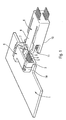
- connection socket intended to come to engage on the edge 2 of a printed circuit board 1, has contacts 3, 4 intended to bear elastically on either side of card 1 to establish a direct connection with conductive pads of connection 5 of this card.
- the socket comprises a base 6 without contacts intended to be fixed on the printed circuit board 1 by lugs hook 19 (fittings).
- This base 6 includes a opening 7 to receive a card 8 comprising two parallel rows of elastic contacts 3, 4 intended to be supported on the conductive pads 5, after insertion of plug 8 into opening 7 of base 6.
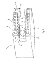
- one 3 rows of contacts is carried by a first flexible part 9 of the plug 8 which can engage in the opening 7 of the base 6.
- the other row of contacts 4 is carried by a second part 10 of sheet 8 separated from the first part 9 by a recess 11 and can engage under edge 2 of the circuit board printed 1.
- the base 6 and the plug 8 include additional resources for lock together at the end of the insertion stroke of plug 8 in socket 6.
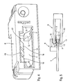
- the means to move plug 8 upwards when insertion into base 6 include two ramps risers 12 located inside the base 6 and protruding above a plane passing through the edge lower 13 of the opening 7 for inserting the plug 8 in the base 6. These ramps 12 cooperate with the end 14a of two guide beams 14 arranged on either side of the flexible part 9 of the sheet 8 to move it up.
- Figure 4 also shows that the ramps 12 are located at a certain distance d from the edge lower 13 of the opening 7 for inserting the plug 8 in base 6.
- the two ramps 12 are each located near a side edge 15 of the opening 7 for introducing sheet 8.
- Means for bending down the flexible part 9 of the plug 8 during its insertion in the base 6 include two descending ramps 16 (see Figure 4) located inside the base 6 and protruding below a plane passing through the edge upper 17 of the opening 7 for inserting the plug 8. These ramps 16 cooperate with the end 9a of the flexible part 9 of the plug to bend it towards the bottom.
- Additional means to lock together the base 6 and the plug 8 include a spout latching 18 (see Figures 2 and 3) formed on the upper face and near the end 9a of the part flexible 9 of the plug 8 cooperating with a lamella flexible 19 (see FIG. 4) formed in the base 6.
- connection socket that we have just described works as follows:
- the lower row 4 of contacts rests elastically on the ranges of connection 5 provided on the underside of the card.
- the spout 18 located at the front of the flexible part 9 of the plug 8 snaps onto the end of the strip 19 located inside the base 6, thus locking the plug 8 of the base 6.
Abstract
Description
La présente invention concerne une prise de connexion destinée à venir s'engager sur le bord d'une carte de circuit imprimé et comportant des contacts destinés à prendre appui élastiquement de part et d'autre de la carte pour établir une connexion, directe avec des plages conductrices de connexion de cette carte.The present invention relates to a socket connection intended to come and engage on the edge of a printed circuit board with contacts intended to take elastic support on the part and on the other side of the card to establish a direct connection with conductive connection pads of this menu.
L'invention concerne en particulier une prise de connexion d'un accessoire à connecter directement au circuit imprimé d'un téléphone mobile, ce téléphone mobile ne possédant pas sur son embase de connecteur d'entrée/sortie mais un circuit imprimé (habituellement soudé au connecteur d'entrée/sortie) directement accessible pour sa connexion à un accessoire extérieur ou fiche.The invention relates in particular to a socket connection of an accessory to be connected directly to the circuit board of a mobile phone, this phone mobile not having on its connector base input / output but a printed circuit (usually soldered to the input / output connector) directly accessible for connection to an external accessory or sheet.
L'art antérieur le plus proche est le EP 0 263746.The closest prior art is EP 0 263746.
Le problème technique majeur posé avec ce type d'application est relatif à la dégradation, voire la destruction des contacts par les arêtes fortement abrasives du circuit imprimé au moment de l'insertion, ce qui a pour effet de limiter considérablement le nombre de manoeuvres de connexion/déconnexion.The major technical problem posed with this type application relates to the degradation, or even the destruction of contacts by sharp edges abrasives of the printed circuit at the time of insertion, which has the effect of considerably limiting the number of connection / disconnection operations.
Un second problème est d'assurer une pression de contact suffisante entre les contacts de l'accessoire et les plages de connexion du circuit imprimé.A second problem is to ensure a pressure of sufficient contact between the accessory contacts and the connection areas of the printed circuit.
Le but de l'invention est précisément de résoudre les deux problèmes ci-dessus.The object of the invention is precisely to solve the two problems above.
Suivant l'invention, la prise de connexion est caractérisée en ce qu'elle comprend une embase dépourvue de contacts destinée à être fixée sur le bord de la carte de circuit imprimé, cette embase comportant une ouverture pour recevoir une fiche comportant deux rangées parallèles de contacts élastiques destinés à prendre appui sur lesdites plages conductrices, après insertion de la fiche dans l'ouverture de l'embase, l'une des rangées de contacts étant portée par une première partie flexible de la fiche pouvant s'engager dans l'ouverture de l'embase, l'autre rangée de contacts étant portée par une seconde partie de la fiche séparée de la première partie par un évidement et pouvant s'engager sous le bord de la carte de circuit imprimé, l'intérieur de l'embase et la fiche comportant des moyens coopérant ensemble lors de l'insertion de la fiche dans l'embase pour :
- guider l'introduction de la fiche dans l'embase, sans que les rangées de contacts ne touchent les bords de la carte et les plages de connexion ;
- déplacer la fiche vers le haut pour permettre un accostage de la rangée de contacts portée par la seconde partie de la fiche sur les plages conductrices situées sous le bord de la carte et simultanément ;
- faire fléchir vers le bas la première partie flexible de la fiche, pour permettre un accostage de la rangée de contacts portée par cette partie flexible sur les plages conductrices situées sur le bord de la carte.
- guide the insertion of the plug into the base, without the rows of contacts touching the edges of the card and the connection pads;
- move the plug upwards to allow the row of contacts carried by the second part of the plug to approach the conductive pads located under the edge of the card and simultaneously;
- bending down the first flexible part of the plug, to allow docking of the row of contacts carried by this flexible part on the conductive pads located on the edge of the card.
Ainsi, les contacts de la fiche ne frottent pas sur les arêtes extérieures de la carte, lors de l'engagement de la fiche dans l'embase. De plus, le frottement sur les plages de connexion est très limité.Thus, the plug contacts do not rub on the outer edges of the map, when the engagement of the plug in the socket. In addition, the friction on the connection pads is very limited.
En effet, les contacts prennent appui élastiquement sur les plages de connexion de la carte seulement lorsque la prise est presque complètement engagée sur le bord de la carte, sans dégradation des contacts à l'insertion de la fiche dans l'embase.Indeed, the contacts are supported elastically on the connection areas of the card only when the plug is almost completely engaged on the edge of the card, without degradation of contacts when inserting the plug into the socket.
On limite ainsi considérablement l'usure des plages de connexion de la carte.This considerably limits the wear of the card connection areas.
De plus, il existe un auto-nettoyage des contacts après la première phase d'insertion lorsque ces derniers frottent sur les plages du circuit imprimé sur une courte distance pour l'engagement complet.In addition, there is a self-cleaning of contacts after the first phase of insertion when these last rub on the tracks of the printed circuit on a short distance for full engagement.
Selon une version préférée de l'invention, l'embase et la fiche comportent des moyens complémentaires pour les verrouiller ensemble en fin de course d'introduction de la fiche dans l'embase.According to a preferred version of the invention, the base and the plug comprise means complementary to lock them together at the end of stroke for inserting the plug into the socket.
De préférence également, les moyens pour déplacer la fiche vers le haut comprennent des rampes montantes situées à l'intérieur de l'embase et faisant saillie au-dessus d'un plan passant par le bord inférieur de l'ouverture d'introduction de la fiche, ces rampes coopérant avec l'extrémité de la fiche pour la déplacer vers le haut.Preferably also, the means for move the plug up include ramps rising inside the base and making protruding above a plane passing through the edge bottom of the plug insertion opening, these ramps cooperating with the end of the plug for the move up.
De préférence également, les moyens pour faire fléchir vers le bas la partie flexible de la fiche, comprennent au moins une rampe descendante située à l'intérieur de l'embase et faisant saillie au-dessous d'un plan passant par le bord supérieur de l'ouverture d'introduction de la fiche, cette rampe coopérant avec l'extrémité de ladite partie flexible pour la faire fléchir vers le bas.Preferably also, the means for making bend down the flexible part of the plug, include at least one descending ramp located inside the base and protruding below of a plane passing through the upper edge of the opening inserting the plug, this ramp cooperating with the end of said flexible part to make it flex down.
D'autres particularités et avantages de l'invention apparaítront encore dans la description ci-après.Other features and advantages of the invention will appear further in the description below.
Aux dessins annexés donnés à titre d'exemples non limitatifs :
- la figure 1 est une vue en perspective de l'embase fixée sur une carte de circuit imprimé et de la fiche d'une prise de connexion conforme à l'invention ;
- la figure 2 est une vue en perspective à échelle agrandie de la fiche ;
- la
fiche 3 est une autre vue en perspective de la fiche ; - la figure 4 est une vue en perspective de l'embase ;
- la figure 5 est une vue en coupe longitudinale de la fiche partiellement engagée dans l'embase.
- Figure 1 is a perspective view of the base fixed to a printed circuit board and the plug of a connection socket according to the invention;
- Figure 2 is an enlarged perspective view of the plug;
-
sheet 3 is another perspective view of the sheet; - Figure 4 is a perspective view of the base;
- Figure 5 is a longitudinal sectional view of the plug partially engaged in the base.
Dans la réalisation représentée sur les figures
1 à 4, la prise de connexion destinée à venir s'engager
sur le bord 2 d'une carte de circuit imprimé 1, comporte
des contacts 3, 4 destinés à prendre appui élastiquement
de part et d'autre de la carte 1 pour établir une
connexion directe avec des plages conductrices de
connexion 5 de cette carte.In the embodiment shown in the figures
1 to 4, the connection socket intended to come to engage
on the
Conformément à l'invention, la prise comprend
une embase 6 dépourvue de contacts destinée à être fixée
sur la carte de circuit imprimé 1 par des pattes
d'accrochage 19 (fittings). Cette embase 6 comporte une
ouverture 7 pour recevoir une fiche 8 comportant deux
rangées parallèles de contacts élastiques 3, 4 destinés
à prendre appui sur les plages conductrices 5, après
insertion de la fiche 8 dans l'ouverture 7 de l'embase
6.According to the invention, the socket comprises
a
Comme indiqué sur les figures 2 et 3, l'une 3
des rangées de contacts est portée par une première
partie flexible 9 de la fiche 8 pouvant s'engager dans
l'ouverture 7 de l'embase 6. L'autre rangée de contacts
4 est portée par une seconde partie 10 de la fiche 8
séparée de la première partie 9 par un évidement 11 et
pouvant s'engager sous le bord 2 de la carte de circuit
imprimé 1.As shown in Figures 2 and 3, one 3
rows of contacts is carried by a first
L'intérieur de l'embase 6 et la fiche 8 comportent des moyens coopérant ensemble lors de l'insertion de la fiche 8 dans l'embase 6 pour :
- guider l'introduction de la
fiche 8 dans l'embase 6 sans que les rangées decontacts - déplacer la
fiche 8 vers le haut pour permettre un accostage de la rangée decontacts 4 portée par laseconde partie 10 de lafiche 8 sur les plages conductrices 5 situées sous lebord 2 de la carte 1 et simultanément ; - faire fléchir vers le bas la première partie
flexible 9 de la
fiche 8 pour permettre un accostage de la rangée decontacts 3 portée par cette partie flexible 9 sur les plages conductrices 5 situées sur lebord 2 de la carte 1.
- guide the introduction of the
plug 8 into thebase 6 without the rows ofcontacts - move the
plug 8 upward to allow docking of the row ofcontacts 4 carried by thesecond part 10 of theplug 8 on the conductive pads 5 located under theedge 2 of the card 1 and simultaneously; - flex the first
flexible part 9 of theplug 8 downward to allow contacting of the row ofcontacts 3 carried by thisflexible part 9 on the conductive pads 5 located on theedge 2 of the card 1.
Par ailleurs, l'embase 6 et la fiche 8
comportent des moyens complémentaires pour les
verrouiller ensemble en fin de course d'introduction de
la fiche 8 dans l'embase 6.In addition, the
Comme montré par les figures 4 et 5 les moyens
pour déplacer la fiche 8 vers le haut lors de son
insertion dans l'embase 6 comprennent deux rampes
montantes 12 situées à l'intérieur de l'embase 6 et
faisant saillie au-dessus d'un plan passant par le bord
inférieur 13 de l'ouverture 7 d'introduction de la fiche
8 dans l'embase 6. Ces rampes 12 coopèrent avec
l'extrémité 14a de deux poutres de guidage 14 disposées
de part et d'autre de la partie flexible 9 de la fiche 8
pour la déplacer vers le haut.As shown in Figures 4 and 5 the means
to move
La figure 4 montre d'autre part que les rampes
12 sont situées à une certaine distance d du bord
inférieur 13 de l'ouverture 7 d'introduction de la fiche
8 dans l'embase 6.Figure 4 also shows that the
Les deux rampes 12 sont situées chacune près
d'un bord latéral 15 de l'ouverture 7 d'introduction de
la fiche 8.The two
Les moyens pour faire fléchir vers le bas la
partie flexible 9 de la fiche 8 lors de son insertion
dans l'embase 6 comprennent deux rampes descendantes 16
(voir figure 4) situées à l'intérieur de l'embase 6 et
faisant saillie au-dessous d'un plan passant par le bord
supérieur 17 de l'ouverture 7 d'introduction de la fiche
8. Ces rampes 16 coopèrent avec l'extrémité 9a de la
partie flexible 9 de la fiche pour la faire fléchir vers
le bas.Means for bending down the
Les moyens complémentaires pour verrouiller
ensemble l'embase 6 et la fiche 8 comprennent un bec
d'encliquetage 18 (voir figures 2 et 3) ménagé sur la
face supérieure et près de l'extrémité 9a de la partie
flexible 9 de la fiche 8 coopérant avec une lamelle
flexible 19 (voir figure 4) ménagée dans l'embase 6.Additional means to lock
together the
La prise de connexion que l'on vient de décrire fonctionne de la manière suivante :The connection socket that we have just described works as follows:
Lors de l'introduction de la fiche 8 dans
l'ouverture 7 de l'embase 6, les extrémités 14a des
poutres de guidage 14 de la fiche 8 glissent sur les
rampes 12, ce qui impartit à la fiche 8 un mouvement
ascendant (voir flèche F sur la figure 5).When inserting
Ce mouvement ascendant rapproche la partie
inférieure 10 de la fiche 8 de la face inférieure de la
carte 1.This upward movement brings the
En fin de course, la rangée inférieure 4 de
contacts prend appui élastiquement sur les plages de
connexion 5 prévues sur la face inférieure de la carte.At the end of the race, the
Simultanément, l'extrémité 9a de la partie
flexible 9 de la fiche 8 glisse sur les rampes
supérieures 16 de l'embase 6, ce qui fait fléchir vers
le bas la partie flexible 9. Cette flexion vers le bas,
amène la rangée supérieure de contacts 3 en contact avec
les plages conductrices 5 prévues sur la face supérieure
de la carte 1.Simultaneously, the
Les contacts 3 et 4 glissent suivant une faible
course sur les plages conductrices 5 de la carte, ce qui
engendre un effet bénéfique d'auto-nettoyage
En fin de course le bec 18 situé à l'avant de la
partie flexible 9 de la fiche 8 vient s'encliqueter sur
l'extrémité de la lamelle 19 située à l'intérieur de
l'embase 6, en verrouillant ainsi la fiche 8 de l'embase
6. At the end of the race, the
Bien entendu l'invention n'est pas limitée à l'exemple que l'on vient de décrire et on peut apporter à celui-ci de nombreuses modifications sans sortir du cadre de l'invention.Of course, the invention is not limited to the example that we just described and we can bring to this one many modifications without leaving the part of the invention.
Claims (8)
Applications Claiming Priority (2)
| Application Number | Priority Date | Filing Date | Title |
|---|---|---|---|
| FR9814028 | 1998-11-06 | ||
| FR9814028A FR2785723B1 (en) | 1998-11-06 | 1998-11-06 | CONNECTION SOCKET ON PRINTED CIRCUIT, INCLUDING A PLUG AND A SUBBASE |
Publications (2)
| Publication Number | Publication Date |
|---|---|
| EP0999613A1 true EP0999613A1 (en) | 2000-05-10 |
| EP0999613B1 EP0999613B1 (en) | 2003-03-05 |
Family
ID=9532486
Family Applications (1)
| Application Number | Title | Priority Date | Filing Date |
|---|---|---|---|
| EP99402711A Expired - Lifetime EP0999613B1 (en) | 1998-11-06 | 1999-10-29 | Electrical connector for circuit board comprising plug and receptacle |
Country Status (9)
| Country | Link |
|---|---|
| US (1) | US6234822B1 (en) |
| EP (1) | EP0999613B1 (en) |
| JP (1) | JP2000188144A (en) |
| CN (1) | CN1253397A (en) |
| AT (1) | ATE233963T1 (en) |
| CA (1) | CA2288414A1 (en) |
| DE (1) | DE69905681T2 (en) |
| FR (1) | FR2785723B1 (en) |
| SG (1) | SG75992A1 (en) |
Families Citing this family (8)
| Publication number | Priority date | Publication date | Assignee | Title |
|---|---|---|---|---|
| US6346012B1 (en) * | 1998-08-15 | 2002-02-12 | Delta Electronics, Inc. | Locking cartridge for conveniently locking very thin connector with near-zero inductance onto PC board |
| JP2002184539A (en) | 2000-12-14 | 2002-06-28 | Auto Network Gijutsu Kenkyusho:Kk | Connector |
| JP4841756B2 (en) * | 2001-06-08 | 2011-12-21 | 日本圧着端子製造株式会社 | Contact and electrical connector with this |
| CN100350312C (en) * | 2004-11-18 | 2007-11-21 | 友达光电股份有限公司 | Two-dimensional display and its back light module |
| JP2006302651A (en) * | 2005-04-20 | 2006-11-02 | Sumitomo Electric Ind Ltd | Connector |
| US8496486B2 (en) * | 2010-07-19 | 2013-07-30 | Tyco Electronics Corporation | Transceiver assembly |
| DE102011005479A1 (en) * | 2011-03-14 | 2012-09-20 | Robert Bosch Gmbh | Direct plug element with two spring areas |
| US9917387B2 (en) * | 2015-06-10 | 2018-03-13 | Osram Gmbh | Connector for lighting devices, corresponding accessory and method |
Citations (3)
| Publication number | Priority date | Publication date | Assignee | Title |
|---|---|---|---|---|
| EP0036933A2 (en) * | 1980-03-28 | 1981-10-07 | Bohdan Ulrich | Pluggable connector and its use in making a disconnectible electrical connection |
| US4863395A (en) * | 1989-01-17 | 1989-09-05 | Robert Babuka | Zero insertion force connector with component card |
| EP0405333A2 (en) * | 1989-06-27 | 1991-01-02 | Siemens Aktiengesellschaft | Pressure connector |
Family Cites Families (1)
| Publication number | Priority date | Publication date | Assignee | Title |
|---|---|---|---|---|
| FR2604804B1 (en) | 1986-10-02 | 1989-12-29 | Francelco Sa | SYSTEM FOR READING IDENTIFICATION CARDS WITH ELECTRICAL CONTACTS |
-
1998
- 1998-11-06 FR FR9814028A patent/FR2785723B1/en not_active Expired - Fee Related
-
1999
- 1999-10-29 AT AT99402711T patent/ATE233963T1/en not_active IP Right Cessation
- 1999-10-29 EP EP99402711A patent/EP0999613B1/en not_active Expired - Lifetime
- 1999-10-29 DE DE69905681T patent/DE69905681T2/en not_active Expired - Fee Related
- 1999-11-01 SG SG1999005407A patent/SG75992A1/en unknown
- 1999-11-03 CA CA002288414A patent/CA2288414A1/en not_active Abandoned
- 1999-11-05 US US09/435,263 patent/US6234822B1/en not_active Expired - Fee Related
- 1999-11-05 CN CN99123438A patent/CN1253397A/en active Pending
- 1999-11-08 JP JP11317451A patent/JP2000188144A/en active Pending
Patent Citations (3)
| Publication number | Priority date | Publication date | Assignee | Title |
|---|---|---|---|---|
| EP0036933A2 (en) * | 1980-03-28 | 1981-10-07 | Bohdan Ulrich | Pluggable connector and its use in making a disconnectible electrical connection |
| US4863395A (en) * | 1989-01-17 | 1989-09-05 | Robert Babuka | Zero insertion force connector with component card |
| EP0405333A2 (en) * | 1989-06-27 | 1991-01-02 | Siemens Aktiengesellschaft | Pressure connector |
Also Published As
| Publication number | Publication date |
|---|---|
| US6234822B1 (en) | 2001-05-22 |
| DE69905681D1 (en) | 2003-04-10 |
| CN1253397A (en) | 2000-05-17 |
| ATE233963T1 (en) | 2003-03-15 |
| SG75992A1 (en) | 2000-10-24 |
| DE69905681T2 (en) | 2003-11-06 |
| FR2785723B1 (en) | 2003-05-23 |
| EP0999613B1 (en) | 2003-03-05 |
| CA2288414A1 (en) | 2000-05-06 |
| FR2785723A1 (en) | 2000-05-12 |
| JP2000188144A (en) | 2000-07-04 |
Similar Documents
| Publication | Publication Date | Title |
|---|---|---|
| EP1154527B1 (en) | Device to connect a coaxial cable to a printed circuit board | |
| FR3020513B1 (en) | ELECTRICAL CONNECTOR | |
| FR2785724A1 (en) | Screened electrical connector for computer peripherals includes folded metal casing with reinforcement surrounding insulating connector block | |
| FR3017253A1 (en) | ELECTRICAL CONNECTOR | |
| FR2898734A1 (en) | Female contact type surface mount connector for connecting e.g. tab, has elastic tabs forming locking space for male contact type conductive element, and opening arranged for passage of element, where space has divergent side edges | |
| EP0999613B1 (en) | Electrical connector for circuit board comprising plug and receptacle | |
| FR2806218A1 (en) | PLUG TYPE INPUT / OUTPUT CONNECTOR | |
| FR2647602A1 (en) | Female contact | |
| EP0024981B1 (en) | Electrical clip and blade connections | |
| EP3170227A1 (en) | Electrical connector and electrical connection system | |
| EP0889551A2 (en) | Slimline plug-in connector | |
| FR3023073A1 (en) | CONNECTOR TERMINAL AND CONNECTOR COMPRISING THE SAME | |
| CN109802249B (en) | Straight-through type connector with two end caps pulled and pressed | |
| FR2752647A1 (en) | TERMINAL DEVICE FOR ELECTRICAL EQUIPMENT | |
| FR2783361A1 (en) | SHIELDED CONNECTOR ASSEMBLY THAT CAN BE CLOSED TO A CIRCUIT BOARD | |
| FR2701338A1 (en) | Device for connecting two male blade terminals of electrical contact members | |
| EP0674357B1 (en) | Housing parts of electrical connectors | |
| KR100246005B1 (en) | Wire connector | |
| FR2563950A1 (en) | Multipin plug and socket connector | |
| FR2781935A1 (en) | Printed circuit board mobile telephone connector having outer flexing strips sliding forward from inner section when board contact is made | |
| FR2656471A1 (en) | Female electrical terminal for high temperatures | |
| FR2517480A1 (en) | ELECTRIC CONTACT FEMALE | |
| EP0269491B1 (en) | Multiple terminal block | |
| EP0913885A1 (en) | Female terminal | |
| FR2554282A1 (en) | Current take off connector for power rails |
Legal Events
| Date | Code | Title | Description |
|---|---|---|---|
| PUAI | Public reference made under article 153(3) epc to a published international application that has entered the european phase |
Free format text: ORIGINAL CODE: 0009012 |
|
| AK | Designated contracting states |
Kind code of ref document: A1 Designated state(s): AT BE CH CY DE DK ES FI FR GB GR IE IT LI LU MC NL PT SE |
|
| AX | Request for extension of the european patent |
Free format text: AL;LT;LV;MK;RO;SI |
|
| 17P | Request for examination filed |
Effective date: 20001020 |
|
| AKX | Designation fees paid |
Free format text: AT BE CH CY DE DK ES FI FR GB GR IE IT LI LU MC NL PT SE |
|
| 17Q | First examination report despatched |
Effective date: 20010724 |
|
| GRAG | Despatch of communication of intention to grant |
Free format text: ORIGINAL CODE: EPIDOS AGRA |
|
| GRAG | Despatch of communication of intention to grant |
Free format text: ORIGINAL CODE: EPIDOS AGRA |
|
| GRAH | Despatch of communication of intention to grant a patent |
Free format text: ORIGINAL CODE: EPIDOS IGRA |
|
| GRAH | Despatch of communication of intention to grant a patent |
Free format text: ORIGINAL CODE: EPIDOS IGRA |
|
| RAP1 | Party data changed (applicant data changed or rights of an application transferred) |
Owner name: FCI |
|
| GRAA | (expected) grant |
Free format text: ORIGINAL CODE: 0009210 |
|
| AK | Designated contracting states |
Designated state(s): AT BE CH CY DE DK ES FI FR GB GR IE IT LI LU MC NL PT SE |
|
| PG25 | Lapsed in a contracting state [announced via postgrant information from national office to epo] |
Ref country code: NL Free format text: LAPSE BECAUSE OF FAILURE TO SUBMIT A TRANSLATION OF THE DESCRIPTION OR TO PAY THE FEE WITHIN THE PRESCRIBED TIME-LIMIT Effective date: 20030305 Ref country code: IT Free format text: LAPSE BECAUSE OF FAILURE TO SUBMIT A TRANSLATION OF THE DESCRIPTION OR TO PAY THE FEE WITHIN THE PRESCRIBED TIME-LIMIT;WARNING: LAPSES OF ITALIAN PATENTS WITH EFFECTIVE DATE BEFORE 2007 MAY HAVE OCCURRED AT ANY TIME BEFORE 2007. THE CORRECT EFFECTIVE DATE MAY BE DIFFERENT FROM THE ONE RECORDED. Effective date: 20030305 Ref country code: IE Free format text: LAPSE BECAUSE OF FAILURE TO SUBMIT A TRANSLATION OF THE DESCRIPTION OR TO PAY THE FEE WITHIN THE PRESCRIBED TIME-LIMIT Effective date: 20030305 Ref country code: GR Free format text: LAPSE BECAUSE OF FAILURE TO SUBMIT A TRANSLATION OF THE DESCRIPTION OR TO PAY THE FEE WITHIN THE PRESCRIBED TIME-LIMIT Effective date: 20030305 Ref country code: FI Free format text: LAPSE BECAUSE OF FAILURE TO SUBMIT A TRANSLATION OF THE DESCRIPTION OR TO PAY THE FEE WITHIN THE PRESCRIBED TIME-LIMIT Effective date: 20030305 Ref country code: AT Free format text: LAPSE BECAUSE OF FAILURE TO SUBMIT A TRANSLATION OF THE DESCRIPTION OR TO PAY THE FEE WITHIN THE PRESCRIBED TIME-LIMIT Effective date: 20030305 |
|
| REG | Reference to a national code |
Ref country code: GB Ref legal event code: FG4D Free format text: NOT ENGLISH |
|
| REG | Reference to a national code |
Ref country code: CH Ref legal event code: EP |
|
| REG | Reference to a national code |
Ref country code: IE Ref legal event code: FG4D Free format text: FRENCH |
|
| REF | Corresponds to: |
Ref document number: 69905681 Country of ref document: DE Date of ref document: 20030410 Kind code of ref document: P |
|
| PG25 | Lapsed in a contracting state [announced via postgrant information from national office to epo] |
Ref country code: SE Free format text: LAPSE BECAUSE OF FAILURE TO SUBMIT A TRANSLATION OF THE DESCRIPTION OR TO PAY THE FEE WITHIN THE PRESCRIBED TIME-LIMIT Effective date: 20030605 Ref country code: PT Free format text: LAPSE BECAUSE OF FAILURE TO SUBMIT A TRANSLATION OF THE DESCRIPTION OR TO PAY THE FEE WITHIN THE PRESCRIBED TIME-LIMIT Effective date: 20030605 Ref country code: DK Free format text: LAPSE BECAUSE OF FAILURE TO SUBMIT A TRANSLATION OF THE DESCRIPTION OR TO PAY THE FEE WITHIN THE PRESCRIBED TIME-LIMIT Effective date: 20030605 |
|
| GBT | Gb: translation of ep patent filed (gb section 77(6)(a)/1977) | ||
| NLV1 | Nl: lapsed or annulled due to failure to fulfill the requirements of art. 29p and 29m of the patents act | ||
| PG25 | Lapsed in a contracting state [announced via postgrant information from national office to epo] |
Ref country code: ES Free format text: LAPSE BECAUSE OF FAILURE TO SUBMIT A TRANSLATION OF THE DESCRIPTION OR TO PAY THE FEE WITHIN THE PRESCRIBED TIME-LIMIT Effective date: 20030930 |
|
| PG25 | Lapsed in a contracting state [announced via postgrant information from national office to epo] |
Ref country code: LU Free format text: LAPSE BECAUSE OF NON-PAYMENT OF DUE FEES Effective date: 20031029 Ref country code: GB Free format text: LAPSE BECAUSE OF NON-PAYMENT OF DUE FEES Effective date: 20031029 Ref country code: CY Free format text: LAPSE BECAUSE OF FAILURE TO SUBMIT A TRANSLATION OF THE DESCRIPTION OR TO PAY THE FEE WITHIN THE PRESCRIBED TIME-LIMIT Effective date: 20031029 |
|
| REG | Reference to a national code |
Ref country code: IE Ref legal event code: FD4D Ref document number: 0999613E Country of ref document: IE |
|
| PG25 | Lapsed in a contracting state [announced via postgrant information from national office to epo] |
Ref country code: MC Free format text: LAPSE BECAUSE OF NON-PAYMENT OF DUE FEES Effective date: 20031031 Ref country code: LI Free format text: LAPSE BECAUSE OF NON-PAYMENT OF DUE FEES Effective date: 20031031 Ref country code: CH Free format text: LAPSE BECAUSE OF NON-PAYMENT OF DUE FEES Effective date: 20031031 Ref country code: BE Free format text: LAPSE BECAUSE OF NON-PAYMENT OF DUE FEES Effective date: 20031031 |
|
| PLBE | No opposition filed within time limit |
Free format text: ORIGINAL CODE: 0009261 |
|
| STAA | Information on the status of an ep patent application or granted ep patent |
Free format text: STATUS: NO OPPOSITION FILED WITHIN TIME LIMIT |
|
| 26N | No opposition filed |
Effective date: 20031208 |
|
| BERE | Be: lapsed |
Owner name: *FCI Effective date: 20031031 |
|
| PG25 | Lapsed in a contracting state [announced via postgrant information from national office to epo] |
Ref country code: DE Free format text: LAPSE BECAUSE OF NON-PAYMENT OF DUE FEES Effective date: 20040501 |
|
| REG | Reference to a national code |
Ref country code: CH Ref legal event code: PL |
|
| GBPC | Gb: european patent ceased through non-payment of renewal fee |
Effective date: 20031029 |
|
| PG25 | Lapsed in a contracting state [announced via postgrant information from national office to epo] |
Ref country code: FR Free format text: LAPSE BECAUSE OF NON-PAYMENT OF DUE FEES Effective date: 20040630 |
|
| REG | Reference to a national code |
Ref country code: FR Ref legal event code: ST |