EP0999453A1 - Power supply having automatic voltage sensing - Google Patents
Power supply having automatic voltage sensing Download PDFInfo
- Publication number
- EP0999453A1 EP0999453A1 EP99115491A EP99115491A EP0999453A1 EP 0999453 A1 EP0999453 A1 EP 0999453A1 EP 99115491 A EP99115491 A EP 99115491A EP 99115491 A EP99115491 A EP 99115491A EP 0999453 A1 EP0999453 A1 EP 0999453A1
- Authority
- EP
- European Patent Office
- Prior art keywords
- sense
- power supply
- voltage
- terminals
- terminal
- Prior art date
- Legal status (The legal status is an assumption and is not a legal conclusion. Google has not performed a legal analysis and makes no representation as to the accuracy of the status listed.)
- Withdrawn
Links
Images

Classifications
-
- G—PHYSICS
- G05—CONTROLLING; REGULATING
- G05F—SYSTEMS FOR REGULATING ELECTRIC OR MAGNETIC VARIABLES
- G05F1/00—Automatic systems in which deviations of an electric quantity from one or more predetermined values are detected at the output of the system and fed back to a device within the system to restore the detected quantity to its predetermined value or values, i.e. retroactive systems
- G05F1/10—Regulating voltage or current
- G05F1/46—Regulating voltage or current wherein the variable actually regulated by the final control device is dc
- G05F1/613—Regulating voltage or current wherein the variable actually regulated by the final control device is dc using semiconductor devices in parallel with the load as final control devices
Definitions
- This invention relates to power supplies and, more particularly, to power supplies which perform automatic local sensing.
- Typical laboratory power supplies use local voltage sensing, in which the output voltage is regulated at the output terminals on the power supply.
- a laboratory power supply that uses local sensing is convenient to use, but the voltage across the load is not well regulated because of voltage drops in the power supply leads between the power supply output terminals and the load. The voltage drop depends on the resistance of the power supply leads and the current drawn by the load.
- Precision laboratory power supplies may include a remote sensing feature that regulates the voltage at the load.
- sense terminals on the power supply are connected to the load separately from the current-carrying connections.
- Precision laboratory power supplies may also be set up for local sensing by connecting the sense terminals to the power supply output terminals. This type of power supply is inconvenient to use as a locally sensed power supply, because it is necessary to connect the sense terminals to the power supply output terminals.
- Some supplies include resistors connected between the sense terminals and the output terminals. Even when the resistors are present, the current through them is generally high enough to cause poor regulation at the power supply output terminals, if the sense terminals are not connected to the output terminals. Thus, the failure to connect the sense terminals to the output terminals in the locally sensed mode may result in poor regulation and unpredictable behavior.
- a power supply for supplying a regulated voltage to a load.
- the power supply comprises a voltage regulator for generating the regulated voltage in response to an input voltage and an error signal, first and second output terminals connected to the voltage regulator for coupling the power supply to the load, first and second sense terminals and a sensing circuit for generating the error signal.
- the sensing circuit comprises a high input impedance differential amplifier having first and second inputs respectively coupled to the first and second sense terminals for measuring a sense voltage between the sense terminals.
- the power supply further comprises a first resistor connected between the first output terminal and the first sense terminal, and a second resistor connected between the second output terminal and the second sense terminal.
- the first and second resistors may have values selected to produce a minimal or nearly minimal voltage difference between each of the output terminals and the respective sense terminals when the sense terminals are not connected to the load, and to produce a minimal or nearly minimal voltage difference between each of the sense terminals and respective sides of the load when the sense terminals are connected to the load.
- the differential amplifier may comprise an operational amplifier having first and second inputs, a first buffer amplifier coupled between the first sense terminal and the first input of the operational amplifier and a second buffer amplifier coupled between the second sense terminal and the second input of the operational amplifier.
- the differential amplifier may comprise an instrumentation amplifier.
- the differential amplifier requires bias currents to the first and second inputs less than about 25 nanoamps.
- the first and second resistors have values selected to produce a voltage difference less than about 250 microvolts between each of the output terminals and the respective sense terminals when the sense terminals are not connected to the load.
- the first and second resistors preferably have values in a range of about 1 kilohm to 100 kilohms.
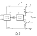
- a block diagram of an example of a power supply suitable for incorporation of the present invention is shown in FIG. 1.
- a power supply 10 includes a voltage regulator 12, output terminals 14 and 16, sense terminals 20 and 22, and a sensing circuit 24.
- Voltage regulator 12 receives an input voltage +Vin and -Vin and produces a regulated output voltage +Vout and -Vout.
- the outputs of voltage regulator 12 are connected to output terminals 14 and 16, respectively.
- Voltage regulator 12 also receives an error signal from sensing circuit 24. The magnitude of the output voltage is controlled by voltage regulator 12 in response to the error signal.
- Output terminals 14 and 16 may be coupled to a load 30, represented as a resistor R LOAD , by power supply leads 32 and 34, respectively.
- Power supply 10 supplies a regulated voltage to load 30 via output terminals 14 and 16 and power supply leads 32 and 34.
- Sensing circuit 24 has a first input connected to sense terminal 20 and a second input connected to sense terminal 22.
- a resistor 40 is connected between output terminal 14 and sense terminal 20, and a resistor 42 is connected between output terminal 16 and sense terminal 22.
- the error signal produced by sensing circuit 24 depends on the voltage between sense terminals 20 and 22.
- Sensing circuit 24 is configured to provide negative feedback.
- Sense terminals 20 and 22 may be connected to load 30 by sense leads 50 and 52, respectively. In this configuration, sensing circuit 24 senses the voltage across load 30. As noted above, the voltage across load 30 may differ from the voltage between output terminals 14 and 16 due to the resistance of power supply leads 32 and 34.
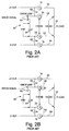
- FIG. 2A A simplified partial schematic diagram of a prior art power supply configured for remote sensing is shown in FIG. 2A.
- a simplified partial schematic diagram of the prior art power supply of FIG. 2A configured for local sensing is shown in FIG. 2B.
- a sensing circuit 80 configured to provide negative feedback, includes an error amplifier 82 and a reference voltage source 84.
- Sense terminal 20 is connected to a positive input of error amplifier 82, and sense terminal 22 is connected through reference voltage source 84 to the negative input of error amplifier 82.
- the output of error amplifier 82 is the error signal, which represents the difference between the sense voltage V SENSE between sense terminals 20 and 22, and the reference voltage V REF produced by reference voltage source 84.
- a 100 ohm resistor 86 for example, may be connected between sense terminal 20 and output terminal 14, and a 100 ohm resistor 88, for example, may be connected between sense terminal 22 and output terminal 16.
- sense lead 50 is connected between sense terminal 20 and one side of load 30, and sense lead 52 is connected between sense terminal 22 and the other side of load 30.
- Sensing circuit 80 thus measures the voltage at load 30.
- sense leads 50 and 52 are removed.
- a local sense lead 90 is connected between sense terminal 20 and output terminal 14, and a local sense lead 92 is connected between sense terminal 22 and output terminal 16.
- Sensing circuit 80 thus measures the voltage between output terminals 14 and 16. Each time the power supply is changed from remote sensing to local sensing, or vice versa, local sense leads 90 and 92 must be connected or disconnected.
- FIG. 3 A simplified partial schematic diagram of an example of a power supply in accordance with the present invention is shown in FIG. 3.
- sense lead 50 is connected from sense terminal 20 to one end of load 30, and sense lead 52 is connected from sense terminal 22 to the other end of load 30.
- remote sense leads 50 and 52 are removed, but no connection is required between sense terminal 20 and output terminal 14 or between sense terminal 22 and output terminal 16.
- a 10K ohm resistor 100 is connected between sense terminal 20 and output terminal 14, and a 10K ohm resistor 102 is connected between sense terminal 22 and output terminal 16.
- a sensing circuit 120 includes a differential amplifier 124, an error amplifier 126 and a reference voltage source 128.
- Sense terminal 20 is connected to a first input 130 of differential amplifier 124, and sense terminal 22 is connected to a second input 132 of differential amplifier 124.
- An output 134 of differential amplifier 124 is connected to a positive input of error amplifier 126.
- Reference voltage source 128 is connected between a negative input of error amplifier 126 and the negative output voltage -Vout of the power supply.
- the output of error amplifier 126 is the error signal supplied to voltage regulator 12 (FIG. 1).
- Sensing circuit 120 is configured to provide negative feedback to voltage regulator 12.
- a variety of different negative feedback configurations may be utilized within the scope of the invention.
- the input connections to differential amplifier 124 may be reversed if the sensing circuit 120 is provided with an additional 180° phase shift.
- differential amplifier 124 has a three operational amplifier configuration.
- an operational amplifier 140 has a positive input connected through a resistor 142 to the negative output voltage -Vout and has a negative input connected through a feedback resistor 144 to its output.
- the output of operational amplifier 140 is the output 134 of differential amplifier 124.
- Each of the operational amplifiers 150 and 152 is connected in a buffer amplifier configuration wherein the output is connected to a negative input.
- the buffer amplifier configuration provides high input impedance.
- Input 130 of differential amplifier 124 is connected to a positive input of operational amplifier 150, and input 132 of differential amplifier 124 is connected to a positive input of operational amplifier 152.
- Sense terminal 20 is thus connected through operational amplifier 150 and a resistor 154 to a positive input of operational amplifier 140.
- Sense terminal 22 is thus connected through operational amplifier 152 and a resistor 156 to the negative input of operational amplifier 140.
- differential amplifier 154 form a unity gain amplifier having extremely low input bias current.
- differential amplifier 124 An example of a suitable differential amplifier 124 is the type INA114 precision instrumentation amplifier sold by Burr-Brown. This amplifier has an input bias current of 2 nanoamps maximum at 25°C. It will be understood that a variety of differential amplifiers may be utilized within the scope of the present invention.
- the differential amplifier 124 should have very low input bias current, preferably less than 25 nanoamps. The requirements for differential amplifier 124 can be satisfied by most three operational amplifier instrumentation amplifiers. Another requirement of differential amplifier 124 is that its power supply range must be high enough that its input common mode range is not exceeded.
- Differential amplifier 124 re-references the sense voltage V SENSE at inputs 130 and 132 to the negative output voltage -Vout. Thus, the output 134 of differential amplifier 124 and the reference voltage V REF produced by reference voltage source 128 are both referenced to the negative output voltage -Vout.
- the power supply of FIG. 3 functions as a remote sensed power supply when sense leads 50 and 52 are connected to load 30 and functions as a locally sensed power supply when sense leads 50 and 52 are not connected. It is not necessary to connect sense terminal 20 to output terminal 14 or to connect sense terminal 22 to output terminal 16 for local sensing.
- the power supply thus operates in a remote sensing mode when sense leads 50 and 52 are connected to the load and automatically operates in a local sensing mode when sense leads 50 and 52 are not connected to the load.
- differential amplifier 124 must have low input bias current to limit the voltage drop across resistors 100 and 102. This ensures that the sense voltage V SENSE between sense terminals 20 and 22 is very close to the voltage between output terminals 14 and 16.
- each resistor has a voltage drop of 10 microvolts per nanoamp of bias current required by differential amplifier 124.
- the voltage drop across each resistor 100, 102 is 20 microvolts.
- the voltage drop across each resistor 100, 102 is less than about 250 microvolts in the local sensing mode.
- the power supply regulates the load voltage V LOAD at the load.
- resistors 100 and 102 cause a voltage division between the voltage sensed at the load and the voltage that appears at sense terminals 20 and 22 because of the resistance of sense leads 50 and 52.
- the resistor values should be chosen to limit the error caused by the voltage drop across sense leads 50 and 52.
- resistors 100 and 102 have values of 10K ohms and each sense lead 50 and 52 has a resistance of 1 ohm
- each sense lead has a voltage drop of approximately 10 microvolts per lead per 100 millivolts of voltage drop in the corresponding power supply lead 32 or 34. That is, the voltage drop across each sense lead 50, 52 is reduced by a factor of 10 -4 in comparison with the voltage drop cross the corresponding power supply lead 32, 34.
- the values of resistors 100 and 102 are selected as a compromise between two conflicting requirements: (1) the need for a minimal or nearly minimal voltage drop across resistors 100 and 102 when the power supply is operated in local sensing mode (with sense leads 50 and 52 removed), and (2) the need for a minimal or nearly minimal voltage drop across sense leads 50 and 52 when the power supply is operated in the remote sensing mode. Both of these requirements are met satisfactorily by resistor values of 10K ohms for typical parameter values set forth above.
- the values of resistors 100 and 102 are preferably in a range of about 1K ohms to 100K ohms, but we not limited to this range. It will be understood that the selection of resistor values depends on a number of factors, including the power supply voltage, the bias current required by the differential amplifier, the resistance of sense leads 50 and 52, and the desired power supply accuracy.
- the present invention eliminates the need for the operator to make connections between the sense terminals and the output terminals of the supply when local sensing is utilized, thereby offering ease of use to the operator.
- the desired output voltage can be programmed into the power supply, and that voltage appears at the output terminals.
- the invention combines the convenience of a locally sensed laboratory power supply with the precision of a remote sensed laboratory power supply.
- the invention does not require the sense terminals to be located physically close to the output terminals, since they are not connected together for local sensing.
- the invention may be incorporated into general purpose laboratory power supplies to provide optional remote sensing, without adversely affecting the convenience of use of the general purpose laboratory power supply.
Abstract
Description
- This invention relates to power supplies and, more particularly, to power supplies which perform automatic local sensing.
- Typical laboratory power supplies use local voltage sensing, in which the output voltage is regulated at the output terminals on the power supply. A laboratory power supply that uses local sensing is convenient to use, but the voltage across the load is not well regulated because of voltage drops in the power supply leads between the power supply output terminals and the load. The voltage drop depends on the resistance of the power supply leads and the current drawn by the load.
- Precision laboratory power supplies may include a remote sensing feature that regulates the voltage at the load. In such supplies, sense terminals on the power supply are connected to the load separately from the current-carrying connections. Precision laboratory power supplies may also be set up for local sensing by connecting the sense terminals to the power supply output terminals. This type of power supply is inconvenient to use as a locally sensed power supply, because it is necessary to connect the sense terminals to the power supply output terminals. Some supplies include resistors connected between the sense terminals and the output terminals. Even when the resistors are present, the current through them is generally high enough to cause poor regulation at the power supply output terminals, if the sense terminals are not connected to the output terminals. Thus, the failure to connect the sense terminals to the output terminals in the locally sensed mode may result in poor regulation and unpredictable behavior.
- Another approach to local sensing is disclosed by J.D. Felps in "Automatic Local Sensing Improves Regulation," EDN, January 4, 1996, pages 102-104. A precise current is passed through the resistors that interconnect the sense terminals and the supply output terminals. Thus, the voltage at the power supply output terminals increases by a fixed amount, such as for example 2%, when remote sensing is not utilized. The voltage increase may compensate for the voltage drop through the leads that carry current to the load. This approach permits use of one power supply in multiple products, but is not particularly useful in laboratory power supplies. Accordingly, there is a need for improved sensing circuitry for controlling power supply voltages.
- According to one aspect of the invention, a power supply for supplying a regulated voltage to a load is provided. The power supply comprises a voltage regulator for generating the regulated voltage in response to an input voltage and an error signal, first and second output terminals connected to the voltage regulator for coupling the power supply to the load, first and second sense terminals and a sensing circuit for generating the error signal. The sensing circuit comprises a high input impedance differential amplifier having first and second inputs respectively coupled to the first and second sense terminals for measuring a sense voltage between the sense terminals. The power supply further comprises a first resistor connected between the first output terminal and the first sense terminal, and a second resistor connected between the second output terminal and the second sense terminal.
- According to one feature of the invention, the first and second resistors may have values selected to produce a minimal or nearly minimal voltage difference between each of the output terminals and the respective sense terminals when the sense terminals are not connected to the load, and to produce a minimal or nearly minimal voltage difference between each of the sense terminals and respective sides of the load when the sense terminals are connected to the load.
- According to another feature of the invention, the differential amplifier may comprise an operational amplifier having first and second inputs, a first buffer amplifier coupled between the first sense terminal and the first input of the operational amplifier and a second buffer amplifier coupled between the second sense terminal and the second input of the operational amplifier. The differential amplifier may comprise an instrumentation amplifier. Preferably, the differential amplifier requires bias currents to the first and second inputs less than about 25 nanoamps.
- According to a further feature of the invention, the first and second resistors have values selected to produce a voltage difference less than about 250 microvolts between each of the output terminals and the respective sense terminals when the sense terminals are not connected to the load. The first and second resistors preferably have values in a range of about 1 kilohm to 100 kilohms.
- For a better understanding of the present invention, reference is made to the accompanying drawings, which are incorporated herein by reference and in which:
- FIG. 1 is a block diagram of a power supply suitable for incorporation of the present invention;
- FIG. 2A is a simplified partial schematic diagram of a prior art power supply configured for remote sensing;
- FIG. 2B is a simplified partial schematic diagram of the power supply of FIG. 2A configured for local sensing; and
- FIG. 3 is a simplified partial schematic diagram of an example of a power supply in accordance with the present invention.
-
- A block diagram of an example of a power supply suitable for incorporation of the present invention is shown in FIG. 1. A
power supply 10 includes avoltage regulator 12,output terminals sense terminals sensing circuit 24.Voltage regulator 12 receives an input voltage +Vin and -Vin and produces a regulated output voltage +Vout and -Vout. The outputs ofvoltage regulator 12 are connected tooutput terminals Voltage regulator 12 also receives an error signal fromsensing circuit 24. The magnitude of the output voltage is controlled byvoltage regulator 12 in response to the error signal.Output terminals load 30, represented as a resistor RLOAD, by power supply leads 32 and 34, respectively.Power supply 10 supplies a regulated voltage to load 30 viaoutput terminals -
Sensing circuit 24 has a first input connected tosense terminal 20 and a second input connected tosense terminal 22. Aresistor 40 is connected betweenoutput terminal 14 andsense terminal 20, and aresistor 42 is connected betweenoutput terminal 16 andsense terminal 22. The error signal produced bysensing circuit 24 depends on the voltage betweensense terminals Sensing circuit 24 is configured to provide negative feedback.Sense terminals circuit 24 senses the voltage acrossload 30. As noted above, the voltage acrossload 30 may differ from the voltage betweenoutput terminals - A simplified partial schematic diagram of a prior art power supply configured for remote sensing is shown in FIG. 2A. A simplified partial schematic diagram of the prior art power supply of FIG. 2A configured for local sensing is shown in FIG. 2B. A
sensing circuit 80, configured to provide negative feedback, includes anerror amplifier 82 and areference voltage source 84.Sense terminal 20 is connected to a positive input oferror amplifier 82, andsense terminal 22 is connected throughreference voltage source 84 to the negative input oferror amplifier 82. The output oferror amplifier 82 is the error signal, which represents the difference between the sense voltage VSENSE betweensense terminals reference voltage source 84. A 100ohm resistor 86, for example, may be connected betweensense terminal 20 andoutput terminal 14, and a 100ohm resistor 88, for example, may be connected betweensense terminal 22 andoutput terminal 16. - In the remote sensing configuration,
sense lead 50 is connected betweensense terminal 20 and one side ofload 30, andsense lead 52 is connected betweensense terminal 22 and the other side ofload 30.Sensing circuit 80 thus measures the voltage atload 30. - In the local sensing configuration of FIG. 2B, sense leads 50 and 52 are removed. A local sense lead 90 is connected between
sense terminal 20 andoutput terminal 14, and alocal sense lead 92 is connected betweensense terminal 22 andoutput terminal 16.Sensing circuit 80 thus measures the voltage betweenoutput terminals - A simplified partial schematic diagram of an example of a power supply in accordance with the present invention is shown in FIG. 3. For remote sensing,
sense lead 50 is connected fromsense terminal 20 to one end ofload 30, andsense lead 52 is connected fromsense terminal 22 to the other end ofload 30. For local sensing, remote sense leads 50 and 52 are removed, but no connection is required betweensense terminal 20 andoutput terminal 14 or betweensense terminal 22 andoutput terminal 16. A10K ohm resistor 100 is connected betweensense terminal 20 andoutput terminal 14, and a10K ohm resistor 102 is connected betweensense terminal 22 andoutput terminal 16. - A sensing circuit 120 includes a
differential amplifier 124, anerror amplifier 126 and areference voltage source 128.Sense terminal 20 is connected to afirst input 130 ofdifferential amplifier 124, andsense terminal 22 is connected to asecond input 132 ofdifferential amplifier 124. Anoutput 134 ofdifferential amplifier 124 is connected to a positive input oferror amplifier 126.Reference voltage source 128 is connected between a negative input oferror amplifier 126 and the negative output voltage -Vout of the power supply. The output oferror amplifier 126 is the error signal supplied to voltage regulator 12 (FIG. 1). - Sensing circuit 120 is configured to provide negative feedback to
voltage regulator 12. A variety of different negative feedback configurations may be utilized within the scope of the invention. For example, the input connections todifferential amplifier 124 may be reversed if the sensing circuit 120 is provided with an additional 180° phase shift. - In the example of FIG. 3,
differential amplifier 124 has a three operational amplifier configuration. In particular, anoperational amplifier 140 has a positive input connected through a resistor 142 to the negative output voltage -Vout and has a negative input connected through afeedback resistor 144 to its output. The output ofoperational amplifier 140 is theoutput 134 ofdifferential amplifier 124. Each of theoperational amplifiers differential amplifier 124 is connected to a positive input ofoperational amplifier 150, andinput 132 ofdifferential amplifier 124 is connected to a positive input ofoperational amplifier 152.Sense terminal 20 is thus connected throughoperational amplifier 150 and aresistor 154 to a positive input ofoperational amplifier 140.Sense terminal 22 is thus connected throughoperational amplifier 152 and aresistor 156 to the negative input ofoperational amplifier 140. In combination, the components ofdifferential amplifier 154 form a unity gain amplifier having extremely low input bias current. - An example of a suitable
differential amplifier 124 is the type INA114 precision instrumentation amplifier sold by Burr-Brown. This amplifier has an input bias current of 2 nanoamps maximum at 25°C. It will be understood that a variety of differential amplifiers may be utilized within the scope of the present invention. Thedifferential amplifier 124 should have very low input bias current, preferably less than 25 nanoamps. The requirements fordifferential amplifier 124 can be satisfied by most three operational amplifier instrumentation amplifiers. Another requirement ofdifferential amplifier 124 is that its power supply range must be high enough that its input common mode range is not exceeded.Differential amplifier 124 re-references the sense voltage VSENSE atinputs output 134 ofdifferential amplifier 124 and the reference voltage VREF produced byreference voltage source 128 are both referenced to the negative output voltage -Vout. - As indicated above, the power supply of FIG. 3 functions as a remote sensed power supply when sense leads 50 and 52 are connected to load 30 and functions as a locally sensed power supply when sense leads 50 and 52 are not connected. It is not necessary to connect
sense terminal 20 tooutput terminal 14 or to connectsense terminal 22 tooutput terminal 16 for local sensing. The power supply thus operates in a remote sensing mode when sense leads 50 and 52 are connected to the load and automatically operates in a local sensing mode when sense leads 50 and 52 are not connected to the load. - As indicated above,
differential amplifier 124 must have low input bias current to limit the voltage drop acrossresistors sense terminals output terminals resistors differential amplifier 124. Thus, in the above example wheredifferential amplifier 124 has a maximum bias current of 2 nanoamps, the voltage drop across eachresistor resistor - In the remote sensing mode, the power supply regulates the load voltage VLOAD at the load. In the remote sensing mode,
resistors sense terminals resistors sense lead power supply lead sense lead power supply lead - In general, the values of
resistors resistors resistors - The present invention eliminates the need for the operator to make connections between the sense terminals and the output terminals of the supply when local sensing is utilized, thereby offering ease of use to the operator. The desired output voltage can be programmed into the power supply, and that voltage appears at the output terminals. The invention combines the convenience of a locally sensed laboratory power supply with the precision of a remote sensed laboratory power supply. The invention does not require the sense terminals to be located physically close to the output terminals, since they are not connected together for local sensing. The invention may be incorporated into general purpose laboratory power supplies to provide optional remote sensing, without adversely affecting the convenience of use of the general purpose laboratory power supply.
- While there have been shown and described what are at present considered the preferred embodiments of the present invention, it will be obvious to those skilled in the art that various changes and modifications may be made therein without departing from the scope of the invention as defined by the appended claims.
Claims (10)
- A power supply for supplying a regulated voltage to a load, comprising:a voltage regulator (12) for generating said regulated voltage in response to an input voltage and an error signal;first and second output terminals (14, 16) connected to said voltage regulator for coupling the power supply to the load (30);first and second sense terminals (20, 22);a sensing circuit for generating said error signal, said sensing circuit comprising a high input impedance differential amplifier (124) having first and second inputs (130, 132) respectively coupled to said first and second sense terminals (20, 22) for measuring a sense voltage between said sense terminals;a first resistor (100) connected between said first output terminal (14) and said first sense terminal (20); anda second resistor (102) connected between said second output terminal (16) and said second sense terminal (22), wherein said first and second resistors (100, 102) have values selected to produce a minimal or nearly minimal voltage difference between each of said output terminals and the respective sense terminals when said sense terminals are not connected to the load, and to produce a minimal or nearly minimal voltage difference between each of said sense terminals and respective sides of the load when said sense terminals are connected to the load.
- A power supply as defined in claim 1 wherein said differential amplifier comprises an instrumentation amplifier.
- A power supply as defined in claim 1 wherein said differential amplifier comprises an operational amplifier having first and second inputs, a first buffer amplifier coupled between said first sense terminal and the first input of said operational amplifier and a second buffer amplifier coupled between said second sense terminal and the second input of said operational amplifier.
- A power supply as defined in claim 1 wherein said differential amplifier requires bias
- A power supply for supplying a regulated voltage to a load, comprising:a voltage regulator (12) for generating said regulated voltage in response to an input voltage and an error signal;first and second output terminals (14, 16) connected to said voltage regulator for coupling the power supply to the load (30);first and second sense terminals (20, 22);a sensing circuit for generating said error signal, said sensing circuit comprising a high input impedance differential amplifier (124) having first and second inputs (130, 132) respectively coupled to said first and second sense terminals (20, 22) for measuring a sense voltage between said sense terminals, said differential amplifier comprising an operational amplifier (140) having first and second inputs, a first buffer amplifier (150) coupled between said first sense terminal (20) and the first input of said operational amplifier and a second buffer amplifier (152) coupled between said second sense terminal (22) and the second input of said operational amplifier;a first resistor (100) connected between said first output terminal (14) and said first sense terminal (20); anda second resistor (102) connected between said second output terminal (16) and said second sense terminal (22).
- A power supply as defined in claim 5 wherein said differential amplifier has input bias currents less than about 25 nanoamps.
- A power supply as defined in claim 5 wherein said differential amplifier comprises an instrumentation amplifier.
- A power supply for supplying a regulated voltage to a load, comprising:a voltage regulator (12) for generating said regulated voltage in response to an input voltage and an error signal;first and second output terminals (14, 16) connected to said voltage regulator for coupling the power supply to the load (30);first and second sense terminals (20, 22);a sensing circuit for generating said error signal, said sensing circuit comprising a high input impedance differential amplifier (124) having first and second inputs (130, 132) respectively coupled to said first and second sense terminals (20, 22) for measuring a sense voltage between said sense terminals;a first resistor (100) connected between said first output terminal (14) and said first sense terminal (20); anda second resistor (102) connected between said second output terminal (16) and said second sense terminal (22), wherein said first and second resistors (100, 102) have values selected to produce a voltage difference less than about 250 microvolts between each of said output terminals and the respective sense terminals when said sense terminals are not connected to the load.
- A power supply as defined in claim 8 wherein said differential amplifier comprises an instrumentation amplifier.
- A power supply as defined in claim 8 wherein said differential amplifier comprises an operational amplifier having first and second inputs, a first buffer amplifier coupled between said first sense terminal and the first input of said operational amplifier and a second buffer amplifier coupled between said second sense terminal and the second input of said operational amplifier.
Applications Claiming Priority (2)
| Application Number | Priority Date | Filing Date | Title |
|---|---|---|---|
| US184473 | 1998-11-02 | ||
| US09/184,473 US5977757A (en) | 1998-11-02 | 1998-11-02 | Power supply having automatic voltage sensing |
Publications (1)
| Publication Number | Publication Date |
|---|---|
| EP0999453A1 true EP0999453A1 (en) | 2000-05-10 |
Family
ID=22677021
Family Applications (1)
| Application Number | Title | Priority Date | Filing Date |
|---|---|---|---|
| EP99115491A Withdrawn EP0999453A1 (en) | 1998-11-02 | 1999-08-05 | Power supply having automatic voltage sensing |
Country Status (3)
| Country | Link |
|---|---|
| US (1) | US5977757A (en) |
| EP (1) | EP0999453A1 (en) |
| JP (1) | JP2000148257A (en) |
Cited By (1)
| Publication number | Priority date | Publication date | Assignee | Title |
|---|---|---|---|---|
| CN102253256A (en) * | 2011-04-19 | 2011-11-23 | 深圳茂硕电源科技股份有限公司 | High-power power supply load meter |
Families Citing this family (15)
| Publication number | Priority date | Publication date | Assignee | Title |
|---|---|---|---|---|
| WO2000069040A2 (en) * | 1999-01-29 | 2000-11-16 | Terayon Communication Systems, Inc. | Power delivery system with compensation for line loss |
| US6181027B1 (en) * | 1999-02-26 | 2001-01-30 | International Business Machine Corp. | DC power distribution |
| US6680642B2 (en) * | 2002-05-23 | 2004-01-20 | Innersea Technology | Analog bipolar current source |
| DE10397018A5 (en) | 2002-07-02 | 2015-05-28 | Panasonic Healthcare Holdings Co., Ltd. | Biosensor, biosensor chip and biosensor device |
| US7514911B2 (en) * | 2004-05-13 | 2009-04-07 | Marvell World Trade Ltd. | Voltage regulator feedback protection method and apparatus |
| US20060022525A1 (en) * | 2004-08-02 | 2006-02-02 | Landry Clet A | Remote sensing regulated voltage power supply |
| US7394276B2 (en) * | 2006-01-17 | 2008-07-01 | International Business Machines Corporation | Active cancellation matrix for process parameter measurements |
| US8138736B2 (en) * | 2009-01-20 | 2012-03-20 | Securaplane Technologies, Inc. | Power system having a local sense control dominant over a remote sense control to avoid effects of interconnection failure modes |
| TWI451224B (en) * | 2011-12-21 | 2014-09-01 | Anpec Electronics Corp | Dynamic voltage adjustment device and power transmission system using the same |
| US9304524B2 (en) * | 2014-08-24 | 2016-04-05 | Freescale Semiconductor, Inc. | Voltage regulation system for integrated circuit |
| US9436191B2 (en) * | 2014-09-16 | 2016-09-06 | Freescale Semiconductor, Inc. | Voltage regulation system for integrated circuit |
| JP6090275B2 (en) * | 2014-09-25 | 2017-03-08 | 株式会社デンソー | Power converter |
| US10110116B1 (en) * | 2017-06-13 | 2018-10-23 | International Business Machines Corporation | Implementing voltage sense point switching for regulators |
| WO2020129767A1 (en) * | 2018-12-18 | 2020-06-25 | 三菱電機株式会社 | Dc-dc converter |
| CN111610844A (en) * | 2020-05-25 | 2020-09-01 | 深圳市信锐网科技术有限公司 | Output voltage adjusting method, device, equipment and readable storage medium |
Citations (7)
| Publication number | Priority date | Publication date | Assignee | Title |
|---|---|---|---|---|
| US2989694A (en) * | 1958-03-17 | 1961-06-20 | Cutler Hammer Inc | Fault detector |
| US3532936A (en) * | 1969-01-14 | 1970-10-06 | Automatic Elect Lab | Protective circuit for direct current voltage regulators |
| US3754221A (en) * | 1970-12-22 | 1973-08-21 | M Stelter | Ground fault detector and method of ground fault detection |
| US3818274A (en) * | 1973-03-29 | 1974-06-18 | Gte Automatic Electric Lab Inc | Remote sensing voltage clamping circuit |
| DE2927264B1 (en) * | 1979-07-05 | 1980-10-02 | Siemens Ag | Circuit arrangement with at least one supply voltage source to be switched through |
| US4551668A (en) * | 1982-07-28 | 1985-11-05 | Reliance Electric Company | Voltage sensing at loads remotely connected to power supplies |
| US5146397A (en) * | 1989-12-19 | 1992-09-08 | U. S. Philips Corporation | Power supply device with unbalance monitoring circuit |
Family Cites Families (4)
| Publication number | Priority date | Publication date | Assignee | Title |
|---|---|---|---|---|
| DE3128116A1 (en) * | 1981-07-16 | 1983-02-03 | Robert Bosch Gmbh, 7000 Stuttgart | SHORT-CIRCUIT-DRIVE CONTROL ARRANGEMENT FOR AN ELECTRICAL CONSUMER |
| US5734259A (en) * | 1995-09-29 | 1998-03-31 | Cherry Semiconductor Corporation | Balanced delta current method for current control in a hysteretic power supply |
| US5680036A (en) * | 1996-03-19 | 1997-10-21 | Compaq Computer Corporation | Logarithmic power compensation for a switching power supply |
| US5889393A (en) * | 1997-09-29 | 1999-03-30 | Impala Linear Corporation | Voltage regulator having error and transconductance amplifiers to define multiple poles |
-
1998
- 1998-11-02 US US09/184,473 patent/US5977757A/en not_active Expired - Fee Related
-
1999
- 1999-08-05 EP EP99115491A patent/EP0999453A1/en not_active Withdrawn
- 1999-10-29 JP JP11308549A patent/JP2000148257A/en active Pending
Patent Citations (7)
| Publication number | Priority date | Publication date | Assignee | Title |
|---|---|---|---|---|
| US2989694A (en) * | 1958-03-17 | 1961-06-20 | Cutler Hammer Inc | Fault detector |
| US3532936A (en) * | 1969-01-14 | 1970-10-06 | Automatic Elect Lab | Protective circuit for direct current voltage regulators |
| US3754221A (en) * | 1970-12-22 | 1973-08-21 | M Stelter | Ground fault detector and method of ground fault detection |
| US3818274A (en) * | 1973-03-29 | 1974-06-18 | Gte Automatic Electric Lab Inc | Remote sensing voltage clamping circuit |
| DE2927264B1 (en) * | 1979-07-05 | 1980-10-02 | Siemens Ag | Circuit arrangement with at least one supply voltage source to be switched through |
| US4551668A (en) * | 1982-07-28 | 1985-11-05 | Reliance Electric Company | Voltage sensing at loads remotely connected to power supplies |
| US5146397A (en) * | 1989-12-19 | 1992-09-08 | U. S. Philips Corporation | Power supply device with unbalance monitoring circuit |
Cited By (2)
| Publication number | Priority date | Publication date | Assignee | Title |
|---|---|---|---|---|
| CN102253256A (en) * | 2011-04-19 | 2011-11-23 | 深圳茂硕电源科技股份有限公司 | High-power power supply load meter |
| CN102253256B (en) * | 2011-04-19 | 2016-07-06 | 茂硕电源科技股份有限公司 | A kind of large power supply load meter |
Also Published As
| Publication number | Publication date |
|---|---|
| JP2000148257A (en) | 2000-05-26 |
| US5977757A (en) | 1999-11-02 |
Similar Documents
| Publication | Publication Date | Title |
|---|---|---|
| US5977757A (en) | Power supply having automatic voltage sensing | |
| CA1296396C (en) | Error amplifier for use with parallel operated autonomous current or voltage regulators using transconductance type power amplifiers | |
| US5686821A (en) | Stable low dropout voltage regulator controller | |
| US4963814A (en) | Regulated bifurcated power supply | |
| EP1410126B1 (en) | Differential current source with active common mode reduction | |
| EP0023750A2 (en) | Sample and hold circuit | |
| JPH027206B2 (en) | ||
| EP0355119B1 (en) | Voltage regulator | |
| KR970003720B1 (en) | Multi-output feedback amplifier | |
| US4217555A (en) | Amplifier circuit arrangement with stabilized power-supply current | |
| US4929908A (en) | Gain controllable amplifier circuit | |
| US11018630B2 (en) | Disabled mode error reduction for high-voltage bilateral operational amplifier current source | |
| EP0502056A1 (en) | Difference amplifier apparatus employing an input attenuator network. | |
| US4544875A (en) | Variable current transducer system | |
| EP0031182B1 (en) | Amplifier arrangement with parallel-operated amplifier sections | |
| US4502003A (en) | Two wire circuit having an adjustable span | |
| EP0182201A1 (en) | Speed control apparatus for a DC motor | |
| US4727335A (en) | Gain-controlled amplifier | |
| US4723278A (en) | Voice circuit of telephone | |
| US4853644A (en) | Differential amplifier circuit | |
| TWI833291B (en) | Voltage regulating circuit | |
| JPH0247616Y2 (en) | ||
| US6545539B1 (en) | Amplifier for use in a mobile phone | |
| JPS5818715A (en) | Voltage stabilization circuit | |
| JP3322145B2 (en) | Current control circuit |
Legal Events
| Date | Code | Title | Description |
|---|---|---|---|
| PUAI | Public reference made under article 153(3) epc to a published international application that has entered the european phase |
Free format text: ORIGINAL CODE: 0009012 |
|
| AK | Designated contracting states |
Kind code of ref document: A1 Designated state(s): DE FR GB |
|
| AX | Request for extension of the european patent |
Free format text: AL;LT;LV;MK;RO;SI |
|
| 17P | Request for examination filed |
Effective date: 20000703 |
|
| AKX | Designation fees paid |
Free format text: DE FR GB |
|
| RAP1 | Party data changed (applicant data changed or rights of an application transferred) |
Owner name: AGILENT TECHNOLOGIES, INC. |
|
| RAP1 | Party data changed (applicant data changed or rights of an application transferred) |
Owner name: AGILENT TECHNOLOGIES INC. |
|
| RAP1 | Party data changed (applicant data changed or rights of an application transferred) |
Owner name: AGILENT TECHNOLOGIES INC. A DELAWARE CORPORATION |
|
| RAP1 | Party data changed (applicant data changed or rights of an application transferred) |
Owner name: AGILENT TECHNOLOGIES, INC. (A DELAWARE CORPORATION |
|
| 17Q | First examination report despatched |
Effective date: 20031111 |
|
| STAA | Information on the status of an ep patent application or granted ep patent |
Free format text: STATUS: THE APPLICATION HAS BEEN WITHDRAWN |
|
| 18W | Application withdrawn |
Effective date: 20040628 |