EP0998403B1 - Sliding bogie trailers - Google Patents
Sliding bogie trailers Download PDFInfo
- Publication number
- EP0998403B1 EP0998403B1 EP98935145A EP98935145A EP0998403B1 EP 0998403 B1 EP0998403 B1 EP 0998403B1 EP 98935145 A EP98935145 A EP 98935145A EP 98935145 A EP98935145 A EP 98935145A EP 0998403 B1 EP0998403 B1 EP 0998403B1
- Authority
- EP
- European Patent Office
- Prior art keywords
- section
- sections
- trailer
- extendible
- locking means
- Prior art date
- Legal status (The legal status is an assumption and is not a legal conclusion. Google has not performed a legal analysis and makes no representation as to the accuracy of the status listed.)
- Expired - Lifetime
Links
Images
Classifications
-
- B—PERFORMING OPERATIONS; TRANSPORTING
- B60—VEHICLES IN GENERAL
- B60P—VEHICLES ADAPTED FOR LOAD TRANSPORTATION OR TO TRANSPORT, TO CARRY, OR TO COMPRISE SPECIAL LOADS OR OBJECTS
- B60P1/00—Vehicles predominantly for transporting loads and modified to facilitate loading, consolidating the load, or unloading
- B60P1/64—Vehicles predominantly for transporting loads and modified to facilitate loading, consolidating the load, or unloading the load supporting or containing element being readily removable
- B60P1/6418—Vehicles predominantly for transporting loads and modified to facilitate loading, consolidating the load, or unloading the load supporting or containing element being readily removable the load-transporting element being a container or similar
- B60P1/6481—Specially adapted for carrying different numbers of container or containers of different sizes
Definitions
- the present invention relates to sliding bogie trailers, and in particular to extendible skeletal or extendible flatbed truck trailers that may be used for carrying loads such as container loads or pallets, according to the features of the preamble of independent claim 1, and to a method relaled thereto according to claim 13.
- Skeletal truck trailers often have a rear sliding bogie section and a forwards chassis section for connection to a tractor fifth wheel.
- This arrangement allows such trailers to be extendible between two lengths, for example 6.1 m (20 feet) and 12.2 m (40 feet).
- the length of the trailer is locked at either of these lengths for mounting of containers with these lengths.
- a 13.7 m (45 feet) container may also be carried on a 12.2 m trailer.
- the length of the trailer may be locked in the extended position to permit greater axle loading, according to the law. For example, a 6.1 m container above a certain weight may be required by law to be carried by a 12.2 m trailer in order to spread the axle loading.
- trailers There are many varieties of flatbed trailers that may be connected to and towed by a truck. Some consist mainly of a floored surface above the trailer frame; others have additional structural elements, for example, fold-down sides, curtain sides or top, rigid sides or top, and vertical side pillars. Such trailers are often used to transport a wide variety of items such as palletised goods, concrete or steel beams and logs.
- the present invention provides an extendible trailer comprising: a wheeled bogie section; braking means including wheel brakes by which road-going wheels may be braked; a chassis section forwards of the bogie section, and relatively moveable with respect to the bogie section between an extended and a retracted position; section locking means by which the sections may be releasably secured in said positions; characterised in that the trailer has control means arranged to control the section locking means and the braking means so that the wheel brakes are engaged prior to and during the relative movement of the sections.
- the control means may also be arranged to control the section locking means and the braking means so that the wheel brakes are disengaged after the relative movement of the sections.
- the trailer may be a skeletal, flatbed or any other type of trailer that may be connected to a tractor or towed behind any other type of vehicle.
- the control means may include an air driven mechanism connected, for example, to an air supply.
- air supplies are common on trailers having air-driven braking mechanisms.
- section locking means comprises on one section a moveable member which may be moved in order to release the section locking means.
- the braking means can including a sensor to detect the movement of the movable member to engage wheel brakes prior to and during the relative movement of the sections.
- movable member as used herein includes arrangement having more than one moving part.
- another or the same sensor can also be used to detect the movement of the movable member when the section locking means secures the sections, for example movement in an opposite direction, so that the wheel brakes may be released after the relative movement of the sections.
- the sensor could, for example, detect the activation of an air supply to a movable member, for example measuring air pressure.
- the sensor detects the movement of the movable member, the brakes being engaged when the movable member is in position to disengage with a passive member.
- the brakes can be released after the sensor has detected movement of the movable member to secure the sections. In this way, a direct measure may be had of the state of the section locking means.
- the section locking means may comprise on one section at least one passive, or non-movable, member that engages with a moveable member on the other section when the sections are secured in position.
- movable members there are two movable members defining opposite ends of trailer extension and a passive member is relatively movable between the movable members. Both of said movable members may then have a sensor, the control means controlling the section locking means so that both movable members are activated so that they may engage with the passive member when the sections are between extended and retracted positions. In this way, the extendible trailer can be moved from one position, and then to the other position or if needed back into the same position, whereupon the sections can be secured together.
- the movable member may be part of a fifth wheel locking mechanism on one section, the passive member being a pin on the other section.
- the fifth wheel mechanism can have a locking slide hammer to close the fifth wheel mechanism.
- the locking slide hammer is then the movable member, and the sensor can detect movement, or equivalently the presence, of the slide hammer when this is closed.
- the movable member prefferably be one, for example one of a pair, of steel pins or bolts which are inserted through and protrude laterally inwards through matching holes in one of the sections at least two extension positions.
- the slide hammer is latched open once a pin has been disengaged from the fifth wheel mechanism, the mechanism automatically engaging with the pin once the pin again enters the mechanism.
- the section securing means is operable to secure automatically the sections when the sections are moved into position. Then, a driver of a truck tractor unit connected to the trailer will not be able to drive off with the sections moved to a new position, but not yet secured into engagement with each other.
- a method of extending an extendible trailer that comprises: a wheeled bogie section; braking means including wheel brakes by which road-going wheels may be braked; a chassis section forwards of the bogie section, and relatively moveable with respect to the bogie section between an extended and a retracted position; section locking means by which the sections may be releasably secured in said positions; and control means arranged to control both the section locking means and braking means; characterised in that the method comprises the steps of:
- the method may then additional comprise after step iii) the steps of:
- the tractor When the trailer is connected to a truck tractor unit, the tractor may be used to move the sections from one position to the other position, with the driver pulling away from, or backing down upon, the trailer with its wheels braked under the control of the control means.
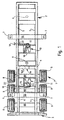
- FIG. 1 this shows a known extendible skeletal trailer 1, described more fully in patent document PCT/GB96/00361.
- the trailer has two transverse beams 55 each with a pair of standard twist lock mounting points 7 for a 6.1 m (20 feet) container.
- a front chassis section 2 has along its sides a pair of load bearing parallel steel I-beams 5 which present to each other inward facing C-sections.
- a sliding rear bogie section 3 has along its sides a pair of parallel inward facing steel C-beams 4 which are nested inside and slidable along the rear and central parts of the front C-sections.
- the front chassis section 2 has a downwardly facing king pin 6 for connection with a known fifth wheel on a tractor unit (not shown), and the rear bogie section 3 has a set of six wheels 8, three to a side, joined by three axles 88.
- the front chassis section would, of course, normally be supported by drop-down support legs (not shown) when the trailer was not connected to a tractor.
- the rear section 3 has an upwardly facing striker pin 9 which travels between a forward 10 and a rearward clasp 11 which are fixed to the front chassis section 2.
- the striker pin 9 and clasps 10,11 are in the middle of the trailer, centered on the width of the trailer.
- the trailer is shown in between the fully extended and retracted positions. In the retracted position the striker pin 9 is held by the front clasp 10, and in the extended position the striker pin is held by the rear clasp 11.
- the fifth wheel clasp mechanisms 10,11 each comprise a jaw 13 and a locking slide hammer 16, which may be manually retracted by a release arm 18.
- the arms may be pneumatically driven by an air piston.
- this prior art extendible trailer is the same as that described below.
- the truck driver would first fix all wheel brakes on, and then manually retract one of the fifth wheel release arms 18 from the closed to the open position.
- Each arm is provided with a latch 22 which engages with a feature (not shown) on the outside of the trailer to temporarily hold back the slide hammer arm 18.
- the driver would then release just the brakes for the cab wheels and drive forwards or in reverse to retract the striker pin 9 from one of the clasps 10,11 and then engage the pin in the jaw 13 of the other clasp.
- the jaw would then automatically rotate to the closed position as described above, and the latch 22 could be manually released to close the slide hammer 16, whereupon the clasp would be locked to retain the striker pin and hold the trailer sections 2,3 in the extended or retracted position.
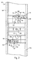
- a pair of fifth wheel clasp mechanisms 110,111 have a passive member in the form of a pin 109 which travels between and which may be engaged in either mechanism.
- the mechanisms 110,111 each have a movable member, in particular a jaw 113 and a locking slide hammer 116.
- the slide hammer 116 is spring biased into the closed position across the jaw 113.
- Each slide hammer 116 may be activated by a pneumatic piston 130 which drives the slide hammer 116.
- Each piston is driven by a pair of air lines 131,132;133,134, the arrangement inside the piston being such that each piston 130 may be positively driven in either direction, either to open or to shut across the jaw 113.
- the slide hammers each have a tapered surface 138.
- movement sensors 140,141 which have a toggle arm, 143,144, which is depressed when the slide hammer 116 is fully across the jaw 116. Otherwise, as illustrated in Figure 2, each of the toggle arms 143,144 is up.
- One of the sensors 140 is supplied with a constant air feed, and has as an output a pneumatic line 146 that is an input pneumatic line for the other sensor 141, explained in more detail below in relation to Figure 6.
- the arrangement of the piston air lines 131,132;133,134 to each piston 130 is such that air is always supplied to one or the other of the lines 131,132;133,134. In the event of air being cut to the piston 130, the spring bias keeps the slide hammer 116 engaged across the jaw 113.
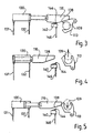
- the slide hammer 116 and sensor 140,141 arrangement is shown in more detail in Figures 3, 4 and 5.
- air is supplied to pneumatic line 131, and so the slide hammer 116 is fully across the jaw 113.
- the pin 109 is then engaged within the clasp mechanism.
- the toggle arm 144 is depressed having detected the movement of the slide hammer 116 into the engaged position. As will be explained later, this cuts the flow of air into line 146.
- Figure 5 shows the clasp awaiting the pin 109.
- the air is supplied to line 131, but the slide hammer 116 is latched back by the open jaw 113, and so cannot close the jaw.
- the clasp automatically rotates to let the slide hammer 116 engage across the jaw 113.
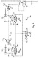
- FIG. 6 shows schematically the control means 60 for controlling the locking means.
- the control means 60 is supplied with a constant feed of air 61, whenever the trailer is connected to an air supply.
- a two position push button switch 62 mounted on a side of the trailer accessible to the driver, and controls a standard twin single pole, double throw air valve 63, one half of which is not used.
- the air from the valve 63 passes to one side 66 of a pair of similar air valves 64,65.
- the similar air valves 64,65 control the flow of air to the pistons 130.
- the air from the valve 63 passes to the other side 67 of the similar air valves 64,65.
- the arrangement is such that the air supply 66,67 is isolated from the outputs 68,69 of the similar valves 64,65.
- the outputs 68,69 are then connected to the piston air lines 131,132;133,134 described above.
- the operation of the control system 60 may now be described in more detail.
- the push button 62 is pushed or pulled to the alternate position by a driver whenever the trailer is to be extended or retracted. This switches the air supply between lines 66,67, and this switches the air supply between lines 131,132. Therefore the piston 130 which had been activated, becomes deactivated, and vice versa. This has the effect of withdrawing the one slide hammer 116 which had been across its jaw 113.
- sensor 140 is connected to a constant air feed 61.
- the output air line 146 from sensor 140 is fed into the inlet of the other sensor 141, so that the sensors 140,141 are in series. Therefore, when both sensors sense that the slide hammer is not across its jaw (i.e. both slide hammers are activated into a retracted position), the outlet 147 of sensor 141 is pressurised, and this is fed through a shuttle valve 50 to the so-called "red air line” 52, in order to switch off the air supply to this red air line 52, whereupon the wheels automatically become braked.
- the slide hammer 116 for that mechanism will automatically slide across its jaw, and this will cut the air supply through its sensor 140,141, thereby releasing the shuttle valve 50 and the brakes.
- the extendible trailer according to the invention can therefore be moved between extended and retracted positions whilst the locking of wheels is conveniently, automatically and safely controlled.
Description
Claims (15)
- An extendible trailer comprising: a wheeled bogie section (103); braking means (50,52) including wheel brakes by which road-going wheels (8) may be braked; a chassis section (102) forwards of the bogie section (103), and relatively moveable with respect to the bogie section between an extended and a retracted position; section locking means (109,110,111) by which the sections may be releasably secured in said positions; characterised in that the trailer has control means (60) arranged to control the section locking means (109,110,111) and the braking means (50,52) so that the wheel brakes are engaged prior to and during the relative movement of the sections (102,103).
- An extendible trailer as claimed in Claim 1, in which the control means (60) is arranged to control the section locking means (109,110,111) and the braking means (50,52) so that the wheel brakes are disengaged after the relative movement of the sections (102,103).
- An extendible trailer as claimed in Claim 1, in which the section locking means (109,110,111) comprises on one section (102,103) a moveable member (113,116) which may be moved in order to release the section locking means (109,110,111), the braking means (50,52) including a sensor (140,141) to detect the movement of the movable member (113,116) to engage wheel brakes prior to and during the relative movement of the sections (102,103).
- An extendible trailer as claimed in Claim 2, in which the section locking means (109,110,111) comprises on one section a movable member (113,116) which may be moved in order to secure the section locking means (109,110,111), the braking means (50,52) including a sensor (140,141) to detect the movement of the movable member (113,116) to release wheel brakes after the relative movement of the sections (102,103).
- An extendible trailer as claimed in Claim 3 or Claim 4, in which the section locking means (109,110,111) comprises on one section (102,103) at least one passive member (109) that engages with a movable member (113,116) on the other section when the sections (102,103) are secured in position.
- An extendible trailer as claimed in Claim 5, in which there are two movable members (113,116) defining opposite ends of trailer extension and a passive member (109) is relatively movable between the movable members (113,116).
- An extendible trailer as claimed in Claim 5 or Claim 6, in which the movable member (113,116) is part of a fifth wheel locking mechanism (110,111) on one section (102), the passive member being a pin (109) on the other section (103).
- An extendible trailer as claimed in Claim 7, in which the fifth wheel mechanism (110,111) has a locking slide hammer (116) to close the fifth wheel mechanism, the sensor (140,141) detecting movement of the slide hammer (116).
- An extendible trailer as claimed in Claim 8, in which the sensor (140,141) detects the presence of the slide hammer (116) when the slide hammer closed.
- An extendible trailer as claimed in Claim 8 or Claim 9, in which the slide hammer (116) is latched open once the pin (109) has been disengaged from the fifth wheel mechanism (110,111), the mechanism automatically engaging with the pin (109) once the pin again enters the mechanism (110,111).
- An extendible trailer as claimed in any one of Claims 1 to 9, in which the section securing means (109,110,111) is operable to secure automatically the sections (102,103) when the sections (102,103) are moved into position.
- A truck, comprising a tractor unit and an extendible trailer as claimed in any preceding claim.
- A method of extending an extendible trailer that comprises: a wheeled bogie section (103); braking means (50,52) including wheel brakes by which road-going wheels (8) may be braked; a chassis section (102) forwards of the bogie section (103), and relatively moveable with respect to the bogie section between an extended and a retracted position; section locking means (109,110,111) by which the sections (102,103) may be releasably secured in said positions; and control means (60) arranged to control both the section locking means (109,110,111) and braking means (50,52); characterised in that the method comprises the steps of:i) using the control means (60) to brake the wheels (8) prior to the movement of the sections (102,103); and thenii) with the wheels (8) still braked, using the control means (60) to release the section locking means (109,110,111) so that the sections (102,103) may be moved; andiii) with the wheels (8) still braked, moving the sections (102,103) from one position to the other position.
- A method of extending an extendible trailer as claimed in Claim 13, in which the method comprises, after step iii) the steps of:iv) using the section locking means (109,110,111) to secure the sections (102,103) in the other position;v) using the control means to (60) release the brakes once the sections (102,103) are secured in the other position.
- A method of extending an extendible trailer as claimed in Claim 13 or Claim 14, in which the trailer is connected to a tractor unit, in which the tractor unit is used in step iii) to move the sections (102,103) from one position to the other position.
Applications Claiming Priority (3)
| Application Number | Priority Date | Filing Date | Title |
|---|---|---|---|
| GBGB9715606.1A GB9715606D0 (en) | 1997-07-24 | 1997-07-24 | Sliding bogie trailers |
| GB9715606 | 1997-07-24 | ||
| PCT/GB1998/002132 WO1999005002A1 (en) | 1997-07-24 | 1998-07-17 | Sliding bogie trailers |
Publications (2)
| Publication Number | Publication Date |
|---|---|
| EP0998403A1 EP0998403A1 (en) | 2000-05-10 |
| EP0998403B1 true EP0998403B1 (en) | 2003-01-02 |
Family
ID=10816374
Family Applications (1)
| Application Number | Title | Priority Date | Filing Date |
|---|---|---|---|
| EP98935145A Expired - Lifetime EP0998403B1 (en) | 1997-07-24 | 1998-07-17 | Sliding bogie trailers |
Country Status (5)
| Country | Link |
|---|---|
| EP (1) | EP0998403B1 (en) |
| AU (1) | AU8450398A (en) |
| DE (1) | DE69810478T2 (en) |
| GB (1) | GB9715606D0 (en) |
| WO (1) | WO1999005002A1 (en) |
Cited By (2)
| Publication number | Priority date | Publication date | Assignee | Title |
|---|---|---|---|---|
| EP1486375A2 (en) | 2003-06-13 | 2004-12-15 | Schmitz Gotha Fahrzeugwerke GmbH | Length-adjustable container-chassis |
| EP1500579A1 (en) | 2003-07-19 | 2005-01-26 | Schmitz Gotha Fahrzeugwerke GmbH | Vehicle with longitudinally moveable parts and method for moving the parts longitudinally |
Families Citing this family (3)
| Publication number | Priority date | Publication date | Assignee | Title |
|---|---|---|---|---|
| GB2396142A (en) * | 2002-12-11 | 2004-06-16 | Kevin William Raven | Tractor linkage mechanism for a positive steer trailer |
| DE102008021795B4 (en) * | 2008-04-30 | 2015-10-08 | Fahrzeugwerk Bernard Krone Gmbh | Vehicle chassis for in particular containers, superstructures and the like cargo container |
| PL2626241T3 (en) * | 2012-02-09 | 2016-03-31 | Hyva Holding Bv | A container handling device and a vehicle |
Family Cites Families (6)
| Publication number | Priority date | Publication date | Assignee | Title |
|---|---|---|---|---|
| DE1580019A1 (en) * | 1965-12-24 | 1970-01-29 | Kaspar Klaus | Semi truck |
| IL65720A0 (en) * | 1982-05-09 | 1982-08-31 | Agam Metal Works Ltd | Semitrailer for container transport |
| EP0107746A1 (en) * | 1982-10-29 | 1984-05-09 | Donald L. Rush | Trailer connecting running gear |
| US4877293A (en) | 1985-04-29 | 1989-10-31 | French Paul H | Load bridging dump trailer |
| US5314201A (en) * | 1992-12-24 | 1994-05-24 | Rocky Mountain Technology Engineering Corp. | Locking system for a semitrailer sliding undercarriage |
| GB2298399B (en) * | 1995-02-17 | 1998-08-19 | Raven Kevin W | Sliding bogie trailers |
-
1997
- 1997-07-24 GB GBGB9715606.1A patent/GB9715606D0/en not_active Ceased
-
1998
- 1998-07-17 WO PCT/GB1998/002132 patent/WO1999005002A1/en active IP Right Grant
- 1998-07-17 AU AU84503/98A patent/AU8450398A/en not_active Abandoned
- 1998-07-17 EP EP98935145A patent/EP0998403B1/en not_active Expired - Lifetime
- 1998-07-17 DE DE69810478T patent/DE69810478T2/en not_active Expired - Fee Related
Cited By (2)
| Publication number | Priority date | Publication date | Assignee | Title |
|---|---|---|---|---|
| EP1486375A2 (en) | 2003-06-13 | 2004-12-15 | Schmitz Gotha Fahrzeugwerke GmbH | Length-adjustable container-chassis |
| EP1500579A1 (en) | 2003-07-19 | 2005-01-26 | Schmitz Gotha Fahrzeugwerke GmbH | Vehicle with longitudinally moveable parts and method for moving the parts longitudinally |
Also Published As
| Publication number | Publication date |
|---|---|
| DE69810478T2 (en) | 2003-10-02 |
| DE69810478D1 (en) | 2003-02-06 |
| AU8450398A (en) | 1999-02-16 |
| GB9715606D0 (en) | 1997-10-01 |
| EP0998403A1 (en) | 2000-05-10 |
| WO1999005002A1 (en) | 1999-02-04 |
Similar Documents
| Publication | Publication Date | Title |
|---|---|---|
| US20200094790A1 (en) | Trailer docking repositionable support | |
| EP0809577B1 (en) | Sliding bogie trailers | |
| US2860891A (en) | Adjustable fifth wheel assembly for tractor-trailer axle-load equalization | |
| US5887880A (en) | Squatdown axle and suspension system | |
| US5324160A (en) | Tiltable trailer for loading, unloading and transporting containers | |
| US5232234A (en) | Pneumatically operated adjustable sliding trailer support | |
| US4856804A (en) | Self unloading multiple trailer arrangement | |
| US4993737A (en) | Load-bearing multi-position drawbar arrangement and suspension system | |
| CA1272230A (en) | Load bridging dump trailer | |
| EP0998403B1 (en) | Sliding bogie trailers | |
| US3718346A (en) | Truck comprising tractor and semi-trailer | |
| US4111450A (en) | Multiple hook-up, movable axle trailer with removable track extensions, slidable kingpin, and pivotal axle assemblies | |
| US6726431B2 (en) | Container handling system and method | |
| US5497857A (en) | Emergency brake system for wheeled vehicles | |
| US5758890A (en) | Locking system for a semitrailer chassis and removable container | |
| US3791664A (en) | Self-leveler | |
| US3881619A (en) | Fifth wheel device | |
| US7845668B2 (en) | Dual trailer with lifting wheels for transport when empty | |
| US3774941A (en) | Trailer anti-jackknife device | |
| US11198383B2 (en) | Inflatable bag-assisted lift frame for vehicle | |
| US3410576A (en) | Reversible tandem-axle semitrailer | |
| CA1041567A (en) | Anti-load stripping and safety attachment for logging truck-trailer combinations | |
| US8177243B2 (en) | Load-transferring trailer assembly attachable to a load-bearing vehicle | |
| JP2009107396A (en) | Braking device for trailer | |
| GB2264468A (en) | Goods carrying road trailer |
Legal Events
| Date | Code | Title | Description |
|---|---|---|---|
| PUAI | Public reference made under article 153(3) epc to a published international application that has entered the european phase |
Free format text: ORIGINAL CODE: 0009012 |
|
| 17P | Request for examination filed |
Effective date: 20000224 |
|
| AK | Designated contracting states |
Kind code of ref document: A1 Designated state(s): BE DE ES FR GB IT NL |
|
| GRAG | Despatch of communication of intention to grant |
Free format text: ORIGINAL CODE: EPIDOS AGRA |
|
| 17Q | First examination report despatched |
Effective date: 20010917 |
|
| GRAG | Despatch of communication of intention to grant |
Free format text: ORIGINAL CODE: EPIDOS AGRA |
|
| GRAH | Despatch of communication of intention to grant a patent |
Free format text: ORIGINAL CODE: EPIDOS IGRA |
|
| GRAH | Despatch of communication of intention to grant a patent |
Free format text: ORIGINAL CODE: EPIDOS IGRA |
|
| GRAA | (expected) grant |
Free format text: ORIGINAL CODE: 0009210 |
|
| AK | Designated contracting states |
Kind code of ref document: B1 Designated state(s): BE DE ES FR GB IT NL |
|
| PG25 | Lapsed in a contracting state [announced via postgrant information from national office to epo] |
Ref country code: IT Free format text: LAPSE BECAUSE OF FAILURE TO SUBMIT A TRANSLATION OF THE DESCRIPTION OR TO PAY THE FEE WITHIN THE PRESCRIBED TIME-LIMIT;WARNING: LAPSES OF ITALIAN PATENTS WITH EFFECTIVE DATE BEFORE 2007 MAY HAVE OCCURRED AT ANY TIME BEFORE 2007. THE CORRECT EFFECTIVE DATE MAY BE DIFFERENT FROM THE ONE RECORDED. Effective date: 20030102 |
|
| REG | Reference to a national code |
Ref country code: GB Ref legal event code: FG4D Free format text: 20030102 |
|
| REF | Corresponds to: |
Ref document number: 69810478 Country of ref document: DE Date of ref document: 20030206 Kind code of ref document: P |
|
| PG25 | Lapsed in a contracting state [announced via postgrant information from national office to epo] |
Ref country code: ES Free format text: LAPSE BECAUSE OF FAILURE TO SUBMIT A TRANSLATION OF THE DESCRIPTION OR TO PAY THE FEE WITHIN THE PRESCRIBED TIME-LIMIT Effective date: 20030730 |
|
| ET | Fr: translation filed | ||
| PLBE | No opposition filed within time limit |
Free format text: ORIGINAL CODE: 0009261 |
|
| STAA | Information on the status of an ep patent application or granted ep patent |
Free format text: STATUS: NO OPPOSITION FILED WITHIN TIME LIMIT |
|
| 26N | No opposition filed |
Effective date: 20031003 |
|
| PGFP | Annual fee paid to national office [announced via postgrant information from national office to epo] |
Ref country code: BE Payment date: 20050127 Year of fee payment: 7 |
|
| PGFP | Annual fee paid to national office [announced via postgrant information from national office to epo] |
Ref country code: FR Payment date: 20050131 Year of fee payment: 7 |
|
| PG25 | Lapsed in a contracting state [announced via postgrant information from national office to epo] |
Ref country code: BE Free format text: LAPSE BECAUSE OF NON-PAYMENT OF DUE FEES Effective date: 20050731 |
|
| PG25 | Lapsed in a contracting state [announced via postgrant information from national office to epo] |
Ref country code: FR Free format text: LAPSE BECAUSE OF NON-PAYMENT OF DUE FEES Effective date: 20060331 |
|
| REG | Reference to a national code |
Ref country code: FR Ref legal event code: ST Effective date: 20060331 |
|
| PGFP | Annual fee paid to national office [announced via postgrant information from national office to epo] |
Ref country code: DE Payment date: 20070720 Year of fee payment: 10 |
|
| BERE | Be: lapsed |
Owner name: *RAVEN PAUL ANTHONY Effective date: 20050731 Owner name: *RAVEN KEVIN WILLIAM Effective date: 20050731 |
|
| PGFP | Annual fee paid to national office [announced via postgrant information from national office to epo] |
Ref country code: GB Payment date: 20070724 Year of fee payment: 10 |
|
| PGFP | Annual fee paid to national office [announced via postgrant information from national office to epo] |
Ref country code: NL Payment date: 20070730 Year of fee payment: 10 |
|
| GBPC | Gb: european patent ceased through non-payment of renewal fee |
Effective date: 20080717 |
|
| NLV4 | Nl: lapsed or anulled due to non-payment of the annual fee |
Effective date: 20090201 |
|
| PG25 | Lapsed in a contracting state [announced via postgrant information from national office to epo] |
Ref country code: DE Free format text: LAPSE BECAUSE OF NON-PAYMENT OF DUE FEES Effective date: 20090203 |
|
| PG25 | Lapsed in a contracting state [announced via postgrant information from national office to epo] |
Ref country code: NL Free format text: LAPSE BECAUSE OF NON-PAYMENT OF DUE FEES Effective date: 20090201 |
|
| PG25 | Lapsed in a contracting state [announced via postgrant information from national office to epo] |
Ref country code: GB Free format text: LAPSE BECAUSE OF NON-PAYMENT OF DUE FEES Effective date: 20080717 |