EP0998241B1 - An impression coping system for osseointegrated implants - Google Patents
An impression coping system for osseointegrated implants Download PDFInfo
- Publication number
- EP0998241B1 EP0998241B1 EP98934058A EP98934058A EP0998241B1 EP 0998241 B1 EP0998241 B1 EP 0998241B1 EP 98934058 A EP98934058 A EP 98934058A EP 98934058 A EP98934058 A EP 98934058A EP 0998241 B1 EP0998241 B1 EP 0998241B1
- Authority
- EP
- European Patent Office
- Prior art keywords
- abutment
- impression
- coping
- fixture
- abutments
- Prior art date
- Legal status (The legal status is an assumption and is not a legal conclusion. Google has not performed a legal analysis and makes no representation as to the accuracy of the status listed.)
- Expired - Lifetime
Links
- 230000010485 coping Effects 0.000 title claims abstract description 92
- 239000007943 implant Substances 0.000 title claims abstract description 9
- 230000035876 healing Effects 0.000 claims abstract description 27
- 238000012546 transfer Methods 0.000 claims abstract description 4
- 238000006467 substitution reaction Methods 0.000 claims abstract description 3
- 210000001519 tissue Anatomy 0.000 description 21
- 238000001356 surgical procedure Methods 0.000 description 11
- 238000009434 installation Methods 0.000 description 5
- 238000010276 construction Methods 0.000 description 4
- 230000014759 maintenance of location Effects 0.000 description 4
- 238000004519 manufacturing process Methods 0.000 description 4
- 238000000034 method Methods 0.000 description 4
- 210000004872 soft tissue Anatomy 0.000 description 4
- 239000000463 material Substances 0.000 description 3
- 230000000717 retained effect Effects 0.000 description 3
- RTAQQCXQSZGOHL-UHFFFAOYSA-N Titanium Chemical compound [Ti] RTAQQCXQSZGOHL-UHFFFAOYSA-N 0.000 description 2
- 239000000560 biocompatible material Substances 0.000 description 2
- 238000005266 casting Methods 0.000 description 2
- 230000001815 facial effect Effects 0.000 description 2
- 238000002360 preparation method Methods 0.000 description 2
- 238000013404 process transfer Methods 0.000 description 2
- 230000003362 replicative effect Effects 0.000 description 2
- 239000007787 solid Substances 0.000 description 2
- 229910052719 titanium Inorganic materials 0.000 description 2
- 239000010936 titanium Substances 0.000 description 2
- 239000000853 adhesive Substances 0.000 description 1
- 230000001070 adhesive effect Effects 0.000 description 1
- 238000013459 approach Methods 0.000 description 1
- 210000003557 bones of lower extremity Anatomy 0.000 description 1
- 239000004053 dental implant Substances 0.000 description 1
- 238000013461 design Methods 0.000 description 1
- 210000003054 facial bone Anatomy 0.000 description 1
- 238000003780 insertion Methods 0.000 description 1
- 230000037431 insertion Effects 0.000 description 1
- 210000001847 jaw Anatomy 0.000 description 1
- 230000035800 maturation Effects 0.000 description 1
- 210000004877 mucosa Anatomy 0.000 description 1
- 230000000149 penetrating effect Effects 0.000 description 1
- 238000011160 research Methods 0.000 description 1
- 230000006641 stabilisation Effects 0.000 description 1
- 239000004575 stone Substances 0.000 description 1
Images

Classifications
-
- A—HUMAN NECESSITIES
- A61—MEDICAL OR VETERINARY SCIENCE; HYGIENE
- A61C—DENTISTRY; APPARATUS OR METHODS FOR ORAL OR DENTAL HYGIENE
- A61C8/00—Means to be fixed to the jaw-bone for consolidating natural teeth or for fixing dental prostheses thereon; Dental implants; Implanting tools
- A61C8/0001—Impression means for implants, e.g. impression coping
Definitions
- Osseointegrated implants are fixtures commonly screwed into prepared sites in the jaw, facial, or limb bones for the retention of prostheses, e.g. dental bridges, facial prostheses, or limb prostheses.
- prostheses e.g. dental bridges, facial prostheses, or limb prostheses.
- Such prostheses are usually retained by means of screws, adhesives, or mechanical attachments to an abutment, which is itself precisely located on and connected to the fixture by means of an abutment screw.
- An abutment is a trans-mucosal, or trans-dermal component, usually fabricated from a highly bio-compatible material capable of developing some kind of stable union with the adjacent living tissues, which facilitates the connection of the prosthesis to the fixture.
- Abutments may have a precise, prefabricated external configuration which will allow the use of prefabricated "prosthetic" components which precisely fit against the abutment for the fabrication of the prosthesis framework, or the abutment may be intended for preparation, in which case a framework may be constructed using conventional dental crown and bridge impression and fabrication techniques.
- a prosthesis may be fixed directly to the fixture head, using prefabricated "prosthetic" components which precisely fit against the fixture for the fabrication of the framework.
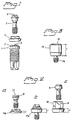
- Figure (1) illustrates a typical dental implant, and associated components by way of example.
- the head of the fixture (1) is provided with a hexagonal external feature (2), and a screw recess(3), which together allow the fixture to be manipulated, and permit the connection of an abutment (4), by means of an abutment screw (5).
- the head of the abutment screw may itself contain a recess (6) for a prosthesis retention screw.
- Figure (2) illustrates abutments of a type commonly used to support dental prostheses. Both abutment types are connected to the fixture by means of an abutment screw (7 and 8).
- One abutment type (9) is designed for cementation of a restoration onto a suitably shaped part (10), and another type, (11a and 11b) is designed for screw retention of the restoration by means of a "prosthetic" screw which is screwed through the restoration into an appropriate recess in the abutment screw head (12).
- the abutment length in each case is 1. Apart from differences in general shape, abutments of each type are available in different lengths, as illustrated (11a and 11b).
- the fixtures are usually placed as either a one stage surgical procedure, in which case the fixture, or an abutment connected to the fixture immediately protrudes through the skin or mucosa overlaying the site, or as a two stage procedure in which case the fixture is covered over with the overlaying tissue after installation (first stage surgery), and left to heal undisturbed for a period, at which time a second small surgical procedure, (second stage surgery) permits access to the head of the fixture, and an abutment, which protrudes through the tissue, is attached.
- tissue i.e. the gingivae for oral implants or skin for other fixtures
- an abutment of exactly the correct proportions may be predictably selected or prepared.
- healing abutments which are commonly formed of titanium, or a similary bio-compatible material, to the fixture, until the tissue has healed, and a relatively stable soft tissue contour has established.
- Healing abutments may be connected, either during one stage surgery, or at second stage surgery.
- FIG (3) illustrates a healing abutment, in which, a cylindrical body (13) tapers towards the fixture head, to which it is fixed by means of an integral abutment screw (14).
- a retentive feature (15) permits the healing abutment to be picked up and manipulated by a screw driver, and may permit the connection of various attachments.
- the length of the healing abutment (1) is selected to suit the height of the tissue collar around the fixture head.
- the healing abutment may be removed and the final abutment fitted.
- the impression is usually cast using an accurate material such as a dental model stone to create a model upon which the prostheses can be constructed. It is also common practice to use abutment replicas, which may be located within the matched impression coping so as to exactly replicate the important details of the abutment surface on the model.
- An impression may also be registered, using impression copings which fit the fixture head, and a model formed using fixture replicas which emulate the relevant detail of the fixture head, facilitating the production of an accurate working model.
- a prosthesis may be constructed which is fitted directly onto the fixture heads, or abutments may be selected or prepared out of the patients mouth and the prosthesis constructed on the working model with the abutments in place. This approach may be adapted so as to permit the position of the fixture heads to be registered upon completion of fixture installation.
- abutments may be selected, and prepared if necessary, and then provisional or definitive restorations or prostheses fabricated, ready for insertion, either at the time of second stage surgery or following healing of the gingivae or skin around the healing abutment after fixture installation and following stabilisation of the fixture.
- the system of interchangeable, abutment impression copings allows an accurate registration of the abutment, or healing abutment, and permits the direct substitution of each of the various impression copings within an index or impression, so as to apparantly transfer, the relations of, and or the component type, to a model adapted from an index or poured from an impression registered using the coping system.
- the lengths of the abutment change, which could cause problems with the building of the dental prostheses, bridges, etc., from strength and ethical point of view.
- the impression copings must also have an external shape which prevents rotation of the coping within the impression, and a component fitting surface that engages distinct features on the component.
- the present invention solves these problems in a facilitated manner and is characterized of the features mentioned in the characterising part of the following claim.
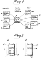
- Figure 4 shows an impression station with healing, abutment and level functions 16, and fixture head and level functions 17, and abutment level function 18.
- Figure 4 also shows a transfer, translate and transform station including coping and replica functions 19.
- Figure 4 also discloses a model station including revised abutment level function 20, revised abutment type function 21, and an abutment level function 22, and a fixture head level 23.
- Figure (5) illustrates an impression coping (24), height h , seated over an abutment, (25), length 1, where the total height of the coping ( h ) plus the abutment length ( l ) is equal to a standardised value.
- This standard value is equivalent to a fundamental height h f which is the height of an impression coping (26), with a recess at its base (27) which is designed to locate directly over a fixture head.
- h+1 h f
- a standardised retentive feature (28) situated at an identical location on each coping permits the coping to be retained by an appropriate impression material capable of flowing into the feature.
- each coping is identical in size and shape.
- the coping is smooth sided and uniform in cross-section; the width of the copings at any point is also standardised, and is no less then that of the largest component upon which it may be located.
- the component fitting surface of the copings may take many forms, which will permit the coping to precisely locate over an abutment or healing abutment, which may be located over the fixture head.
- the coping may be retained by friction or mechanical interlocking upon a retentive feature of the component, or by means of a retaining screw which passes through the coping, but maintains the standardised external dimensions and contour of the coping.
- FIG. (6) demonstrates how copings (IC) located on abutments (A) of different length ( l ) are selected such that the total height of the coping and abutment together is identical to that of a coping located on a fixture head (FH).
- Figure (7) demonstrates an impression coping (IC), which is fitted to a fixture head (FH) as well as impression copings of various lengths which have been pushed into place on the retentive features of the occlusal aspect of healing abutments (HA) of different lengths.
- the external dimensions of the coping/healing abutment combinations is analogous to that of the fixture head impression coping.
- an impression may be taken of e.g. the jaw, which will "pick up” the impression coping as the impression material flows into the retentive feature.
- the coping may then be removed from the impression, and replaced with an alternative coping, to which an appropriate replica may be attached which will lock into place in an identical fashion, replicating the orientation that would exist with alternative components connected to the fixture head, or replicating the orientation of the fixture head itself.
- impression copings In situations where the precise orientation of the external or internal anti-rotational features of a fixture must be established, the impression copings must also have an external shape which prevents rotation of the coping within the impression, and a component fitting surface that engages distinct features on the component.
- impression taking for the construction of a dental prosthesis as an example:
- Abutment replicas may then be located within the copings, and a working model formed, upon which restorations may be constructed. This process transfers the existing relations of the abutment from patient to model.
- the impression coping may be removed, and an abutment level impression coping of different type or length may be inserted in its place, and an appropriate abutment replica located within the coping.
- a working model may then be formed, which anticipates the replacement of the existing abutment with the planned abutment, thus minimising manipulation of components and the tissues. If necessary a fixture level coping may be placed, thus permitting preparation or selection of a new abutment on a laboratory model.
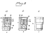
- the main body of the coping (29) is seated over the abutment (30).
- Opposing vertical slots, (31 and 32) of different heights, are located in the walls of the coping body.
- the outer casting of the coping (33) fits over the body of the coping.
- spurs (34) are located such that the outer casting may be located over the body in two different orientations, as depicted in Figure (8A and 8B).
- Figure (8A) shows the two part coping in place over a long abutment.
- the spurs (34) are located fully in the long slots (32), in the body of the coping.
- markings (35) on the exterior the coping body which are covered, or uncovered, depending on the state of extension of the casing, will tell the operator if the coping is correctly extended for use with the abutment in question.
- FIG. 8C There is also provided a fixture head coping, as depicted in Figure 8C.
- the external profile of this coping is essentially similar to that of the various different configurations of the two part coping and abutment or healing abutment combination; thus models may be constructed in a similar fashion to that described above.
Landscapes
- Health & Medical Sciences (AREA)
- Oral & Maxillofacial Surgery (AREA)
- Orthopedic Medicine & Surgery (AREA)
- Dentistry (AREA)
- Epidemiology (AREA)
- Life Sciences & Earth Sciences (AREA)
- Animal Behavior & Ethology (AREA)
- General Health & Medical Sciences (AREA)
- Public Health (AREA)
- Veterinary Medicine (AREA)
- Dental Prosthetics (AREA)
- Prostheses (AREA)
Abstract
Description
- Osseointegrated implants are fixtures commonly screwed into prepared sites in the jaw, facial, or limb bones for the retention of prostheses, e.g. dental bridges, facial prostheses, or limb prostheses. Such prostheses are usually retained by means of screws, adhesives, or mechanical attachments to an abutment, which is itself precisely located on and connected to the fixture by means of an abutment screw.
- An abutment is a trans-mucosal, or trans-dermal component, usually fabricated from a highly bio-compatible material capable of developing some kind of stable union with the adjacent living tissues, which facilitates the connection of the prosthesis to the fixture. Abutments may have a precise, prefabricated external configuration which will allow the use of prefabricated "prosthetic" components which precisely fit against the abutment for the fabrication of the prosthesis framework, or the abutment may be intended for preparation, in which case a framework may be constructed using conventional dental crown and bridge impression and fabrication techniques. Alternatively, a prosthesis may be fixed directly to the fixture head, using prefabricated "prosthetic" components which precisely fit against the fixture for the fabrication of the framework.
- Figure (1) illustrates a typical dental implant, and associated components by way of example. The head of the fixture (1) is provided with a hexagonal external feature (2), and a screw recess(3), which together allow the fixture to be manipulated, and permit the connection of an abutment (4), by means of an abutment screw (5). If the abutment is designed to allow screw retention of a prosthesis, the head of the abutment screw may itself contain a recess (6) for a prosthesis retention screw.
- Figure (2) illustrates abutments of a type commonly used to support dental prostheses. Both abutment types are connected to the fixture by means of an abutment screw (7 and 8). One abutment type (9) is designed for cementation of a restoration onto a suitably shaped part (10), and another type, (11a and 11b) is designed for screw retention of the restoration by means of a "prosthetic" screw which is screwed through the restoration into an appropriate recess in the abutment screw head (12). The abutment length in each case is 1. Apart from differences in general shape, abutments of each type are available in different lengths, as illustrated (11a and 11b).
- The fixtures are usually placed as either a one stage surgical procedure, in which case the fixture, or an abutment connected to the fixture immediately protrudes through the skin or mucosa overlaying the site, or as a two stage procedure in which case the fixture is covered over with the overlaying tissue after installation (first stage surgery), and left to heal undisturbed for a period, at which time a second small surgical procedure, (second stage surgery) permits access to the head of the fixture, and an abutment, which protrudes through the tissue, is attached.
- In areas of the mouth which are not cosmetically important, or in other situations where an abutment need not to be selected or prepared with precision, it is often possible to select or fit an abutment at the time of surgery, accepting that the final relationship of the abutments with the adjacent tissue may be less then ideal. There are other situations where an abutment may be placed, and subsequently replaced.
- However it is often more convenient to allow the tissues (i.e. the gingivae for oral implants or skin for other fixtures) to heal before selecting the definitive abutment to which the prosthesis will be attached, as it is only after the tissues have healed, that an abutment of exactly the correct proportions may be predictably selected or prepared.
- It is common practice to connect healing abutments, which are commonly formed of titanium, or a similary bio-compatible material, to the fixture, until the tissue has healed, and a relatively stable soft tissue contour has established. Healing abutments may be connected, either during one stage surgery, or at second stage surgery.
- Healing abutments, which often have a solid one piece construction, usually screw into the head of the fixture and act as a solid template against which the tissues can heal. Figure (3) illustrates a healing abutment, in which, a cylindrical body (13) tapers towards the fixture head, to which it is fixed by means of an integral abutment screw (14). A retentive feature (15) permits the healing abutment to be picked up and manipulated by a screw driver, and may permit the connection of various attachments. The length of the healing abutment (1) is selected to suit the height of the tissue collar around the fixture head. (some healing abutments have a two piece construction, in which case the healing abutment per se is positioned over the head of the fixture, and may interlock with any anti-rotational features of the fixture head, and a retaining screw may then be screwed through the abutment and into the head of the fixture).
- Once the tissues have healed and a stable tissue contour has established, and once a strong bony support for the fixture has developed, the healing abutment may be removed and the final abutment fitted.
- Once the final abutment has been fitted, it is common practice for an impression to be taken so as to construct a detailed model of the protruding abutment and the surrounding tissue. This usually involves the connection of precise, prefabricated impression copings to the abutments, and taking an impression which picks up the impression copings in such a way that the abutments may be precisely related to the surrounding tissues, and to one another.
- The impression is usually cast using an accurate material such as a dental model stone to create a model upon which the prostheses can be constructed. It is also common practice to use abutment replicas, which may be located within the matched impression coping so as to exactly replicate the important details of the abutment surface on the model.
- An impression may also be registered, using impression copings which fit the fixture head, and a model formed using fixture replicas which emulate the relevant detail of the fixture head, facilitating the production of an accurate working model. A prosthesis may be constructed which is fitted directly onto the fixture heads, or abutments may be selected or prepared out of the patients mouth and the prosthesis constructed on the working model with the abutments in place. This approach may be adapted so as to permit the position of the fixture heads to be registered upon completion of fixture installation. This means that abutments may be selected, and prepared if necessary, and then provisional or definitive restorations or prostheses fabricated, ready for insertion, either at the time of second stage surgery or following healing of the gingivae or skin around the healing abutment after fixture installation and following stabilisation of the fixture.
- It is important to note that research has demonstrated a form of tissue attachment to the commercially pure titanium surface of the tissue penetrating abutments, and this has been shown to be somewhat fragile, as manipulating and swapping over components seems to cause loss of tissue attachment, and possibly increases remodelling of the adjacent tissues.
- The system of interchangeable, abutment impression copings, for example healing abutment impression copings, allows an accurate registration of the abutment, or healing abutment, and permits the direct substitution of each of the various impression copings within an index or impression, so as to apparantly transfer, the relations of, and or the component type, to a model adapted from an index or poured from an impression registered using the coping system.
- It is referred to WO 97/17907 which mainly discloses systems according to the preamble of claim 1.
- It is known that the lengths of the abutment change, which could cause problems with the building of the dental prostheses, bridges, etc., from strength and ethical point of view. In situations where the precise orientation of the external or internal anti-rotational features of a fixture must be established, the impression copings must also have an external shape which prevents rotation of the coping within the impression, and a component fitting surface that engages distinct features on the component.
- The present invention solves these problems in a facilitated manner and is characterized of the features mentioned in the characterising part of the following claim.
- The invention according to claim 1 will now be described with reference to figure 1-7.
- Figures 1-3
- illustrate known implants and abutments,
- figure 4
- shows a system including impression-, transfer- and model features,
- figure 5
- illustrates the new impression coping,
- figure 6
- illustrates a second embodiment of the impression coping,
- figure 7
- illustrates a third embodiment of the impression coping, and
- figure 8
- illustrates a fourth embodiment of the impression coping.
- Figure 4 shows an impression station with healing, abutment and level functions 16, and fixture head and
level functions 17, andabutment level function 18. Figure 4 also shows a transfer, translate and transform station including coping andreplica functions 19. Figure 4 also discloses a model station including revisedabutment level function 20, revisedabutment type function 21, and anabutment level function 22, and afixture head level 23. - Figure (5) illustrates an impression coping (24), height h, seated over an abutment, (25), length 1, where the total height of the coping (h) plus the abutment length (l) is equal to a standardised value. This standard value is equivalent to a fundamental height hf which is the height of an impression coping (26), with a recess at its base (27) which is designed to locate directly over a fixture head.
Thus: h+1= h f
In all cases, a standardised retentive feature (28) situated at an identical location on each coping, permits the coping to be retained by an appropriate impression material capable of flowing into the feature. Above the retentive feature each coping is identical in size and shape. Below the retentive feature the coping is smooth sided and uniform in cross-section; the width of the copings at any point is also standardised, and is no less then that of the largest component upon which it may be located. - The component fitting surface of the copings may take many forms, which will permit the coping to precisely locate over an abutment or healing abutment, which may be located over the fixture head. The coping may be retained by friction or mechanical interlocking upon a retentive feature of the component, or by means of a retaining screw which passes through the coping, but maintains the standardised external dimensions and contour of the coping.
- Apart from accommodating prefabricated abutments of different purpose and design, copings are provided of different heights, so as to accommodate abutments of different lengths, such that if the length of the abutment is increased, then the height of the coping is reduced accordingly. Figure (6) demonstrates how copings (IC) located on abutments (A) of different length (l) are selected such that the total height of the coping and abutment together is identical to that of a coping located on a fixture head (FH).
- This principal is also applied to healing abutments. Figure (7) demonstrates an impression coping (IC), which is fitted to a fixture head (FH) as well as impression copings of various lengths which have been pushed into place on the retentive features of the occlusal aspect of healing abutments (HA) of different lengths. The external dimensions of the coping/healing abutment combinations is analogous to that of the fixture head impression coping.
- With an impression coping of the correct height seated in place over a prefabricated component located on the fixture head, an impression may be taken of e.g. the jaw, which will "pick up" the impression coping as the impression material flows into the retentive feature. The coping may then be removed from the impression, and replaced with an alternative coping, to which an appropriate replica may be attached which will lock into place in an identical fashion, replicating the orientation that would exist with alternative components connected to the fixture head, or replicating the orientation of the fixture head itself.
- In situations where the precise orientation of the external or internal anti-rotational features of a fixture must be established, the impression copings must also have an external shape which prevents rotation of the coping within the impression, and a component fitting surface that engages distinct features on the component. Use of the system is now described by way of example, using impression taking for the construction of a dental prosthesis as an example:
- 1. Fixture head impression copings may be attached to the fixture head immediately upon installation, or at any later date, and an impression or alternative form of index or registration taken.
Fixture head replicas may then be located within the coping, and a working model created, upon which abutments may be prepared or attached, and restorations may be constructed. This process transfers the relations of the fixture head from patient to model.
Alternatively, the impression coping may be removed, and an abutment level impression coping of particular type or length may be inserted in its place, and an appropriate abutment replica located within the coping. A working model may then be formed, which anticipates the connection of the planned abutments to the fixture heads, thus permitting preliminary stages of the construction of the restoration, or even a final restoration to be constructed, without having to handle the actual abutments in the laboratory. This process transforms and translates the relations of the fixture head in the jaw to a model which accurately demonstrates the relations that the selected abutment type would have if located onto the fixture head. - 2. Healing abutment impression copings may be located on the occlusal aspect of Healing Abutments which have been connected to the fixture head either immediately upon installation of the fixture, or at the time of second stage surgery, (or subsequently). An impression or alternative form of index or registration may be taken once the soft tissues have been closed around the abutment at the time of surgery, or ideally after a period of healing and tissue maturation.
The healing abutment impression coping may then be removed from the impression, and an Abutment level or Fixture head level impression coping of particular type or length may be inserted in its place, an an appropriate replica located within the coping. A working model may then be formed, which anticipates the connection of a planned abutment to the fixture head, or replicates the position of the fixture head itself. This process thus transforms and translates the relations of the healing abutment, fixture head, jaw, and adjacent soft tissue to a model which accurately demonstrates the relations of the fixture head, or the relations that the selected abutment type would have if located onto the fixture head.
If the tissues have been allowed to heal and mature following surgery, the final abutments may be predictably selected or prepared in the knowledge that there will be little further change in tissue contour, thus facilitating, and increasing the predictability of subsequent restorative stages. - 3. Abutment impression copings may be located on the abutments and an impression or alternative form of index or registration taken which will pick up the impression copings.
- Abutment replicas may then be located within the copings, and a working model formed, upon which restorations may be constructed. This process transfers the existing relations of the abutment from patient to model. Alternatively, if there is a need to change abutments, e.g. after shrinking of the soft tissues, the impression coping may be removed, and an abutment level impression coping of different type or length may be inserted in its place, and an appropriate abutment replica located within the coping. A working model may then be formed, which anticipates the replacement of the existing abutment with the planned abutment, thus minimising manipulation of components and the tissues. If necessary a fixture level coping may be placed, thus permitting preparation or selection of a new abutment on a laboratory model.
- For an implant system comprising of many different fixture and abutment types and sizes many copings of the type described above will be required. A further embodiment of this invention is intended to overcame this potential drawback.
- This alternative embodiment will now be described with reference to Figure (8), in which a two part impression coping is seated over abutments of different lengths.
- The main body of the coping (29) is seated over the abutment (30). Opposing vertical slots, (31 and 32) of different heights, are located in the walls of the coping body. The outer casting of the coping (33), fits over the body of the coping. On the inner aspect of the casing (33), spurs (34) are located such that the outer casting may be located over the body in two different orientations, as depicted in Figure (8A and 8B).
- Figure (8A), shows the two part coping in place over a long abutment. In this case, the spurs (34) are located fully in the long slots (32), in the body of the coping.
- To convert the coping for use with a short abutment the two parts of the coping, (29 and 33) are pulled slightly apart so that the spurs (34) disengage the slots (35). The body (29) may then be rotated within the casing (33), such that the spurs (34) may be inserted into the short slots (31), thus lengthening the total height of the coping, as in Figure 8B. Different abutment heights may be catered for by varying the length and number of slots in the body of the coping.
- To facilitate the use of the coping, markings (35) on the exterior the coping body, which are covered, or uncovered, depending on the state of extension of the casing, will tell the operator if the coping is correctly extended for use with the abutment in question.
- There is also provided a fixture head coping, as depicted in Figure 8C. This is the fundamental coping for the system, as described elsewhere in this text. The external profile of this coping is essentially similar to that of the various different configurations of the two part coping and abutment or healing abutment combination; thus models may be constructed in a similar fashion to that described above.
Claims (1)
- A system of interchangeable impression copings (24, 26) together with abutments (25), for use with osseointegrated implants (1) which will allow an accurate registration of the fixture head, abutment, healing abutment, or other prefabricated components to which the implant may be connected, and permits the direct substitution of each of the various impression copings within an index or impression, so as to transfer, translate, or transform the relations and or the type of component to a model adapted from an index or poured from an impression registered using the coping system,
the impression copings (24, 26) having a component fitting surface with a form and width which permits the coping to precisely locate over a fixture head, abutment, healing abutment or other prefabricated components, and a height (h), the abutments (25) having outer contours fitting to the copings and the fixture heads, and a length (l),
characterised in that the height (h) of the copings (24, 26) vary in dependence of the length (l) of the abutments, such that the total height (hf) of the coping (24, 26) with the abutment (25), is equal to a standardised value.
Applications Claiming Priority (5)
| Application Number | Priority Date | Filing Date | Title |
|---|---|---|---|
| GB9715793 | 1997-07-25 | ||
| GBGB9715793.7A GB9715793D0 (en) | 1997-07-25 | 1997-07-25 | An impression coping system for osseointegrated implants |
| GBGB9719508.5A GB9719508D0 (en) | 1997-07-25 | 1997-09-12 | Modified impression coping system for osseointergrated implants |
| GB9719508 | 1997-09-12 | ||
| PCT/SE1998/001344 WO1999004723A1 (en) | 1997-07-25 | 1998-07-08 | An impression coping system for osseointegrated implants |
Publications (2)
| Publication Number | Publication Date |
|---|---|
| EP0998241A1 EP0998241A1 (en) | 2000-05-10 |
| EP0998241B1 true EP0998241B1 (en) | 2006-04-05 |
Family
ID=26311946
Family Applications (1)
| Application Number | Title | Priority Date | Filing Date |
|---|---|---|---|
| EP98934058A Expired - Lifetime EP0998241B1 (en) | 1997-07-25 | 1998-07-08 | An impression coping system for osseointegrated implants |
Country Status (8)
| Country | Link |
|---|---|
| US (1) | US6305939B1 (en) |
| EP (1) | EP0998241B1 (en) |
| JP (1) | JP2001510705A (en) |
| AT (1) | ATE322223T1 (en) |
| AU (1) | AU739477B2 (en) |
| CA (1) | CA2296418C (en) |
| DE (1) | DE69834115T2 (en) |
| WO (1) | WO1999004723A1 (en) |
Families Citing this family (43)
| Publication number | Priority date | Publication date | Assignee | Title |
|---|---|---|---|---|
| SE522958C2 (en) | 2000-12-29 | 2004-03-16 | Nobel Biocare Ab | Procedure, arrangement (device) and programs at or for prosthetic installation |
| US6406295B1 (en) * | 2001-07-13 | 2002-06-18 | Brian A. Mahler | Identification of dental implant components |
| US6824386B2 (en) | 2001-11-01 | 2004-11-30 | Astra Tech Ab | Components for improved impression making |
| SE520765C2 (en) * | 2001-12-28 | 2003-08-19 | Nobel Biocare Ab | Device and arrangement for inserting holes for bone implants by means of template, preferably jawbones |
| GB0213774D0 (en) * | 2002-06-15 | 2002-07-24 | Osseobiotek Ltd | Prosthesis |
| IL158789A (en) | 2002-11-13 | 2009-11-18 | Biomet 3I Llc | Dental implant system |
| SE526666C2 (en) * | 2002-12-30 | 2005-10-25 | Nobel Biocare Ab | Device and arrangement for fixture installation |
| SE526665C2 (en) * | 2002-12-30 | 2005-10-25 | Nobel Biocare Ab | Device for dental screw-in arrangement |
| SE526223C2 (en) * | 2003-12-10 | 2005-08-02 | Nobel Biocare Ab | System and apparatus for the manufacture and insertion of dental bridge construction |
| SE527503C2 (en) * | 2004-08-05 | 2006-03-21 | Nobel Biocare Ab | Device and method for facilitating application to correct position of tooth or tooth residue template |
| US7322824B2 (en) * | 2004-08-17 | 2008-01-29 | Schmitt Stephen M | Design and manufacture of dental implant restorations |
| ES2845610T3 (en) | 2005-06-30 | 2021-07-27 | Biomet 3I Llc | Method for manufacturing dental implant components |
| US11219511B2 (en) | 2005-10-24 | 2022-01-11 | Biomet 3I, Llc | Methods for placing an implant analog in a physical model of the patient's mouth |
| US8257083B2 (en) * | 2005-10-24 | 2012-09-04 | Biomet 3I, Llc | Methods for placing an implant analog in a physical model of the patient's mouth |
| US8043091B2 (en) * | 2006-02-15 | 2011-10-25 | Voxelogix Corporation | Computer machined dental tooth system and method |
| US8366442B2 (en) * | 2006-02-15 | 2013-02-05 | Bankruptcy Estate Of Voxelogix Corporation | Dental apparatus for radiographic and non-radiographic imaging |
| AU2007248943B2 (en) | 2006-05-04 | 2013-05-23 | Nobel Biocare Services Ag | A device for securing a dental implant in bone tissue, a method for making a surgical template and a method of securing a dental implant in bone tissue |
| KR100677870B1 (en) * | 2006-05-29 | 2007-02-02 | 주식회사 메가젠 | Healing abutment and dental implant having the same |
| WO2008030965A2 (en) * | 2006-09-06 | 2008-03-13 | Voxelogix Corporation | Methods for the virtual design and computer manufacture of intra oral devices |
| US7835811B2 (en) * | 2006-10-07 | 2010-11-16 | Voxelogix Corporation | Surgical guides and methods for positioning artificial teeth and dental implants |
| AU2007343330B2 (en) | 2007-01-10 | 2013-08-01 | Nobel Biocare Services Ag | Method and system for dental planning and production |
| US20080228303A1 (en) * | 2007-03-13 | 2008-09-18 | Schmitt Stephen M | Direct manufacture of dental and medical devices |
| US8454363B2 (en) | 2008-11-06 | 2013-06-04 | William B. Worthington | Dental implant system |
| US20100159417A1 (en) * | 2008-12-18 | 2010-06-24 | Dale Whipple | Dental impression cap with engagement feature |
| EP2254068B1 (en) | 2009-05-18 | 2020-08-19 | Nobel Biocare Services AG | Method and system providing improved data matching for virtual planning |
| US8867800B2 (en) * | 2009-05-27 | 2014-10-21 | James R. Glidewell Dental Ceramics, Inc. | Method of designing and fabricating patient-specific restorations from intra-oral scanning of a digital impression |
| US8348669B1 (en) | 2009-11-04 | 2013-01-08 | Bankruptcy Estate Of Voxelogix Corporation | Surgical template and method for positioning dental casts and dental implants |
| US20120052463A1 (en) * | 2010-08-24 | 2012-03-01 | Alan Pollet | Device and Method for Capturing Dental Records |
| EP3777760B1 (en) | 2011-05-16 | 2024-06-19 | Biomet 3I, LLC | Temporary abutment cap with informational markers |
| US9925024B2 (en) | 2011-06-28 | 2018-03-27 | Biomet 3I, Llc | Dental implant and abutment tools |
| US9089382B2 (en) | 2012-01-23 | 2015-07-28 | Biomet 3I, Llc | Method and apparatus for recording spatial gingival soft tissue relationship to implant placement within alveolar bone for immediate-implant placement |
| US9452032B2 (en) | 2012-01-23 | 2016-09-27 | Biomet 3I, Llc | Soft tissue preservation temporary (shell) immediate-implant abutment with biological active surface |
| GB201212125D0 (en) * | 2012-07-09 | 2012-08-22 | Nobel Biocare Services Ag | Abutment system and dental methods |
| US20140080092A1 (en) | 2012-09-14 | 2014-03-20 | Biomet 3I, Llc | Temporary dental prosthesis for use in developing final dental prosthesis |
| US8905757B2 (en) | 2012-12-03 | 2014-12-09 | E. Kats Enterprises Ltd. | Method and apparatus for measuring a location and orientation of a plurality of implants |
| US8926328B2 (en) | 2012-12-27 | 2015-01-06 | Biomet 3I, Llc | Jigs for placing dental implant analogs in models and methods of doing the same |
| US9687327B2 (en) * | 2013-03-14 | 2017-06-27 | Anthony Prestipino | Apparatuses and methods for making a final hybrid prosthesis to be attached to dental implants |
| WO2015094699A1 (en) | 2013-12-20 | 2015-06-25 | Biomet 3I, Llc | Dental system for developing custom prostheses through scanning of coded members |
| DE102014001389A1 (en) * | 2014-01-29 | 2015-08-13 | Celgen Ag | Distraction membrane with protective cap |
| US9700390B2 (en) | 2014-08-22 | 2017-07-11 | Biomet 3I, Llc | Soft-tissue preservation arrangement and method |
| WO2016144970A1 (en) | 2015-03-09 | 2016-09-15 | Chu Stephen J | Gingival ovate pontic and methods of using the same |
| IL248179A0 (en) | 2016-10-05 | 2017-01-31 | Mis Implants Tech Ltd | Scan post, bite pillar, and related method for recording dental implant position |
| IT201800009288A1 (en) * | 2018-10-09 | 2020-04-09 | Ennio Calabria | DENTAL IMPLANT SYSTEM |
Family Cites Families (19)
| Publication number | Priority date | Publication date | Assignee | Title |
|---|---|---|---|---|
| SE455371C (en) * | 1987-04-22 | 1990-03-26 | Astra Meditec Ab | DEVICE FOR FIXING A DENTAL PROTEIN |
| US4850870C1 (en) | 1987-10-23 | 2001-07-24 | Implant Innovations Inc | Prosthodontic restoration components |
| US4955811A (en) | 1988-06-23 | 1990-09-11 | Implant Innovations, Inc. | Non-rotational single-tooth prosthodontic restoration |
| SE464959B (en) * | 1990-01-18 | 1991-07-08 | Nobelpharma Ab | PRINT STOP MADE IN ELASTIC MATERIAL |
| US5334024A (en) * | 1990-03-21 | 1994-08-02 | Core-Vent Corporation | Transfer abutment |
| US5350297A (en) | 1991-12-24 | 1994-09-27 | Cohen Robert N | Method and apparatus for recording the position of dental implants |
| US5213502A (en) * | 1992-06-10 | 1993-05-25 | Fereidoun Daftary | Interlockable two-piece impression coping for anatomical dental abutment restorative systems |
| US5662476A (en) | 1992-06-29 | 1997-09-02 | Nobel Biocare Ab | Prosthetic implant restoration method |
| US5527182A (en) | 1993-12-23 | 1996-06-18 | Adt Advanced Dental Technologies, Ltd. | Implant abutment systems, devices, and techniques |
| US5755574A (en) * | 1994-04-21 | 1998-05-26 | D'alise; James V. | Endosseous dental implant and method of manufacture |
| DE4415670A1 (en) * | 1994-05-04 | 1995-11-09 | Degussa | Impression cap for dental implants |
| US5685715A (en) * | 1995-03-10 | 1997-11-11 | Beaty; Keith D. | Self-indexing transfer impression coping |
| US5938443A (en) | 1994-11-08 | 1999-08-17 | Implant Innovations, Inc. | Impression coping for use in an open tray and closed tray impression methodology |
| US5658147A (en) * | 1995-09-19 | 1997-08-19 | Shopvest, Inc. | Working model for prosthodontic preparation of a crown for installation on an implant fixture |
| US5904483A (en) | 1995-11-17 | 1999-05-18 | Wade; Curtis K. | Dental implant systems and methods |
| US5674073A (en) * | 1996-01-30 | 1997-10-07 | Nobel Biocare Ab | Impression coping |
| ATE185060T1 (en) * | 1996-02-08 | 1999-10-15 | Straumann Inst Ag | IMPRESSION SYSTEM FOR AN IMPLANT CLOSURE PROJECTING FROM THE HUMAN TISSUE STRUCTURE |
| AU1435597A (en) | 1996-02-08 | 1997-08-28 | Institut Straumann Ag | Impression system for implants with an impression cap |
| US5759036A (en) * | 1996-07-29 | 1998-06-02 | Hinds; Kenneth F. | Complete dental implant system and method |
-
1998
- 1998-07-08 AT AT98934058T patent/ATE322223T1/en not_active IP Right Cessation
- 1998-07-08 EP EP98934058A patent/EP0998241B1/en not_active Expired - Lifetime
- 1998-07-08 WO PCT/SE1998/001344 patent/WO1999004723A1/en active IP Right Grant
- 1998-07-08 AU AU83662/98A patent/AU739477B2/en not_active Ceased
- 1998-07-08 JP JP2000503788A patent/JP2001510705A/en active Pending
- 1998-07-08 US US09/463,185 patent/US6305939B1/en not_active Expired - Lifetime
- 1998-07-08 CA CA002296418A patent/CA2296418C/en not_active Expired - Fee Related
- 1998-07-08 DE DE69834115T patent/DE69834115T2/en not_active Expired - Lifetime
Also Published As
| Publication number | Publication date |
|---|---|
| DE69834115T2 (en) | 2006-10-26 |
| EP0998241A1 (en) | 2000-05-10 |
| JP2001510705A (en) | 2001-08-07 |
| CA2296418A1 (en) | 1999-02-04 |
| AU739477B2 (en) | 2001-10-11 |
| ATE322223T1 (en) | 2006-04-15 |
| CA2296418C (en) | 2007-08-28 |
| US6305939B1 (en) | 2001-10-23 |
| WO1999004723A1 (en) | 1999-02-04 |
| DE69834115D1 (en) | 2006-05-18 |
| AU8366298A (en) | 1999-02-16 |
Similar Documents
| Publication | Publication Date | Title |
|---|---|---|
| EP0998241B1 (en) | An impression coping system for osseointegrated implants | |
| RU2290127C2 (en) | Components and method of improved production of imprint | |
| CA2196397C (en) | Impression coping | |
| US5106300A (en) | Dental implant attachment structure and method | |
| US6290500B1 (en) | Dental implant system and method | |
| EP0879023B1 (en) | Emergence profile system having a combined healing abutment and impression coping | |
| US5350297A (en) | Method and apparatus for recording the position of dental implants | |
| US6283752B1 (en) | Universal impression coping system | |
| EP1651132B1 (en) | Kit for preparing a dental abutment | |
| US6325628B1 (en) | Temporary implant components, system and method | |
| US20100040996A1 (en) | Method for manufacturing a prosthesis made prior to implant placement | |
| US20020039718A1 (en) | Dental implant system and additional methods of attachment | |
| US20050136378A1 (en) | Implant system and method of installation thereof | |
| PL182766B1 (en) | Dental surgery set and process for making dental prostheses | |
| US20190247149A1 (en) | Custom dental component and scan body | |
| Misch et al. | Generic terminology for endosseous implant prosthodontics | |
| Hiochwald | Surgical template impression during stage I surgery for fabrication of a provisional restoration to be placed at stage II surgery | |
| US20030044749A1 (en) | Stable dental analog systems | |
| Lewis | An esthetic titanium abutment: report of a technique. | |
| Sicilia et al. | Evaluation of the precision obtained with a fixed surgical template in the placement of implants for rehabilitation of the completely edentulous maxilla: a clinical report. | |
| Reiser et al. | Initiating Restorative Procedures at the First-Stage Implant Surgery With a Positional Index: A Case Report. | |
| Davidoff | Late stage soft tissue modification for anatomically correct implant-supported restorations | |
| Garfield | Implant prostheses for convertibility, stress control, esthetics, and hygiene | |
| Judy | The abutment seating jig: a prosthodontic implant adjunct | |
| IL173202A (en) | Method and kit for preparing a dental abutment |
Legal Events
| Date | Code | Title | Description |
|---|---|---|---|
| PUAI | Public reference made under article 153(3) epc to a published international application that has entered the european phase |
Free format text: ORIGINAL CODE: 0009012 |
|
| 17P | Request for examination filed |
Effective date: 20000225 |
|
| AK | Designated contracting states |
Kind code of ref document: A1 Designated state(s): AT BE CH DE DK ES FR GB GR IT LI NL SE |
|
| 17Q | First examination report despatched |
Effective date: 20030405 |
|
| GRAP | Despatch of communication of intention to grant a patent |
Free format text: ORIGINAL CODE: EPIDOSNIGR1 |
|
| GRAS | Grant fee paid |
Free format text: ORIGINAL CODE: EPIDOSNIGR3 |
|
| GRAA | (expected) grant |
Free format text: ORIGINAL CODE: 0009210 |
|
| AK | Designated contracting states |
Kind code of ref document: B1 Designated state(s): AT BE CH DE DK ES FR GB GR IT LI NL SE |
|
| PG25 | Lapsed in a contracting state [announced via postgrant information from national office to epo] |
Ref country code: NL Free format text: LAPSE BECAUSE OF FAILURE TO SUBMIT A TRANSLATION OF THE DESCRIPTION OR TO PAY THE FEE WITHIN THE PRESCRIBED TIME-LIMIT Effective date: 20060405 Ref country code: IT Free format text: LAPSE BECAUSE OF FAILURE TO SUBMIT A TRANSLATION OF THE DESCRIPTION OR TO PAY THE FEE WITHIN THE PRESCRIBED TIME-LIMIT;WARNING: LAPSES OF ITALIAN PATENTS WITH EFFECTIVE DATE BEFORE 2007 MAY HAVE OCCURRED AT ANY TIME BEFORE 2007. THE CORRECT EFFECTIVE DATE MAY BE DIFFERENT FROM THE ONE RECORDED. Effective date: 20060405 Ref country code: AT Free format text: LAPSE BECAUSE OF FAILURE TO SUBMIT A TRANSLATION OF THE DESCRIPTION OR TO PAY THE FEE WITHIN THE PRESCRIBED TIME-LIMIT Effective date: 20060405 |
|
| REG | Reference to a national code |
Ref country code: GB Ref legal event code: FG4D |
|
| REG | Reference to a national code |
Ref country code: CH Ref legal event code: EP |
|
| REF | Corresponds to: |
Ref document number: 69834115 Country of ref document: DE Date of ref document: 20060518 Kind code of ref document: P |
|
| REG | Reference to a national code |
Ref country code: CH Ref legal event code: NV Representative=s name: E. BLUM & CO. PATENTANWAELTE |
|
| PG25 | Lapsed in a contracting state [announced via postgrant information from national office to epo] |
Ref country code: SE Free format text: LAPSE BECAUSE OF FAILURE TO SUBMIT A TRANSLATION OF THE DESCRIPTION OR TO PAY THE FEE WITHIN THE PRESCRIBED TIME-LIMIT Effective date: 20060705 Ref country code: DK Free format text: LAPSE BECAUSE OF FAILURE TO SUBMIT A TRANSLATION OF THE DESCRIPTION OR TO PAY THE FEE WITHIN THE PRESCRIBED TIME-LIMIT Effective date: 20060705 |
|
| PG25 | Lapsed in a contracting state [announced via postgrant information from national office to epo] |
Ref country code: ES Free format text: LAPSE BECAUSE OF FAILURE TO SUBMIT A TRANSLATION OF THE DESCRIPTION OR TO PAY THE FEE WITHIN THE PRESCRIBED TIME-LIMIT Effective date: 20060716 |
|
| ET | Fr: translation filed | ||
| NLV1 | Nl: lapsed or annulled due to failure to fulfill the requirements of art. 29p and 29m of the patents act | ||
| PLBE | No opposition filed within time limit |
Free format text: ORIGINAL CODE: 0009261 |
|
| STAA | Information on the status of an ep patent application or granted ep patent |
Free format text: STATUS: NO OPPOSITION FILED WITHIN TIME LIMIT |
|
| 26N | No opposition filed |
Effective date: 20070108 |
|
| REG | Reference to a national code |
Ref country code: CH Ref legal event code: PFA Owner name: NOBEL BIOCARE AB (PUBL) Free format text: NOBEL BIOCARE AB (PUBL)#BOX 5190#402 26 GOETEBORG (SE) -TRANSFER TO- NOBEL BIOCARE AB (PUBL)#BOX 5190#402 26 GOETEBORG (SE) |
|
| PG25 | Lapsed in a contracting state [announced via postgrant information from national office to epo] |
Ref country code: GR Free format text: LAPSE BECAUSE OF FAILURE TO SUBMIT A TRANSLATION OF THE DESCRIPTION OR TO PAY THE FEE WITHIN THE PRESCRIBED TIME-LIMIT Effective date: 20060706 |
|
| PGFP | Annual fee paid to national office [announced via postgrant information from national office to epo] |
Ref country code: BE Payment date: 20110525 Year of fee payment: 14 |
|
| REG | Reference to a national code |
Ref country code: CH Ref legal event code: PUE Owner name: NOBEL BIOCARE SERVICES AG Free format text: NOBEL BIOCARE AB (PUBL)#BOX 5190#402 26 GOETEBORG (SE) -TRANSFER TO- NOBEL BIOCARE SERVICES AG#POSTFACH#8058 ZUERICH-FLUGHAFEN (CH) |
|
| REG | Reference to a national code |
Ref country code: FR Ref legal event code: TP Owner name: NOBEL BIOCARE SERVICES AG, CH Effective date: 20111007 |
|
| REG | Reference to a national code |
Ref country code: DE Ref legal event code: R082 Ref document number: 69834115 Country of ref document: DE Representative=s name: GLAWE, DELFS, MOLL, PATENTANWAELTE, DE |
|
| REG | Reference to a national code |
Ref country code: DE Ref legal event code: R082 Ref document number: 69834115 Country of ref document: DE Representative=s name: GLAWE DELFS MOLL PARTNERSCHAFT MBB VON PATENT-, DE Effective date: 20120227 Ref country code: DE Ref legal event code: R081 Ref document number: 69834115 Country of ref document: DE Owner name: NOBEL BIOCARE SERVICES AG, CH Free format text: FORMER OWNER: NOBEL BIOCARE AB (PUBL), GOETEBURG/GOETEBORG, SE Effective date: 20120227 |
|
| REG | Reference to a national code |
Ref country code: GB Ref legal event code: 732E Free format text: REGISTERED BETWEEN 20120419 AND 20120425 |
|
| BERE | Be: lapsed |
Owner name: NOBEL BIOCARE SERVICE A.G. Effective date: 20120731 |
|
| PG25 | Lapsed in a contracting state [announced via postgrant information from national office to epo] |
Ref country code: BE Free format text: LAPSE BECAUSE OF NON-PAYMENT OF DUE FEES Effective date: 20120731 |
|
| PGFP | Annual fee paid to national office [announced via postgrant information from national office to epo] |
Ref country code: CH Payment date: 20140625 Year of fee payment: 17 |
|
| PGFP | Annual fee paid to national office [announced via postgrant information from national office to epo] |
Ref country code: DE Payment date: 20140610 Year of fee payment: 17 |
|
| PGFP | Annual fee paid to national office [announced via postgrant information from national office to epo] |
Ref country code: FR Payment date: 20140609 Year of fee payment: 17 Ref country code: GB Payment date: 20140630 Year of fee payment: 17 |
|
| REG | Reference to a national code |
Ref country code: DE Ref legal event code: R119 Ref document number: 69834115 Country of ref document: DE |
|
| REG | Reference to a national code |
Ref country code: CH Ref legal event code: PL |
|
| GBPC | Gb: european patent ceased through non-payment of renewal fee |
Effective date: 20150708 |
|
| PG25 | Lapsed in a contracting state [announced via postgrant information from national office to epo] |
Ref country code: DE Free format text: LAPSE BECAUSE OF NON-PAYMENT OF DUE FEES Effective date: 20160202 Ref country code: GB Free format text: LAPSE BECAUSE OF NON-PAYMENT OF DUE FEES Effective date: 20150708 Ref country code: LI Free format text: LAPSE BECAUSE OF NON-PAYMENT OF DUE FEES Effective date: 20150731 Ref country code: CH Free format text: LAPSE BECAUSE OF NON-PAYMENT OF DUE FEES Effective date: 20150731 |
|
| REG | Reference to a national code |
Ref country code: FR Ref legal event code: ST Effective date: 20160331 |
|
| PG25 | Lapsed in a contracting state [announced via postgrant information from national office to epo] |
Ref country code: FR Free format text: LAPSE BECAUSE OF NON-PAYMENT OF DUE FEES Effective date: 20150731 |