EP0997620A2 - Cylinder for stratified scavenging two-cycle engine - Google Patents
Cylinder for stratified scavenging two-cycle engine Download PDFInfo
- Publication number
- EP0997620A2 EP0997620A2 EP99100729A EP99100729A EP0997620A2 EP 0997620 A2 EP0997620 A2 EP 0997620A2 EP 99100729 A EP99100729 A EP 99100729A EP 99100729 A EP99100729 A EP 99100729A EP 0997620 A2 EP0997620 A2 EP 0997620A2
- Authority
- EP
- European Patent Office
- Prior art keywords
- cylinder
- scavenging
- flow passage
- opening portion
- horizontal
- Prior art date
- Legal status (The legal status is an assumption and is not a legal conclusion. Google has not performed a legal analysis and makes no representation as to the accuracy of the status listed.)
- Granted
Links
Images


Classifications
-
- F—MECHANICAL ENGINEERING; LIGHTING; HEATING; WEAPONS; BLASTING
- F02—COMBUSTION ENGINES; HOT-GAS OR COMBUSTION-PRODUCT ENGINE PLANTS
- F02B—INTERNAL-COMBUSTION PISTON ENGINES; COMBUSTION ENGINES IN GENERAL
- F02B29/00—Engines characterised by provision for charging or scavenging not provided for in groups F02B25/00, F02B27/00 or F02B33/00 - F02B39/00; Details thereof
-
- F—MECHANICAL ENGINEERING; LIGHTING; HEATING; WEAPONS; BLASTING
- F02—COMBUSTION ENGINES; HOT-GAS OR COMBUSTION-PRODUCT ENGINE PLANTS
- F02B—INTERNAL-COMBUSTION PISTON ENGINES; COMBUSTION ENGINES IN GENERAL
- F02B25/00—Engines characterised by using fresh charge for scavenging cylinders
- F02B25/14—Engines characterised by using fresh charge for scavenging cylinders using reverse-flow scavenging, e.g. with both outlet and inlet ports arranged near bottom of piston stroke
-
- F—MECHANICAL ENGINEERING; LIGHTING; HEATING; WEAPONS; BLASTING
- F02—COMBUSTION ENGINES; HOT-GAS OR COMBUSTION-PRODUCT ENGINE PLANTS
- F02F—CYLINDERS, PISTONS OR CASINGS, FOR COMBUSTION ENGINES; ARRANGEMENTS OF SEALINGS IN COMBUSTION ENGINES
- F02F1/00—Cylinders; Cylinder heads
-
- F—MECHANICAL ENGINEERING; LIGHTING; HEATING; WEAPONS; BLASTING
- F02—COMBUSTION ENGINES; HOT-GAS OR COMBUSTION-PRODUCT ENGINE PLANTS
- F02F—CYLINDERS, PISTONS OR CASINGS, FOR COMBUSTION ENGINES; ARRANGEMENTS OF SEALINGS IN COMBUSTION ENGINES
- F02F1/00—Cylinders; Cylinder heads
- F02F1/18—Other cylinders
- F02F1/22—Other cylinders characterised by having ports in cylinder wall for scavenging or charging
-
- F—MECHANICAL ENGINEERING; LIGHTING; HEATING; WEAPONS; BLASTING
- F02—COMBUSTION ENGINES; HOT-GAS OR COMBUSTION-PRODUCT ENGINE PLANTS
- F02B—INTERNAL-COMBUSTION PISTON ENGINES; COMBUSTION ENGINES IN GENERAL
- F02B75/00—Other engines
- F02B75/02—Engines characterised by their cycles, e.g. six-stroke
- F02B2075/022—Engines characterised by their cycles, e.g. six-stroke having less than six strokes per cycle
- F02B2075/025—Engines characterised by their cycles, e.g. six-stroke having less than six strokes per cycle two
-
- Y—GENERAL TAGGING OF NEW TECHNOLOGICAL DEVELOPMENTS; GENERAL TAGGING OF CROSS-SECTIONAL TECHNOLOGIES SPANNING OVER SEVERAL SECTIONS OF THE IPC; TECHNICAL SUBJECTS COVERED BY FORMER USPC CROSS-REFERENCE ART COLLECTIONS [XRACs] AND DIGESTS
- Y02—TECHNOLOGIES OR APPLICATIONS FOR MITIGATION OR ADAPTATION AGAINST CLIMATE CHANGE
- Y02T—CLIMATE CHANGE MITIGATION TECHNOLOGIES RELATED TO TRANSPORTATION
- Y02T10/00—Road transport of goods or passengers
- Y02T10/10—Internal combustion engine [ICE] based vehicles
- Y02T10/12—Improving ICE efficiencies
Definitions
- the present invention relates to a cylinder for a stratified scavenging two-cycle engine, and more particularly to a scavenging flow passage of the cylinder.
- a cylinder liner is set within a cylinder portion forming space which is formed in the inside with a plurality of die casting dies.
- a scavenging passage horizontal portion penetrating to the outside of the cylinder and a scavenging passage vertical portion are formed with the die casting dies, and molten metal is poured into them. After the molten metal is solidified, the die casting dies are removed, and a blank cap is inserted into a portion of the scavenging passage horizontal portion penetrating in the outside to form a scavenging passage.
- the cylinder liner is used for the cylinder portion formed by the plurality of die casting dies.
- a die casting die protruding portion is formed in such a manner to form the scavenging passage horizontal portion penetrating to the outside of the cylinder with the die casting die. After casting, the die casting die protruding portion is pulled out, and the blank cap is inserted into the formed scavenging passage horizontal portion to form the scavenging passage.
- the number of used parts such as the cylinder liner, die casting die protruding portion, blank cap, and the like increases.
- the die casting die protruding portion is formed, the die becomes more complicate and large-sized and cylinder manufacturing processes and working hours are increased. As a result, there arises a disadvantage that the cost of manufacturing the cylinder is high.
- an adapter including a scavenging passage forming wall surface and a suction passage is separately formed, and the adapter is attached to an adapter attaching face formed in the cylinder to form the scavenging passage.
- the adapter which is separately formed is attached to the adapter attaching face formed on the outer peripheral face of the cylinder to form the scavenging passage, thereby increasing the number of the parts, complicating and increasing the manufacturing processes. Consequently, there arise disadvantages that it takes more time to manufacture the cylinder and the manufacturing cost becomes higher.
- an object of the present invention is to provide a cylinder for a stratified scavenging two-cycle engine, which can be cast by die-cast, has excellent scavenging performance and a structurally simple scavenging flow passage, and is manufactured at low cost.
- a cylinder for a stratified scavenging two-cycle engine is characterized in that in a cylinder for a stratified scavenging two-cycle engine including a piston, a cylinder housing the piston to be vertically slidable, a crankcase connected to the cylinder, an exhaust port and a scavenging port each provided in a side wall of the cylinder, a vertical scavenging flow passage provided within the side wall of the cylinder, whose lower end portion is connected to a crank chamber provided within the crankcase wall, a horizontal scavenging flow passage for connection between the upper end portion of the vertical scavenging flow passage and the scavenging port, an air supply flow passage supplying air through a check valve to a scavenging flow passage having the vertical scavenging flow passage and the horizontal scavenging flow passage, and a mixture supply flow passage supplying mixture from a fuel supply means to the crank chamber, an opening portion is provided in the side wall of the cylinder which
- the opening portion is provided in the side wall of the cylinder which is the extension of the horizontal scavenging flow passage toward the outside of the cylinder, which enables the formation of the horizontal scavenging flow passage by cutting from the outside of the cylinder through the opening portion after manufacturing the cylinder without forming the horizontal scavenging flow passage by casting. Accordingly, in casting the cylinder, a die for forming the horizontal scavenging flow passage becomes unnecessary, thus making it possible to manufacture the cylinder with a small-sized and structurally simple die casting die. Consequently, the number of parts of the die and the manufacturing processes decrease, whereby the cylinder can be manufactured at low cost.
- the scavenging port and the horizontal scavenging flow passage may be formed through a cutting through-hole which penetrates the opening portion and the inner face of the cylinder.
- the scavenging port and the horizontal scavenging flow passage are formed by cutting work, the positions, directions, diameter dimensions, and the like of the scavenging port and the horizontal scavenging flow passage can be precisely wrought.
- the aforesaid configuration can easily cope with the design change of the horizontal scavenging flow passage without changing the design of the casting die by setting the position, direction, diameter dimension, and the like in cutting work at predetermined values, whereby the cylinder with good scavenging performance can be manufactured at low cost.
- the cutting through-hole is bored with an inclination of a predetermined angle to a line passing the central axis of the cylinder in plane view, and the opening portion is provided with a face which is vertical to the axis of the cutting through-hole and provided with a run off for preventing interference with tools in cutting work at a mounting seat for an air supply flow passage member disposed at the outer rim thereof.
- the scavenging port and the horizontal scavenging flow passage toward the inner face of the cylinder opposite the exhaust port by boring the cutting through-hole in such a manner that the axial direction of the cutting through-hole inclines at a predetermined angle to a line passing the central axis of the cylinder in plane view. Accordingly, the directions of the scavenging port and the horizontal scavenging flow passage can be properly set so as to improve scavenging performance.
- air is sent into the inner part of the cylinder opposite the exhaust port at the time of scavenge to thereby push out exhaust gas into the exhaust port, which leads to the improvement of scavenging performance.
- the opening portion is provided with the face which is vertical to the axis of the cutting through-hole, tools such as a drill, an end mill, and the like never slide in working, whereby cutting work can be surely and easily conducted.
- the face vertical to the axis of the cutting through-hole may be a face which remains cast or a wrought face.
- the run off for preventing interference with tools in cutting work is provided at the mounting seat for the air supply flow passage member, the cutting work is easily conducted without interference, thus improving product quality, decreasing working man-hour, and enabling the manufacture of low-cost cylinders.
- an air supply flow passage member having a protruding portion is attached to cover the opening portion, the protruding portion protrudes into the opening portion, and a guide face with an inclination of a predetermined angle is provided at the front end portion of the protruding portion, and the horizontal scavenging flow passage is formed with an inclination of a predetermined angle to a line passing the central axis of the cylinder in plane view.
- the protruding portion having the guide face with an inclination of a predetermined angle at the front end portion thereof is provided at the air supply flow passage member, the air supply flow passage member being attached to the opening portion, which makes it possible that the horizontal scavenging flow passage is formed to slant toward the inner face of the cylinder opposite the exhaust port. Therefore, air is sent into the inner part of the cylinder along the guide face, thus improving scavenging performance.
- the light and small air supply flow passage member is wrought without directly working a heavy cylinder, thereby facilitating handling in working and reducing the working cost.
- a piston 3 is housed vertically and slidably in a cylinder 2 for a stratified scavenging two-cycle engine 1, and a crankcase 4 is attached to the lower end face of the cylinder 2.
- a crankshaft 5 is rotatably attached in the crankcase 4, and the piston 3 and the crankshaft 5 are connected with a connecting rod 6.
- An exhaust port 10 is formed on one side of the wall surface of the cylinder 2 and connected to a muffler 11.
- Formed on the other side of the wall surface of the cylinder 2 is a mixture supply flow passage 13 connected to a carburetor (a fuel supply means) 12.
- a pair of scavenging ports 14 and 14 which are opposite each other are provided in the wall surface of the cylinder 2, and each scavenging port 14 communicates with a crank chamber 7 through a scavenging flow passage 20 formed within the wall of the cylinder 2.
- the upper portion of the scavenging flow passage 20 leads to the outside through an opening portion 23.
- An air supply flow passage 31 is provided in an air supply flow passage member 30 attached to the opening portion 23, the air supply flow passage 31 being connected to the scavenging flow passage 20 through a check valve 32 which is disposed between the air supply flow passage 31 and the opening portion 23.
- Each check valve 32 includes a check valve stopper 32a as a stopper plate.
- Fig. 3 shows the cylinder 2 of a first embodiment.
- the exhaust port 10, a mixture supply flow passage 13, and the scavenging port 14 are formed in the wall surface of the cylinder 2.
- a pair of the scavenging flow passages 20 and 20, which are opposite each other, are each formed vertically within the wall of the cylinder 2.
- the scavenging flow passage 20 is composed of a vertical scavenging flow passage 21 which penetrates the lower end portion of the cylinder 2 and a horizontal scavenging flow passage 22 for connection between the upper end portion of the vertical scavenging flow passage 21 and the scavenging port 14.
- the opening portion 23 is formed in the side wall of the cylinder 2 which is the extension of the horizontal scavenging flow passage 22 toward the outside of the cylinder 2.
- a mounting seat 24 for mounting the air supply flow passage member 30 (See Fig. 2) is formed at the outer rim of the opening portion 23, and a run off 25 is provided on one side of a portion surrounding the opening portion 23 of the mounting seat 24.
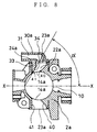
- Fig. 6 shows the configuration of the horizontal scavenging flow passage 22 of the first embodiment.
- a pair of the opening portions 23 and 23 are provided in both outer faces of the cylinder 2.
- the opening portion 23 and the scavenging port 14 are bored and connected by means of a drilling through-hole 27 which is a cutting through-hole 26 to form the horizontal scavenging flow passage 22.
- the drilling through-hole 27 inclines at a predetermined angle ⁇ to the X-X line connecting the central axis of the cylinder 2 and the center of the exhaust port 10 in plane view.
- the drilling through-hole 27 is directed to the inner face of the cylinder 2 opposite the exhaust port 10.
- a face 28 which is vertical to the axial direction of the drilling through-hole 27 is provided in the opening portion 23.
- the run off 25 is provided at the mounting seat 24 provided at the opening portion 23 so as to prevent interference with tools when the drilling through-hole 27 is wrought by a drill 29.
- the opening portion 23 is formed in the side wall of the cylinder 2 which is the extension of the horizontal scavenging flow passage 22 toward the outside of the cylinder 2, which enables the formation of the horizontal scavenging flow passage 22 and the scavenging port 14 by cutting work from the outside of the cylinder 2 with the use of the opening portion 23. Therefore, a projecting portion of a die casting die for forming a scavenging flow passage and a scavenging port which has been conventionally required becomes unnecessary, thus simplifying a die casting die for forming the scavenging flow passage and the vicinity of the scavenging port and reducing the number of die casting dies. Accordingly, the die-casting die can be structurally simplified, decreased in size compared with the conventional one, and easily manufactured, whereby the manufacturing processes of the cylinder 2 are decreased. As a result, the less expensive cylinder 2 can be manufactured.
- the positions, directions, diameter dimensions, and the like of the horizontal scavenging flow passage 22 and the scavenging port 14 can be precisely wrought by simple cutting work such as drilling work or the like, thereby forming the scavenging flow passage 20 with great precision and good scavenging performance. Accordingly, the high quality cylinder 2 can be manufactured at low cost.
- the horizontal scavenging flow passage 22 and the scavenging port 14 are formed in such a manner that the axis thereof is directed to the inner face of the cylinder 2 opposite the exhaust port 10.
- air at the time of scavenge is sent into the inner part on the opposite side of the exhaust port 10 of the cylinder 2 and exhaust gas at the inner part of the cylinder 2 is exhausted through the exhaust port 10, which enables efficient scavenge.
- the drill 29 never slides, whereby drilling work can be easily conducted with excellent positioning accuracy.
- the opening portion 23 never interferes with the drill 29 and thus the cylinder 2 of good quality can be manufactured.
- FIG. 7 is a front view of a cylinder 2a.
- the upper portion of Fig. 8 shows a state that an air supply flow passage member 30a is attached to the cylinder 2a.
- rectangular opening portions 23a and 23a in side view are provided on both side faces of the cylinder 2a.
- the opening portion 23a penetrates to a scavenging port 14a which is provided in the inner wall surface of the cylinder 2a.
- an inclined face 40 is provided on the exhaust port 10 side of the inner face of the opening portion 23a in such a manner to go away from the exhaust port 10 from the outside toward the inside of the cylinder 2a.
- a face 41 which is vertical to the line X-X connecting the central axis of the cylinder 2a and the center of the exhaust port 10 in plane view.
- an air supply flow passage member 30a having the air supply flow passage 31 is mounted to cover the opening portion 23a.
- a protruding portion 33 which protrudes on the face 41 side of the opening portion 23a and along the face 41 is provided.
- an inclined guide face 34 is provided on the inside of the protruding portion 33 of the air supply flow passage member 30a.
- the guide face 34 is at an angle ⁇ to the line X-X.
- Formed by the inclined face 40 and the guide face 34 is a horizontal scavenging flow passage 22a which is directed to the inner face of the cylinder 2a opposite the exhaust port 10.
- the functional operation of the second embodiment is the same as that of the first embodiment and the explanation thereof is omitted.
- the horizontal scavenging flow passage 22a with an inclination of a predetermined angle ⁇ to the central axis of the cylinder 2a is formed by cutting work, the light and small air supply flow passage member 30a is separately worked. Therefore, handling and working is easier compared with the configuration in which the heavy and large-sized cylinder 2a itself is directly wrought. Consequently, working man-hour can be decreased.
- the opening portion 23a is rectangular in side view and the air guide face 34 of the air supply flow passage member 30a has a flat surface in this embodiment, the opening portion 23a and the air guide face 34 may have other shapes, for example, the opening portion 23a may be rounded at both ends and the air guide face 34 may have an arc-shaped surface.
- the first and second embodiments are described on the assumption of die casting, but different casting such as gravity casting, high pressure casting, or the like is also possible.
Landscapes
- Engineering & Computer Science (AREA)
- Chemical & Material Sciences (AREA)
- Combustion & Propulsion (AREA)
- Mechanical Engineering (AREA)
- General Engineering & Computer Science (AREA)
- Cylinder Crankcases Of Internal Combustion Engines (AREA)
Abstract
Description
- The present invention relates to a cylinder for a stratified scavenging two-cycle engine, and more particularly to a scavenging flow passage of the cylinder.
- Conventionally, in a scavenging flow passage for a stratified scavenging two-cycle engine, a method is frequently adopted in order to certainly conduct stratified scavenge, in which a crank chamber and the inside of a cylinder are connected with a hooked scavenging flow passage composed of a vertical scavenging flow passage provided outside a cylinder wall and a horizontal scavenging flow passage for connection between the vertical scavenging flow passage and the cylinder. The scavenging flow passage is often manufactured by gravity casting. This method, however, has a disadvantage that the cost is high, and therefore manufacture by die-cast is desired. Examples of solutions to the above disadvantage are proposals made in Japanese Patent Publication No. 6-96185 and Japanese Utility Model Publication No. 1-18813.
- According to an art disclosed in Japanese Patent Publication No.6-96185, a cylinder liner is set within a cylinder portion forming space which is formed in the inside with a plurality of die casting dies. A scavenging passage horizontal portion penetrating to the outside of the cylinder and a scavenging passage vertical portion are formed with the die casting dies, and molten metal is poured into them. After the molten metal is solidified, the die casting dies are removed, and a blank cap is inserted into a portion of the scavenging passage horizontal portion penetrating in the outside to form a scavenging passage.
- According to the aforesaid configuration, the cylinder liner is used for the cylinder portion formed by the plurality of die casting dies. In addition, in order to form a scavenging passage into the cylinder, a die casting die protruding portion is formed in such a manner to form the scavenging passage horizontal portion penetrating to the outside of the cylinder with the die casting die. After casting, the die casting die protruding portion is pulled out, and the blank cap is inserted into the formed scavenging passage horizontal portion to form the scavenging passage. Thus, the number of used parts such as the cylinder liner, die casting die protruding portion, blank cap, and the like increases. Moreover, since the die casting die protruding portion is formed, the die becomes more complicate and large-sized and cylinder manufacturing processes and working hours are increased. As a result, there arises a disadvantage that the cost of manufacturing the cylinder is high.
- According to an art disclosed in Japanese Utility Model Publication No. 1-18813, an adapter including a scavenging passage forming wall surface and a suction passage is separately formed, and the adapter is attached to an adapter attaching face formed in the cylinder to form the scavenging passage.
- In the aforesaid configuration, however, the adapter which is separately formed is attached to the adapter attaching face formed on the outer peripheral face of the cylinder to form the scavenging passage, thereby increasing the number of the parts, complicating and increasing the manufacturing processes. Consequently, there arise disadvantages that it takes more time to manufacture the cylinder and the manufacturing cost becomes higher.
- In view of the aforesaid disadvantages, an object of the present invention is to provide a cylinder for a stratified scavenging two-cycle engine, which can be cast by die-cast, has excellent scavenging performance and a structurally simple scavenging flow passage, and is manufactured at low cost.
- A cylinder for a stratified scavenging two-cycle engine according to the present invention is characterized in that in a cylinder for a stratified scavenging two-cycle engine including a piston, a cylinder housing the piston to be vertically slidable, a crankcase connected to the cylinder, an exhaust port and a scavenging port each provided in a side wall of the cylinder, a vertical scavenging flow passage provided within the side wall of the cylinder, whose lower end portion is connected to a crank chamber provided within the crankcase wall, a horizontal scavenging flow passage for connection between the upper end portion of the vertical scavenging flow passage and the scavenging port, an air supply flow passage supplying air through a check valve to a scavenging flow passage having the vertical scavenging flow passage and the horizontal scavenging flow passage, and a mixture supply flow passage supplying mixture from a fuel supply means to the crank chamber, an opening portion is provided in the side wall of the cylinder which is the extension of the horizontal scavenging flow passage toward the outside of the cylinder.
- According to the aforesaid configuration, the opening portion is provided in the side wall of the cylinder which is the extension of the horizontal scavenging flow passage toward the outside of the cylinder, which enables the formation of the horizontal scavenging flow passage by cutting from the outside of the cylinder through the opening portion after manufacturing the cylinder without forming the horizontal scavenging flow passage by casting. Accordingly, in casting the cylinder, a die for forming the horizontal scavenging flow passage becomes unnecessary, thus making it possible to manufacture the cylinder with a small-sized and structurally simple die casting die. Consequently, the number of parts of the die and the manufacturing processes decrease, whereby the cylinder can be manufactured at low cost.
- Moreover, the scavenging port and the horizontal scavenging flow passage may be formed through a cutting through-hole which penetrates the opening portion and the inner face of the cylinder.
- According to the aforesaid configuration, since the scavenging port and the horizontal scavenging flow passage are formed by cutting work, the positions, directions, diameter dimensions, and the like of the scavenging port and the horizontal scavenging flow passage can be precisely wrought. In addition, the aforesaid configuration can easily cope with the design change of the horizontal scavenging flow passage without changing the design of the casting die by setting the position, direction, diameter dimension, and the like in cutting work at predetermined values, whereby the cylinder with good scavenging performance can be manufactured at low cost.
- Further, it is possible that the cutting through-hole is bored with an inclination of a predetermined angle to a line passing the central axis of the cylinder in plane view, and the opening portion is provided with a face which is vertical to the axis of the cutting through-hole and provided with a run off for preventing interference with tools in cutting work at a mounting seat for an air supply flow passage member disposed at the outer rim thereof.
- According to the aforesaid configuration, it is possible to form the scavenging port and the horizontal scavenging flow passage toward the inner face of the cylinder opposite the exhaust port by boring the cutting through-hole in such a manner that the axial direction of the cutting through-hole inclines at a predetermined angle to a line passing the central axis of the cylinder in plane view. Accordingly, the directions of the scavenging port and the horizontal scavenging flow passage can be properly set so as to improve scavenging performance. Thus, air is sent into the inner part of the cylinder opposite the exhaust port at the time of scavenge to thereby push out exhaust gas into the exhaust port, which leads to the improvement of scavenging performance. Besides, since the opening portion is provided with the face which is vertical to the axis of the cutting through-hole, tools such as a drill, an end mill, and the like never slide in working, whereby cutting work can be surely and easily conducted. Incidentally, the face vertical to the axis of the cutting through-hole may be a face which remains cast or a wrought face. In addition, since the run off for preventing interference with tools in cutting work is provided at the mounting seat for the air supply flow passage member, the cutting work is easily conducted without interference, thus improving product quality, decreasing working man-hour, and enabling the manufacture of low-cost cylinders.
- Furthermore, it is possible that an air supply flow passage member having a protruding portion is attached to cover the opening portion, the protruding portion protrudes into the opening portion, and a guide face with an inclination of a predetermined angle is provided at the front end portion of the protruding portion, and
the horizontal scavenging flow passage is formed with an inclination of a predetermined angle to a line passing the central axis of the cylinder in plane view. - According to the aforesaid configuration, the protruding portion having the guide face with an inclination of a predetermined angle at the front end portion thereof is provided at the air supply flow passage member, the air supply flow passage member being attached to the opening portion, which makes it possible that the horizontal scavenging flow passage is formed to slant toward the inner face of the cylinder opposite the exhaust port. Therefore, air is sent into the inner part of the cylinder along the guide face, thus improving scavenging performance. The light and small air supply flow passage member is wrought without directly working a heavy cylinder, thereby facilitating handling in working and reducing the working cost.
-
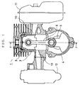
- Fig. 1 is a front sectional view of a stratified scavenging two-cycle engine including a cylinder of the present invention;
- Fig. 2 is a sectional view taken along the 2-2 line in Fig. 1;
- Fig. 3 is a front sectional view of a cylinder of a first embodiment of the present invention;
- Fig. 4 is a sectional view taken along the 4-4 line in Fig. 3;
- Fig. 5 is a front view of the cylinder seen from the
arrow 5 in Fig. 4; - Fig. 6 is a sectional view taken along the 6-6 line in Fig. 3;
- Fig. 7 is a front view of a cylinder of a second embodiment of the present invention;
- Fig. 8 is a sectional view taken along the 8-8 line in Fig. 7; and
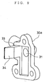
- Fig. 9 is a perspective view of an air supply flow passage member of the second embodiment of the present invention.
-
- Preferable embodiments of the present invention will be described in detail below with reference to the attached drawings.
- In Fig. 1, a piston 3 is housed vertically and slidably in a
cylinder 2 for a stratified scavenging two-cycle engine 1, and acrankcase 4 is attached to the lower end face of thecylinder 2. Acrankshaft 5 is rotatably attached in thecrankcase 4, and the piston 3 and thecrankshaft 5 are connected with aconnecting rod 6. Anexhaust port 10 is formed on one side of the wall surface of thecylinder 2 and connected to amuffler 11. Formed on the other side of the wall surface of thecylinder 2 is a mixturesupply flow passage 13 connected to a carburetor (a fuel supply means) 12. - In Fig. 2, a pair of
scavenging ports cylinder 2, and eachscavenging port 14 communicates with acrank chamber 7 through ascavenging flow passage 20 formed within the wall of thecylinder 2. The upper portion of thescavenging flow passage 20 leads to the outside through anopening portion 23. An airsupply flow passage 31 is provided in an air supplyflow passage member 30 attached to theopening portion 23, the airsupply flow passage 31 being connected to thescavenging flow passage 20 through acheck valve 32 which is disposed between the airsupply flow passage 31 and theopening portion 23. Eachcheck valve 32 includes a check valve stopper 32a as a stopper plate. - In a scavenging stroke, when the piston 3 descends, first the
exhaust port 10 opens, subsequently thescavenging port 14 opens, and air which flows in from the airsupply flow passage 31 is compressed to thereby flow into thecylinder 2 so that exhaust gas is exhausted through theexhaust port 10. Next, mixture flows into thecylinder 2 from thescavenging flow passage 20 to thereby conduct stratified scavenge. - The configuration of the
cylinder 2 will be described in detail below. Fig. 3 shows thecylinder 2 of a first embodiment. Theexhaust port 10, a mixturesupply flow passage 13, and thescavenging port 14 are formed in the wall surface of thecylinder 2. - In Fig. 4, a pair of the scavenging
flow passages cylinder 2. The scavengingflow passage 20 is composed of a verticalscavenging flow passage 21 which penetrates the lower end portion of thecylinder 2 and a horizontalscavenging flow passage 22 for connection between the upper end portion of the verticalscavenging flow passage 21 and the scavengingport 14. In thescavenging flow passage 20, the openingportion 23 is formed in the side wall of thecylinder 2 which is the extension of the horizontalscavenging flow passage 22 toward the outside of thecylinder 2. - In Fig. 5, a mounting
seat 24 for mounting the air supply flow passage member 30 (See Fig. 2) is formed at the outer rim of the openingportion 23, and a run off 25 is provided on one side of a portion surrounding the openingportion 23 of the mountingseat 24. - Fig. 6 shows the configuration of the horizontal
scavenging flow passage 22 of the first embodiment. A pair of the openingportions cylinder 2. The openingportion 23 and the scavengingport 14 are bored and connected by means of a drilling through-hole 27 which is a cutting through-hole 26 to form the horizontalscavenging flow passage 22. The drilling through-hole 27 inclines at a predetermined angle α to the X-X line connecting the central axis of thecylinder 2 and the center of theexhaust port 10 in plane view. The drilling through-hole 27 is directed to the inner face of thecylinder 2 opposite theexhaust port 10. Aface 28 which is vertical to the axial direction of the drilling through-hole 27 is provided in the openingportion 23. In addition, the run off 25 is provided at the mountingseat 24 provided at the openingportion 23 so as to prevent interference with tools when the drilling through-hole 27 is wrought by adrill 29. - As described above, in the
cylinder 2 according to the present invention, the openingportion 23 is formed in the side wall of thecylinder 2 which is the extension of the horizontalscavenging flow passage 22 toward the outside of thecylinder 2, which enables the formation of the horizontalscavenging flow passage 22 and the scavengingport 14 by cutting work from the outside of thecylinder 2 with the use of the openingportion 23. Therefore, a projecting portion of a die casting die for forming a scavenging flow passage and a scavenging port which has been conventionally required becomes unnecessary, thus simplifying a die casting die for forming the scavenging flow passage and the vicinity of the scavenging port and reducing the number of die casting dies. Accordingly, the die-casting die can be structurally simplified, decreased in size compared with the conventional one, and easily manufactured, whereby the manufacturing processes of thecylinder 2 are decreased. As a result, the lessexpensive cylinder 2 can be manufactured. - Moreover, the positions, directions, diameter dimensions, and the like of the horizontal
scavenging flow passage 22 and the scavengingport 14 can be precisely wrought by simple cutting work such as drilling work or the like, thereby forming the scavengingflow passage 20 with great precision and good scavenging performance. Accordingly, thehigh quality cylinder 2 can be manufactured at low cost. - The horizontal
scavenging flow passage 22 and the scavengingport 14 are formed in such a manner that the axis thereof is directed to the inner face of thecylinder 2 opposite theexhaust port 10. Thus, air at the time of scavenge is sent into the inner part on the opposite side of theexhaust port 10 of thecylinder 2 and exhaust gas at the inner part of thecylinder 2 is exhausted through theexhaust port 10, which enables efficient scavenge. In addition, when the horizontalscavenging flow passage 22 and the scavengingport 14 are drilled, thedrill 29 never slides, whereby drilling work can be easily conducted with excellent positioning accuracy. Moreover, when working is conducted with thedrill 29 being tilted, the openingportion 23 never interferes with thedrill 29 and thus thecylinder 2 of good quality can be manufactured. - Next, a cylinder of a second embodiment of the present invention will be described. Fig. 7 is a front view of a
cylinder 2a. The upper portion of Fig. 8 shows a state that an air supplyflow passage member 30a is attached to thecylinder 2a. In Figs. 7 and 8,rectangular opening portions cylinder 2a. Theopening portion 23a penetrates to a scavengingport 14a which is provided in the inner wall surface of thecylinder 2a. As shown in the lower portion of Fig. 8, aninclined face 40 is provided on theexhaust port 10 side of the inner face of theopening portion 23a in such a manner to go away from theexhaust port 10 from the outside toward the inside of thecylinder 2a. Provided on the opposite side of theexhaust port 10 of the inner face of theopening portion 23a is aface 41 which is vertical to the line X-X connecting the central axis of thecylinder 2a and the center of theexhaust port 10 in plane view. - As shown in the upper portion of Fig. 8, on a mounting
seat 24a provided at the outer rim of theopening portion 23a, an air supplyflow passage member 30a having the airsupply flow passage 31 is mounted to cover theopening portion 23a. At the front end portion of the air supplyflow passage member 30a, a protrudingportion 33 which protrudes on theface 41 side of theopening portion 23a and along theface 41 is provided. As shown in Figs. 8 and 9, an inclined guide face 34 is provided on the inside of the protrudingportion 33 of the air supplyflow passage member 30a. As shown in Fig. 8, theguide face 34 is at an angle α to the line X-X. Formed by theinclined face 40 and theguide face 34 is a horizontalscavenging flow passage 22a which is directed to the inner face of thecylinder 2a opposite theexhaust port 10. - The functional operation of the second embodiment is the same as that of the first embodiment and the explanation thereof is omitted. According to the present configuration, when the horizontal
scavenging flow passage 22a with an inclination of a predetermined angle α to the central axis of thecylinder 2a is formed by cutting work, the light and small air supplyflow passage member 30a is separately worked. Therefore, handling and working is easier compared with the configuration in which the heavy and large-sized cylinder 2a itself is directly wrought. Consequently, working man-hour can be decreased. Although theopening portion 23a is rectangular in side view and the air guide face 34 of the air supplyflow passage member 30a has a flat surface in this embodiment, theopening portion 23a and theair guide face 34 may have other shapes, for example, theopening portion 23a may be rounded at both ends and theair guide face 34 may have an arc-shaped surface. - The first and second embodiments are described on the assumption of die casting, but different casting such as gravity casting, high pressure casting, or the like is also possible.
Claims (4)
- A cylinder for a stratified scavenging two-cycle engine including a piston (3), a cylinder (2, 2a) housing said piston (3) to be vertically slidable, a crankcase (4) connected to said cylinder (2, 2a), an exhaust port (10) and a scavenging port (14) each provided in a side wall of said cylinder (2, 2a), a vertical scavenging flow passage (21) provided within the side wall of said cylinder (2, 2a), whose lower end portion is connected to a crank chamber (7) provided within said crankcase (4) wall, a horizontal scavenging flow passage (22, 22a) for connection between the upper end portion of said vertical scavenging flow passage (21) and said scavenging port (14), an air supply flow passage (31) supplying air through a check valve (32) to a scavenging flow passage (20) having said vertical scavenging flow passage (21) and said horizontal scavenging flow passage (22, 22a), and a mixture supply flow passage (13) supplying mixture from a fuel supply means (12) to said crank chamber (7),
wherein an opening portion (23, 23a) is provided in the side wall of said cylinder (2, 2a) which is the extension of said horizontal scavenging flow passage (22, 22a) toward the outside of said cylinder (2, 2a). - The cylinder for the stratified scavenging two-cycle engine in accordance with Claim 1,
wherein said scavenging port (14) and said horizontal scavenging flow passage (22) are formed through a cutting through-hole (26) which penetrates said opening portion (23) and the inner face of said cylinder (2). - The cylinder for the stratified scavenging two-cycle engine in accordance with Claim 2,
wherein said cutting through-hole (26) is bored with an inclination of a predetermined angle ( α ) to a line passing the central axis of said cylinder (2) in plane view, and
wherein said opening portion (23) is provided with a face (28) which is vertical to the axis of said cutting through-hole (26) and provided with a run off (25) for preventing interference with tools in cutting work at a mounting seat (24) for an air supply flow passage member (30) disposed at the outer rim thereof. - The cylinder for the stratified scavenging two-cycle engine in accordance with Claim 1,
wherein an air supply flow passage member (30a) having a protruding portion (33) is attached to cover said opening portion (23a), said protruding portion (33) protrudes into said opening portion (23a), and a guide face (34) with an inclination of a predetermined angle is provided at the front end portion of the protruding portion, and
wherein said horizontal scavenging flow passage (22a) is formed with an inclination of a predetermined angle ( α ) to a line passing the central axis of said cylinder (2a) in plane view.
Applications Claiming Priority (2)
| Application Number | Priority Date | Filing Date | Title |
|---|---|---|---|
| JP32446798 | 1998-10-30 | ||
| JP10324467A JP3040758B1 (en) | 1998-10-30 | 1998-10-30 | Cylinder of stratified scavenging two-cycle engine |
Publications (4)
| Publication Number | Publication Date |
|---|---|
| EP0997620A2 true EP0997620A2 (en) | 2000-05-03 |
| EP0997620A3 EP0997620A3 (en) | 2000-12-13 |
| EP0997620B1 EP0997620B1 (en) | 2002-09-18 |
| EP0997620B2 EP0997620B2 (en) | 2005-12-07 |
Family
ID=18166146
Family Applications (1)
| Application Number | Title | Priority Date | Filing Date |
|---|---|---|---|
| EP99100729A Expired - Lifetime EP0997620B2 (en) | 1998-10-30 | 1999-01-15 | Cylinder for stratified scavenging two-cycle engine |
Country Status (4)
| Country | Link |
|---|---|
| US (1) | US6152093A (en) |
| EP (1) | EP0997620B2 (en) |
| JP (1) | JP3040758B1 (en) |
| DE (1) | DE69902981T3 (en) |
Cited By (8)
| Publication number | Priority date | Publication date | Assignee | Title |
|---|---|---|---|---|
| US6668771B2 (en) | 2000-01-14 | 2003-12-30 | Aktiebolaget Electrolux | Two-stroke internal combustion engine |
| US6668770B2 (en) | 2000-01-14 | 2003-12-30 | Aktiebolaget Electrolux | Two-stroke interal combustion engine |
| US6712029B1 (en) | 1999-01-19 | 2004-03-30 | Lars Andersson | Cylinder for an internal combustion engine |
| US6718917B2 (en) | 2000-04-27 | 2004-04-13 | Aktiebolaget Electrolux | Two-stroke internal combustion engine |
| US6877723B2 (en) | 2000-01-14 | 2005-04-12 | Aktiebolaget Electrolux | Valve for control of additional air for a two-stroke engine |
| US7082910B2 (en) | 1999-01-19 | 2006-08-01 | Aktiebolaget Electrolux | Two-stroke internal combustion engine |
| EP1288462A3 (en) * | 2001-08-28 | 2007-06-06 | Techtronic Industries Co., Ltd. | Injection port for internal combustion engine |
| DE102004029379B4 (en) * | 2003-06-25 | 2008-08-21 | Kioritz Corp., Ohme | Method for producing a cylinder for an internal combustion engine |
Families Citing this family (17)
| Publication number | Priority date | Publication date | Assignee | Title |
|---|---|---|---|---|
| DE10009793A1 (en) * | 2000-03-01 | 2001-09-06 | Stihl Maschf Andreas | 2-stroke engine with adjustable charge for chain saws etc. has overflow channels connected to air feed channels with adjustable throttles for different air flow volume in individual channels |
| US6397795B2 (en) | 2000-06-23 | 2002-06-04 | Nicholas S. Hare | Engine with dry sump lubrication, separated scavenging and charging air flows and variable exhaust port timing |
| JP2002054443A (en) | 2000-08-14 | 2002-02-20 | Kioritz Corp | Two-cycle internal combustion engine |
| DE10044023A1 (en) * | 2000-09-06 | 2002-03-14 | Stihl Maschf Andreas | Two-stroke engine with air purge |
| US6460493B2 (en) | 2000-12-28 | 2002-10-08 | The United States Of America As Represented By The Secretary Of The Air Force | Uniflow scavenging microengine |
| US6564760B2 (en) | 2001-09-20 | 2003-05-20 | Imack Laydera-Collins | Stratified scavenging two-cycle internal combustion engine |
| DE10158397B4 (en) * | 2001-11-28 | 2014-11-06 | Andreas Stihl Ag & Co. | Method for producing a cylinder in a two-stroke engine |
| US6644263B2 (en) | 2001-12-04 | 2003-11-11 | Nicholas S. Hare | Engine with dry sump lubrication |
| DE10160539B4 (en) | 2001-12-10 | 2017-06-08 | Andreas Stihl Ag & Co. | Two-stroke engine with flushing template and single-inlet carburetor |
| US6708958B1 (en) | 2002-10-04 | 2004-03-23 | Electrolux Home Products, Inc. | Air valve mechanism for two-cycle engine |
| US6848399B2 (en) * | 2003-05-30 | 2005-02-01 | Electrolux Home Products, Inc. | Scavenging insert for an engine |
| JP4061252B2 (en) * | 2003-08-11 | 2008-03-12 | ザマ・ジャパン株式会社 | Two-cycle engine carburetor |
| US6973899B2 (en) * | 2004-02-23 | 2005-12-13 | Electrolux Home Products, Inc. | Stratified air scavenged two-cycle engine with air flow |
| US8534268B2 (en) * | 2009-09-14 | 2013-09-17 | Nagesh Mavinahally | Two-stroke engine |
| CN103032151A (en) * | 2011-09-29 | 2013-04-10 | 浙江派尼尔机电有限公司 | Air-replenishing scavenging engine |
| CN103061861B (en) * | 2012-11-25 | 2015-04-22 | 宁波大叶园林设备有限公司 | Emission-reduction two-stroke gasoline engine with scavenging passage wedge turbulent flow return sheets |
| CN115263528B (en) * | 2022-07-01 | 2024-05-10 | 长沙光华航空科技有限公司 | Engine air-dispelling structure and engine |
Citations (2)
| Publication number | Priority date | Publication date | Assignee | Title |
|---|---|---|---|---|
| JPS6418813A (en) | 1987-07-14 | 1989-01-23 | Fujitsu Ltd | Automatic power supply control system |
| JPH0696185A (en) | 1992-09-17 | 1994-04-08 | Nippon Telegr & Teleph Corp <Ntt> | Browsing display processing method for image |
Family Cites Families (10)
| Publication number | Priority date | Publication date | Assignee | Title |
|---|---|---|---|---|
| DE653500C (en) * | 1936-05-21 | 1937-11-25 | Auto Union A G | Multi-cylinder, slot-controlled two-stroke internal combustion engine |
| GB1285471A (en) * | 1969-02-04 | 1972-08-16 | Frank Davison | Improvements in two-stroke internal combustion engines for chainsaws |
| US3881454A (en) * | 1972-10-16 | 1975-05-06 | Motobecane Ateliers | Two stroke engine construction |
| US4026254A (en) * | 1975-05-22 | 1977-05-31 | Outboard Marine Corporation | Two stroke internal combustion engine and method of operation thereof |
| US4294202A (en) * | 1978-09-12 | 1981-10-13 | Performance Industries, Inc. | Fuel porting for two cycle internal combustion engine |
| US4306522A (en) * | 1980-06-19 | 1981-12-22 | Briggs & Stratton Corporation | Transfer port duct for two-stroke engines |
| JPS59153950A (en) * | 1983-02-18 | 1984-09-01 | Nippon Clean Engine Res | Scavenging hole forming method of two-cycle engine |
| JPH06193451A (en) * | 1992-12-22 | 1994-07-12 | Yamaha Motor Co Ltd | Two-cycle engine |
| JPH09217628A (en) * | 1996-02-13 | 1997-08-19 | Yamaha Motor Co Ltd | Two cycle engine |
| JPH10121975A (en) * | 1996-10-17 | 1998-05-12 | Sekiyu Sangyo Kasseika Center | Stratiformly scavenging two-cycle engine |
-
1998
- 1998-10-30 JP JP10324467A patent/JP3040758B1/en not_active Expired - Lifetime
-
1999
- 1999-01-15 DE DE69902981T patent/DE69902981T3/en not_active Expired - Lifetime
- 1999-01-15 EP EP99100729A patent/EP0997620B2/en not_active Expired - Lifetime
- 1999-02-16 US US09/250,764 patent/US6152093A/en not_active Expired - Lifetime
Patent Citations (2)
| Publication number | Priority date | Publication date | Assignee | Title |
|---|---|---|---|---|
| JPS6418813A (en) | 1987-07-14 | 1989-01-23 | Fujitsu Ltd | Automatic power supply control system |
| JPH0696185A (en) | 1992-09-17 | 1994-04-08 | Nippon Telegr & Teleph Corp <Ntt> | Browsing display processing method for image |
Cited By (10)
| Publication number | Priority date | Publication date | Assignee | Title |
|---|---|---|---|---|
| US6712029B1 (en) | 1999-01-19 | 2004-03-30 | Lars Andersson | Cylinder for an internal combustion engine |
| US7025021B1 (en) | 1999-01-19 | 2006-04-11 | Aktiebolaget Electrolux | Two-stroke internal combustion engine |
| US7082910B2 (en) | 1999-01-19 | 2006-08-01 | Aktiebolaget Electrolux | Two-stroke internal combustion engine |
| US7574984B2 (en) | 1999-01-19 | 2009-08-18 | Husqvarna Ab | Two-stroke internal combustion engine |
| US6668771B2 (en) | 2000-01-14 | 2003-12-30 | Aktiebolaget Electrolux | Two-stroke internal combustion engine |
| US6668770B2 (en) | 2000-01-14 | 2003-12-30 | Aktiebolaget Electrolux | Two-stroke interal combustion engine |
| US6877723B2 (en) | 2000-01-14 | 2005-04-12 | Aktiebolaget Electrolux | Valve for control of additional air for a two-stroke engine |
| US6718917B2 (en) | 2000-04-27 | 2004-04-13 | Aktiebolaget Electrolux | Two-stroke internal combustion engine |
| EP1288462A3 (en) * | 2001-08-28 | 2007-06-06 | Techtronic Industries Co., Ltd. | Injection port for internal combustion engine |
| DE102004029379B4 (en) * | 2003-06-25 | 2008-08-21 | Kioritz Corp., Ohme | Method for producing a cylinder for an internal combustion engine |
Also Published As
| Publication number | Publication date |
|---|---|
| JP3040758B1 (en) | 2000-05-15 |
| JP2000136725A (en) | 2000-05-16 |
| EP0997620A3 (en) | 2000-12-13 |
| DE69902981T2 (en) | 2003-01-23 |
| US6152093A (en) | 2000-11-28 |
| EP0997620B1 (en) | 2002-09-18 |
| DE69902981T3 (en) | 2006-08-24 |
| DE69902981D1 (en) | 2002-10-24 |
| EP0997620B2 (en) | 2005-12-07 |
Similar Documents
| Publication | Publication Date | Title |
|---|---|---|
| EP0997620B1 (en) | Cylinder for stratified scavenging two-cycle engine | |
| AU2007201958B2 (en) | Monolithic cylinder-crankcase | |
| US6279456B1 (en) | Piston | |
| EP0933514A1 (en) | Stratified scavenging two-cycle engine | |
| EP1774150B1 (en) | A crankcase scavenged two-stroke internal combustion engine having an additional air supply. | |
| US6691650B2 (en) | Piston valve type layered scavenging 2-cycle engine | |
| US4261305A (en) | Two cycle internal combustion engine | |
| US6431159B2 (en) | Oil separator structure of internal combustion engine | |
| US7096843B2 (en) | Multicylinder four-cycle combustion engine | |
| US7331276B2 (en) | Piston for a two-cycle engine | |
| EP1284355B1 (en) | Cylinder head and crankcase manufacturing and assembly techniques | |
| CN211202137U (en) | Cylinder block oil return ventilation structure and engine | |
| US6324961B1 (en) | Oil passage arrangement in a piston | |
| US4637110A (en) | Method for making a composite cylinder block | |
| JPH0118813Y2 (en) | ||
| US4922863A (en) | Cast engine cylinder having an internal passageway and method of making same | |
| US6848398B2 (en) | Two-cycle engine | |
| US4970769A (en) | Method for producing cylinder having scavenging passages for two-cycle internal combustion engine | |
| US5190004A (en) | Internal combustion engine | |
| JP4586035B2 (en) | Cylinder block of internal combustion engine and manufacturing method thereof | |
| US4210108A (en) | Stepped piston two-stroke engines | |
| JPH0138279Y2 (en) | ||
| CN216045393U (en) | Back vice cylinder head assembly | |
| JPH0826791B2 (en) | Variable compression ratio device for internal combustion engine | |
| JPH10159531A (en) | Oil level gage installing structure for engine |
Legal Events
| Date | Code | Title | Description |
|---|---|---|---|
| PUAI | Public reference made under article 153(3) epc to a published international application that has entered the european phase |
Free format text: ORIGINAL CODE: 0009012 |
|
| 17P | Request for examination filed |
Effective date: 19990126 |
|
| AK | Designated contracting states |
Kind code of ref document: A2 Designated state(s): DE FR GB IT SE |
|
| AX | Request for extension of the european patent |
Free format text: AL;LT;LV;MK;RO;SI |
|
| PUAL | Search report despatched |
Free format text: ORIGINAL CODE: 0009013 |
|
| AK | Designated contracting states |
Kind code of ref document: A3 Designated state(s): AT BE CH CY DE DK ES FI FR GB GR IE IT LI LU MC NL PT SE |
|
| AX | Request for extension of the european patent |
Free format text: AL;LT;LV;MK;RO;SI |
|
| RAP1 | Party data changed (applicant data changed or rights of an application transferred) |
Owner name: KOMATSU ZENOAH CO. |
|
| 17Q | First examination report despatched |
Effective date: 20010717 |
|
| AKX | Designation fees paid |
Free format text: DE FR GB IT SE |
|
| GRAG | Despatch of communication of intention to grant |
Free format text: ORIGINAL CODE: EPIDOS AGRA |
|
| GRAG | Despatch of communication of intention to grant |
Free format text: ORIGINAL CODE: EPIDOS AGRA |
|
| GRAH | Despatch of communication of intention to grant a patent |
Free format text: ORIGINAL CODE: EPIDOS IGRA |
|
| GRAH | Despatch of communication of intention to grant a patent |
Free format text: ORIGINAL CODE: EPIDOS IGRA |
|
| GRAA | (expected) grant |
Free format text: ORIGINAL CODE: 0009210 |
|
| AK | Designated contracting states |
Kind code of ref document: B1 Designated state(s): DE FR GB IT SE |
|
| REG | Reference to a national code |
Ref country code: GB Ref legal event code: FG4D |
|
| REF | Corresponds to: |
Ref document number: 69902981 Country of ref document: DE Date of ref document: 20021024 |
|
| ET | Fr: translation filed | ||
| PLBQ | Unpublished change to opponent data |
Free format text: ORIGINAL CODE: EPIDOS OPPO |
|
| PLBI | Opposition filed |
Free format text: ORIGINAL CODE: 0009260 |
|
| PLAX | Notice of opposition and request to file observation + time limit sent |
Free format text: ORIGINAL CODE: EPIDOSNOBS2 |
|
| 26 | Opposition filed |
Opponent name: FIRMA ANDREAS STIHL Effective date: 20030526 |
|
| PLAX | Notice of opposition and request to file observation + time limit sent |
Free format text: ORIGINAL CODE: EPIDOSNOBS2 |
|
| PLBB | Reply of patent proprietor to notice(s) of opposition received |
Free format text: ORIGINAL CODE: EPIDOSNOBS3 |
|
| PLAQ | Examination of admissibility of opposition: information related to despatch of communication + time limit deleted |
Free format text: ORIGINAL CODE: EPIDOSDOPE2 |
|
| PLAR | Examination of admissibility of opposition: information related to receipt of reply deleted |
Free format text: ORIGINAL CODE: EPIDOSDOPE4 |
|
| PLBQ | Unpublished change to opponent data |
Free format text: ORIGINAL CODE: EPIDOS OPPO |
|
| PLAB | Opposition data, opponent's data or that of the opponent's representative modified |
Free format text: ORIGINAL CODE: 0009299OPPO |
|
| PLBP | Opposition withdrawn |
Free format text: ORIGINAL CODE: 0009264 |
|
| PUAH | Patent maintained in amended form |
Free format text: ORIGINAL CODE: 0009272 |
|
| STAA | Information on the status of an ep patent application or granted ep patent |
Free format text: STATUS: PATENT MAINTAINED AS AMENDED |
|
| 27A | Patent maintained in amended form |
Effective date: 20051207 |
|
| AK | Designated contracting states |
Kind code of ref document: B2 Designated state(s): DE FR GB IT SE |
|
| REG | Reference to a national code |
Ref country code: SE Ref legal event code: RPEO |
|
| REG | Reference to a national code |
Ref country code: FR Ref legal event code: RN |
|
| REG | Reference to a national code |
Ref country code: FR Ref legal event code: FC |
|
| EN | Fr: translation not filed | ||
| ET3 | Fr: translation filed ** decision concerning opposition | ||
| EN | Fr: translation not filed | ||
| PG25 | Lapsed in a contracting state [announced via postgrant information from national office to epo] |
Ref country code: FR Free format text: LAPSE BECAUSE OF FAILURE TO SUBMIT A TRANSLATION OF THE DESCRIPTION OR TO PAY THE FEE WITHIN THE PRESCRIBED TIME-LIMIT Effective date: 20070126 |
|
| REG | Reference to a national code |
Ref country code: FR Ref legal event code: TP |
|
| REG | Reference to a national code |
Ref country code: FR Ref legal event code: CD |
|
| PGFP | Annual fee paid to national office [announced via postgrant information from national office to epo] |
Ref country code: SE Payment date: 20090108 Year of fee payment: 11 |
|
| PGFP | Annual fee paid to national office [announced via postgrant information from national office to epo] |
Ref country code: IT Payment date: 20100119 Year of fee payment: 12 |
|
| EUG | Se: european patent has lapsed | ||
| REG | Reference to a national code |
Ref country code: FR Ref legal event code: EERR Free format text: CORRECTION DE BOPI 07/04 - 3.2. Ref country code: FR Ref legal event code: EERR Free format text: CORRECTION DE BOPI 06/32 - 3.2. |
|
| PG25 | Lapsed in a contracting state [announced via postgrant information from national office to epo] |
Ref country code: IT Free format text: LAPSE BECAUSE OF NON-PAYMENT OF DUE FEES Effective date: 20110115 |
|
| PG25 | Lapsed in a contracting state [announced via postgrant information from national office to epo] |
Ref country code: SE Free format text: LAPSE BECAUSE OF NON-PAYMENT OF DUE FEES Effective date: 20100116 |
|
| REG | Reference to a national code |
Ref country code: FR Ref legal event code: PLFP Year of fee payment: 17 |
|
| PGFP | Annual fee paid to national office [announced via postgrant information from national office to epo] |
Ref country code: FR Payment date: 20150111 Year of fee payment: 17 Ref country code: GB Payment date: 20150105 Year of fee payment: 17 |
|
| PGFP | Annual fee paid to national office [announced via postgrant information from national office to epo] |
Ref country code: DE Payment date: 20151104 Year of fee payment: 18 |
|
| GBPC | Gb: european patent ceased through non-payment of renewal fee |
Effective date: 20160115 |
|
| REG | Reference to a national code |
Ref country code: FR Ref legal event code: ST Effective date: 20160930 |
|
| PG25 | Lapsed in a contracting state [announced via postgrant information from national office to epo] |
Ref country code: GB Free format text: LAPSE BECAUSE OF NON-PAYMENT OF DUE FEES Effective date: 20160115 |
|
| PG25 | Lapsed in a contracting state [announced via postgrant information from national office to epo] |
Ref country code: FR Free format text: LAPSE BECAUSE OF FAILURE TO SUBMIT A TRANSLATION OF THE DESCRIPTION OR TO PAY THE FEE WITHIN THE PRESCRIBED TIME-LIMIT Effective date: 20160201 |
|
| REG | Reference to a national code |
Ref country code: DE Ref legal event code: R119 Ref document number: 69902981 Country of ref document: DE |
|
| PG25 | Lapsed in a contracting state [announced via postgrant information from national office to epo] |
Ref country code: DE Free format text: LAPSE BECAUSE OF NON-PAYMENT OF DUE FEES Effective date: 20170801 |