EP0997091A1 - Retail product display system - Google Patents
Retail product display system Download PDFInfo
- Publication number
- EP0997091A1 EP0997091A1 EP98402674A EP98402674A EP0997091A1 EP 0997091 A1 EP0997091 A1 EP 0997091A1 EP 98402674 A EP98402674 A EP 98402674A EP 98402674 A EP98402674 A EP 98402674A EP 0997091 A1 EP0997091 A1 EP 0997091A1
- Authority
- EP
- European Patent Office
- Prior art keywords
- track
- demonstration
- demonstration product
- display system
- locator
- Prior art date
- Legal status (The legal status is an assumption and is not a legal conclusion. Google has not performed a legal analysis and makes no representation as to the accuracy of the status listed.)
- Withdrawn
Links
- 238000004891 communication Methods 0.000 claims abstract description 79
- 239000011324 bead Substances 0.000 claims abstract description 41
- 239000011521 glass Substances 0.000 claims description 4
- 238000003825 pressing Methods 0.000 claims description 3
- 239000005338 frosted glass Substances 0.000 description 11
- 238000005286 illumination Methods 0.000 description 8
- 238000005520 cutting process Methods 0.000 description 6
- 230000001815 facial effect Effects 0.000 description 6
- 230000004048 modification Effects 0.000 description 4
- 238000012986 modification Methods 0.000 description 4
- XAGFODPZIPBFFR-UHFFFAOYSA-N aluminium Chemical compound [Al] XAGFODPZIPBFFR-UHFFFAOYSA-N 0.000 description 3
- 229910052782 aluminium Inorganic materials 0.000 description 3
- 239000004411 aluminium Substances 0.000 description 3
- 230000001747 exhibiting effect Effects 0.000 description 3
- 239000003292 glue Substances 0.000 description 3
- 239000000463 material Substances 0.000 description 3
- 230000000284 resting effect Effects 0.000 description 3
- 230000000694 effects Effects 0.000 description 2
- 238000003780 insertion Methods 0.000 description 2
- 230000037431 insertion Effects 0.000 description 2
- 239000000843 powder Substances 0.000 description 2
- 230000006978 adaptation Effects 0.000 description 1
- 239000003086 colorant Substances 0.000 description 1
- 239000002537 cosmetic Substances 0.000 description 1
- 230000000593 degrading effect Effects 0.000 description 1
- 230000003467 diminishing effect Effects 0.000 description 1
- 238000001125 extrusion Methods 0.000 description 1
- 238000001746 injection moulding Methods 0.000 description 1
- 239000004922 lacquer Substances 0.000 description 1
- 238000003698 laser cutting Methods 0.000 description 1
- 238000000034 method Methods 0.000 description 1
- 238000000465 moulding Methods 0.000 description 1
- 229910052754 neon Inorganic materials 0.000 description 1
- GKAOGPIIYCISHV-UHFFFAOYSA-N neon atom Chemical compound [Ne] GKAOGPIIYCISHV-UHFFFAOYSA-N 0.000 description 1
- 210000000056 organ Anatomy 0.000 description 1
- 238000005728 strengthening Methods 0.000 description 1
- 230000000007 visual effect Effects 0.000 description 1
Images


Classifications
-
- A—HUMAN NECESSITIES
- A47—FURNITURE; DOMESTIC ARTICLES OR APPLIANCES; COFFEE MILLS; SPICE MILLS; SUCTION CLEANERS IN GENERAL
- A47F—SPECIAL FURNITURE, FITTINGS, OR ACCESSORIES FOR SHOPS, STOREHOUSES, BARS, RESTAURANTS OR THE LIKE; PAYING COUNTERS
- A47F11/00—Arrangements in shop windows, shop floors or show cases
- A47F11/06—Means for bringing about special optical effects
- A47F11/10—Arrangements of light sources
-
- A—HUMAN NECESSITIES
- A47—FURNITURE; DOMESTIC ARTICLES OR APPLIANCES; COFFEE MILLS; SPICE MILLS; SUCTION CLEANERS IN GENERAL
- A47F—SPECIAL FURNITURE, FITTINGS, OR ACCESSORIES FOR SHOPS, STOREHOUSES, BARS, RESTAURANTS OR THE LIKE; PAYING COUNTERS
- A47F5/00—Show stands, hangers, or shelves characterised by their constructional features
- A47F5/0043—Show shelves
- A47F5/0068—Shelf extensions, e.g. fixed on price rail
-
- A—HUMAN NECESSITIES
- A47—FURNITURE; DOMESTIC ARTICLES OR APPLIANCES; COFFEE MILLS; SPICE MILLS; SUCTION CLEANERS IN GENERAL
- A47F—SPECIAL FURNITURE, FITTINGS, OR ACCESSORIES FOR SHOPS, STOREHOUSES, BARS, RESTAURANTS OR THE LIKE; PAYING COUNTERS
- A47F5/00—Show stands, hangers, or shelves characterised by their constructional features
- A47F5/0081—Show stands or display racks with movable parts
- A47F5/0087—Show stands or display racks with movable parts movable around an axis
Definitions
- the invention relates to a retail product display system, more particularly, to a retail product display system exhibiting demonstration products as, for example, cosmetics, and associated information destined to be seen by consumers in shops, the retail product display system being adapted to be secured on shelves.
- Retail product display systems are already known. Some of them consist in a demonstration product track for receiving demonstration products, on one end of which is arranged a communication track for receiving labels. The demonstration product track is secured on a shelf by the opposite end.
- a first drawback consists in the fact that neither the angle between the demonstration product track and the shelf nor the angle between the demonstration product track and the communication track are selectable. So, it is not possible to adapt the relative position of these parts of the retail product display system in order to optimize its ergonomy for consumers.
- Such retail product display system are often used with an associated demonstration product locator consisting in a flat member exhibiting openings for receiving corresponding demonstration products, the demonstration product locator being placed in covering relationship with the demonstration product track.
- the demonstration product locator is usually maintained by sliding two opposite edges thereof into rails arranged on the demonstration product track.
- This system has several drawbacks. First, the rails, which may be unaesthetic, are partly visible to consumers. Secondly, the width of the demonstration product locator is limited to the distance between both rails and all members that may be arranged on the demonstration product locator, as, for example, a seat member for the pivot axle of a closing cover, are necessarily situated in the region which may be used for locating the demonstration products, thereby limiting the space available for the latter.
- a demonstration product support is often added to the demonstration product locator which allows to position those products on a higher level instead of placing them directly onto the demonstration product track. So, these demonstration products are at the same sight level for consumers as more bulky ones.
- a demonstration product support usually consists in a plate member with three folds which form four faces. One end face is used to secure it onto the plate member of the demonstration product locator while the other faces forms a repository for the demonstration products, said repository passing partly through an opening of the demonstration product locator.
- a drawback consists in the difficulty of producing demonstration product supports having three folds and the cost incurred.
- Seat members are usually arranged on the outside of the demonstration product locator which may receive pivot axles of covers for closing openings locating demonstration products.
- a drawback consists in the fact that several seat members may be left free, i.e. without pivot axles of covers resulting in an unaesthetic effect since they are visible to consumers.
- a further drawback consists in that all information about the demonstration products is contained on labels placed on the communication track. It is advantageous if labels could also be fitted at another location because it could make the information clearer for consumers. It would also allow to use one series of labels for data about the products that rarely changes, as for example, the name of the product and technical information about it and a second series of labels for data that changes from time to time, as for example, the price of the product.
- Demonstration products for display on the retail product display system may be of variable size and shapes, and accordingly, several kinds of demonstration product locators may be needed.
- a drawback consists in that it is usually necessary to provide a separate mold for each kind of demonstration product locator, and as a result, increased cost linked to these moulds.
- Such retail product display system are often equipped with an illumination system, usually secured under the shelf support track in order to illuminate the demonstration products of a second retail product display system secured on an underlying shelf and the products on this shelf extending beyond this second retail product display system.
- the drawback consists then in the fact that the communication track of the second retail product display system is poorly illuminated, especially if the underlying shelf is larger than the first one, and hence, reading information on the labels on the communication track may be less easy and the shelves are less attractive.
- the invention relates to a retail product display system, including a shelf support track, a demonstration product track and a communication track, said tracks being linked with each other through engagement means comprising bead members with ribs and matching means comprising channels and grooves, where said engagement means and matching means engage slidably, at selected angles, thereby preventing rotation thereof.
- the retail product display system comprises a demonstration product locator according to any of claims 2 to 8.
- the retail product display system comprises a lighting system according to any of claims 9 to 11.
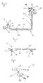
- Figure 1 shows a cross-sectional view of an assembled retail product display system according to the invention.
- the retail product display system comprises a shelf support track 1 adapted to be secured on a shelf, a demonstration product track 2 for receiving demonstration products and a communication track 3 for receiving labels.
- the shelf support track 1, the demonstration product track 2 and the communication track 3 have each the same cross-section throughout their respective length, but this is not necessary.
- the shelf support track 1 has a U-shaped cross-section defined by two substantially parallel leg members 5, 6 and a bottom part 7.
- the shelf support track 1 may be secured at a corresponding edge 4 of a shelf by inserting said edge 4 between the leg members 5, 6 till the bottom part 7 in a press-fit manner. Additionally or alternatively, the shelf may also be secured by means of screws or similar passing through one or both leg members 5, 6 and pressing on, or eventually passing through the shelf.
- the shelf support track 1 On the side of the bottom part 7 opposite to the two leg members 5, 6, the shelf support track 1 exhibits a longitudinal bead member 9 which comprises a rib 10 (best seen in fig.2). Said bead member 9 is preferably, but not necessarily, placed coplanar with the upper leg member 5. Said bead member 9 is rigidly linked to the shelf support track 1 via an arm part 8 which may be omitted.
- the shelf support track 1 On the side of the bottom part 7 opposite to the two leg members 5, 6, the shelf support track 1 also exhibits a wing member 11 linked to the underside of the arm part 8 and extending downwards away in a curved manner from said arm part 8 and from the bottom part 7.
- the wing member 11 may be directly linked to the bottom part 7 or to the leg members 5, 6 instead of arm part 8.
- the free end part 12 of said wing member 11 is substantially flat and perpendicular to the leg members 5, 6.
- Said wing member 11 is stiffened by an arm part 13 which links it to the bottom part 7, but such a stiffening may be omitted.
- Said wing member 11 may have any suitable form; in particular, it can be substantially planar.
- Said wing member 11 aims at abutting demonstration product track 2 at the end portion 12 as a shoulder, thus strengthening the retail product display system.
- the abutment of demonstration product track 2 on the wing member 12 may be omitted and hence, the wing member 11 may be omitted.
- the demonstration product track 2 has a general section of an L having a first arm 14 substantially perpendicular to a second arm 15.
- the inner face of the first arm 14, i.e. the face on the side of the second arm 15 is referenced 14a and the outer face of said arm 14, i.e. the face on the opposite side relatively to the second arm 15 is referenced 14b.
- the inner face of the second arm 15, i.e. the face on the side of the first arm 14 is referenced 15a and the outer face of said arm 15, i.e. the face on the opposite side relatively to the first arm 14 is referenced 15b.
- a longitudinal channel 16 is arranged at the free end part of arm 14 on the outer side 14b.
- Said longitudinal channel 16 engages the bead member 9 of the shelf support track 1, as will be detailed later with reference to fig.2.
- the face 14b may be in contact with the wing member 12. More precisely, the face 14b may abut the flat part end 12 of the wing member 11 of the shelf support track 1 with its end part opposite to the one carrying the channel 16.
- the inner face 15a of the second arm 15 is used as a shelf for receiving demonstration products (not shown) either directly or via a lining plate (not shown) adapted on the demonstration product track 2.
- a lining plate may be a L-shaped coloured plastic piece and arranged on both the inner face 15a and the inner face 14a of the demonstration product track 2 in a snap-in fashion. It is advantageous to use a lining plate for aesthetical reasons and eventually for adapting the position of the demonstration products.
- the free end part of second arm 15 is slightly raised upwards; this upraisal may be omitted.
- a longitudinal bead member 19 is arranged at the raised free end part of second arm 15 via an arm portion 21 (which may be omitted).
- the shape of the L-shaped link, constituted by the arms 14 and 15, between the channel 16 and the bead member 19 of the demonstration product track 2 may be modified, for example into a part of a circle.
- the communication track 3 comprises a member 22 having a curved section having a convex face 22a and a concave face 22b.
- a longitudinal channel 25 is arranged on one end part of said member 22 on its concave face 22b. Said longitudinal channel 25 slidably engages the bead member 19 of the demonstration product track 2, as will be detailed later with reference to fig.2.
- a hook-shaped member 23, 24 is arranged on each end part of said member 22 extending on the side of its convex face 22a.
- the concave part of both hook-shaped members 23, 24 are turned one toward the other.
- Labels (not shown), for instance labels with product information for clients, of a suitable height may be slid longitudinally on the convex face 22a and maintained by both hook-shaped members 23, 24. If they are sufficiently flexible, it is possible to insert said labels facially by squeezing them.
- the shelf support track 1, demonstration product track 2 and communication track 3 may be made, for example, from aluminium material and coated with a lacquer.
- End caps may be arranged on each extremity of shelf support track 1, demonstration product track 2 and communication track 3.
- an end cap may be arranged on each extremity of demonstration product track 2 in, for example, a press-fit manner which covers channel 16 and channel 25 in order to stop the possible longitudinal sliding movement of demonstration product track 2 relative to shelf support track 1 and of communication track 3 relative to demonstration product track 3: for that purpose, it is advantageous for shelf support track 1, demonstration product track 2 and communication track 3 to have the same length.
- the longitudinal bead member 9 of the shelf support track 1 has a circular section and exhibits a longitudinal rib 10 of semi-circular section extending in a direction substantially opposite to the leg members 5, 6 (but this position of the rib may be varied).
- the longitudinal channel 16 of the demonstration product track 2 has a circular shape and is open on a 90 large part 18 on the side opposite to the outer face 14a of the first arm 14.
- said 90 angle of the open part 18 may be varied with an upper limit approaching 180 , as it will result from the following.
- Four adjacent longitudinal grooves 17a, 17b, 17c, 17d having each a semi-circular section are arranged in a part of said channel 16 at the opposite side of its open part 18.
- the bead member 9 of the shelf support track 1 and its rib 10 are scaled for slidably engaging said channel 16 and its grooves 17a, 17b, 17c, 17d.
- the assembly of the demonstration product track with the shelf support track is possible by longitudinally sliding the bead member 9 of the shelf support track into the channel 16 of the demonstration product track 2 while the rib 10 engages one of grooves 17a, 17b, 17c, 17d and the arm part 8 passes through the open part 18.
- the passage in open part 18 of channel 16 is larger than the thickness of the arm part 8 linking the bead member 9 to the shelf support track 1 in order to allow said arm part 8 to extend through said open part 18 when the bead member 9 is positioned into the channel 16.
- the angle between the demonstration product track 2 and the shelf support track 1 can be selected by the user when mounting them together by engaging the rib 10 into a preferred one out of the four grooves 17a, 17b, 17c, 17d, each groove corresponding to another angle.
- groove 17a allows to assemble the demonstration product track 2 on shelf support track 1 in such a way that the arm 15 of the demonstration product track 2 is parallel to the leg members 5, 6 of the shelf support track 1.
- the three other grooves 17a, 17b, 17c allow to position the arm 15 at three different raised positions.
- the semi-circular shape of the rib 10 and of the corresponding grooves 17 may also be varied. Furthermore, it is also possible to change the general shape of bead member 9 and correspondingly the shape of channel 16 so long as their shape allows to engage slidably, but not rotatably, the bead member 9 with the channel 16.
- the link of communication track 3 with demonstration product track 2 by engagement of the bead member 19 and its rib 20 with the channel 25 and its grooves 26a, 26b, 26c, 26d, 26e is similar to the link described up-to-now of demonstration product track 2 with shelf support track 1 by engagement of the bead member 9 and its rib 10 with the channel 16 and its grooves 17a, 17b, 17c, 17d.
- everything said herein about shapes, mounting method and alternative embodiments made regarding the link between demonstration product track 2 and shelf support track 1 applies also to the link between communication track 3 and demonstration product track 2, and will not be repeated here.
- the link between communication track 3 and demonstration product track 2 is similar, it does not need to be identical with the link between demonstration product track 2 and shelf support track 1.
- the number of grooves in the channel 25 shown in fig. 1 is five (26a, 26b, 26c, 26d, 26e) instead of four (17a, 17b, 17c, 17d) for channel 16.
- demonstration product track 40 which is adapted for receiving a locator, especially a demonstration product locator 27 described in relation with fig.4.
- the demonstration product track 40 is identical to the demonstration product track 2 described in relation with fig. 1, except that means for receiving a locator have been added. So, demonstration product track 40 is adapted for being assembled with shelf support track 1 and communication track 3 described in relation with fig. 1. All references used on demonstration product track 2 are also used for demonstration product track 40 and correspond to the same parts.
- a first longitudinal U-shaped member 41 is arranged on the free end part of the first arm 14 on the inner face 14a.
- Said first U-shaped member 41 is defined by two substantially parallel leg members 42, 43 and a bottom part 44.
- a second longitudinal U-shaped member 45 is arranged on the raised free end part of the second arm 15 on the inner face 15a.
- Said second U-shaped member 45 is defined by two substantially parallel leg members 46, 47 and a bottom part 48. Both U-shaped members 41, 45 are arranged so that the open part of each are substantially facing each other.
- a demonstration product locator 27, not shown, including a plate may be inserted into the demonstration product track 40.
- the dimensions of the plate are such that the width allows the plate to be inserted between the U-shaped members 41, 45.
- the plate is first slidably inserted into U-shaped member 41, resting on the leg member 43. Then, the plate is caused to rest on leg member 47, and then slides down to bottom 48. Once mounted, the edges of the plate will abut on the leg members 46, respectively 42 if the plate is pulled in outside direction as the width of the plate is larger than the distance from bottom 48 to free end of leg member 41.
- leg member 42 is longer than leg member 46 while leg member 43, respectively 47 is preferably longer than leg member 42, respectively 46.
- demonstration product locator 27 which may be associated to a demonstration product track 40 of fig.3.
- the function of demonstration product locator 27 is to locate demonstration products on a demonstration product track 40.
- the demonstration product locator 27 is associated to the retail product display system in a covering relationship with demonstration product track 40 so that, when demonstration products are placed on the demonstration product track 40, said demonstration products may either extend or be reached with the fingers of the hand through openings made correspondingly in said demonstration product locator 27.
- demonstration product locator 27 comprises a plate member 28 which is shown flat, but may have various other shapes as, for example, curved. Openings 29 (only one can be seen) corresponding to the shape of the demonstration products are cut-out in the middle part of said plate member 28.
- a first longitudinal L-shaped member 30 is arranged on a first lateral region of said plate member 28.
- Said first L-shaped member 30 comprises a base part 31 extending substantially perpendicularly (but not necessarily) to the connecting face of said plate member 28. spaced from the plate member 28, preferably at the free end of said base part 31, a guide part 32 extends substantially parallel (but not necessarily) to the plate member 28 in the outward direction of said plate member 28.
- a second longitudinal L-shaped member 35 is arranged on the same face of the plate member 28 as the first L-shaped member 32, but in the lateral region opposite to the one of the first L-shaped member 30.
- Said second L-shaped member 35 comprises a base part 36 extending substantially perpendicularly (but not necessarily) to the connecting face of said plate member 28.
- a guide part 37 extends from said base part 36 substantially parallel (but not necessarily) to the plate member 28 in the outward direction of said plate member 28.
- Base part 36 may extend beyond the guide part 37 as a triangle-shaped part 38 for cooperating with the leg member 47 of demonstration product track 40. This part 38 may be omitted.
- Both longitudinal L-shaped members 30, 35 may be realised either continuously or in an interrupted manner on the whole length of the demonstration product locator 27.
- the demonstration product locator 27 can be obtained by injection moulding of plastic, or eventually by extrusion followed by cutting-out of the openings 29.
- the dimensions of the first U-shaped member 41 are adapted so that the guide part 32 of the first L-shaped member 30 of the demonstration product locator 27 may engage it.
- the dimensions of said second U-shaped member 45 are adapted so that the guide part 37 of the second L-shaped member 35 of the demonstration product locator 27 may engage it.
- the shape of the lower leg member 47 is the inverse of the triangle part 38 of the guide part 37 so to make possible the resting of the latter over its whole length on the leg member 47 when assembled.
- the two U-shaped members 41,45 are spaced so as to allow both the engagement of the first L-shaped member 30 into the first U-shaped member 41 and the engagement of the second L-shaped member 35 into the second U-shaped member 45.
- Mounting may be done by longitudinally sliding the demonstration product locator 27 onto the demonstration product track 40 while realising both engagements.
- this embodiment allows also to mount the demonstration product locator 27 in a facial way onto the demonstration product track 40 in the following way.
- the distance between the free end of the upper leg member 42 and the upper leg member 46 of the second U-shaped member 45 is smaller than the distance between the free end of the guide part 32 of the first L-shaped member 30 and the free end of the guide part 37 of the second L-shaped member 35.
- both engagements (and disengagements) at the same time by facial mounting.
- This mounting is similar to the mounting of the plate described in relation with fig.3.
- the first step consists in engaging the first L-shaped member 30 into the first U-shaped member 41, more particularly, by engaging guide part 32 between the two leg members 42, 43 substantially till abutment with the bottom part 44.
- the second step consists in lowering the guide part 37 of the second L-shaped member 35 from the outside onto the bottom leg 47 of the second U-shaped member 45 by passing the free end of the guide part 37 in front of the free end of the upper leg member 46 of the second U-shaped member 45.
- the abutment of the guide part 37 and its triangle-shaped part 38 onto the leg member 47 is facilitated due to the fact that leg member 47 is longer than leg member 46.
- the distance between the free end of the upper leg member 46 of the second U-shaped member 45 and the bottom part 44 of the first U-shaped member 41 i.e.
- the abutment surface, in first and second step of mounting, of the demonstration product track 40 with the demonstration product locator 27 is at least equal to the distance between the free end of the guide part 37 of the second L-shaped member 35 and the free end of the guide part 32 of the first L-shaped member 30 (i.e. the abutment surface, in first and second step of mounting, of the demonstration product locator 27 with the demonstration product track 40).
- the distance between the free end of the upper leg member 46 and the bottom part 44 be very slightly smaller than the distance between the free end of guide parts 32 and 37: this allows an insertion by using the resilient characteristics of the materials of the demonstration product locator 27 and demonstration product track 40 (the resilient characteristics are than providing advantageously a supplementary security for avoiding accidental disassembling of the demonstration product locator 27 from the demonstration product track 40).
- the third step consists in sliding the guide part 37 of the second L-shaped member 35 between the leg members 46, 47 of the second U-shaped member 45 till abutment of the free end of guide part 37 with the bottom part 48 and/or covering of the shape of leg member 47 by the matching shape of the guide part 37 and the triangle-shaped part 38. In fact, the sliding in the third step is done automatically due to the weight force of the demonstration product locator 27. Insertion is facilitated by the triangle-shaped part 38 gliding on upper leg member 46.
- the distance between the free end of guide part 32 and the free end of guide part 37 i.e. the abutment surface, when assembled, of the demonstration product locator 27 with the demonstration product track 40 on the side of the second U-shaped member 45
- the distance between free end of leg member 42 and the bottom part 48 i.e. the abutment surface, when assembled, of the demonstration product track 40 with the demonstration product locator 27 on the side of the second U-shaped member 45.
- the demonstration product locator 27 may be removed facially by firstly sliding demonstration product locator 27 towards the first U-shaped member 41 so that the guide part 32 of the first L-shaped member 30 abuts on the bottom part 44 of the first U-shaped member. Secondly, the guide part 37 of the second L-shaped member 35 is pulled up from the bottom leg member 47 of the second U-shaped member 45 out of the region of the second U-shaped member 45 by passing the free end of the guide part 37 in front of the free end of the upper leg member 46 of the second U-shaped member 45. The last step consists in sliding the demonstration product locator 27 so as to disengage the guide part 32 from the first U-shaped member 41.
- the manner of cooperating of the L-shaped members 30, 35 with the U-shaped members 41, 45 may be varied by changing the dimensions of these organs. For example, during first and secons step of mounting, it has been described that the free end of guide part 32 of first L-shaped member 32 substantially abuts the bottom part 44 of first U-shaped member 41; instead, it is possible to change dimensions so it is the free end of leg member 42 that abuts base part 36.
- demonstration product locator 27 when demonstration product locator 27 is mounted on demonstration product track 40, it has been described that the free end of guide part 37 abuts bottom part 48 and/or guide part 37 with triangle-shaped part 38 cover matching shape of leg member 47; instead, it is possible to change dimensions so it is the free end of leg member 46 that abuts base part 36.
- a further example is that, once mounted, the demonstration product locator 27 rests on the demonstration product track 40 by abutment of the guide parts 32, 37 on respectively the leg members 43, 47; instead, it is possible to change dimensions so that it is plate member 28 that abuts on the outward face of leg members 42, 46.
- leg members 43, 47 may then be omitted: the L-shaped members 30, 35 are completed by the plate member 28 so as to define U-shaped members which are engaged by leg members 42, 46.
- the embodiment described in relation with fig.4 has several advantages compared to the previously existing systems.
- the rails i.e. the U-shaped members 41, 45
- the width of the demonstration product locator 27 is no more limited to the distance between both rails.
- all members that may be arranged on the demonstration product locator 27, as, for example, a seat member for the pivot axle of a closing cover, may be situated out of the region in which openings may be arranged for locating demonstration products.
- the location for demonstration products on the demonstration product locator may consist in a recess arranged on the plate member 28 extending over the U-shaped members 41, 45, thereby allowing the placement of demonstration products larger than the distance between said two U-shaped members 41, 45. It is particularly preferred to use a plate member 28 with appropriate thickness, i.e. a sufficiently large thickness so to allow said recess to have significant depth for providing good positioning of demonstration products.
- the demonstration product locator, now referenced 49 is identical, in particular as regards shapes and dimensions, to the demonstration product locator described in relation with fig.4, except for the guide part 32 of first L-shaped member 30.
- the demonstration product locator 49 shown in fig.5 comprises a modified guide part now referenced 33.
- a guide part 33 extends parallel to the plate member 28 in the outward direction of said plate member 28.
- the thickness in the direction of the free end of the guide part 33 diminishes abruptly by forming a face 34a substantially perpendicular to the guide part 33 so as to form a step-shaped guide part 34, said step-shaped part 34 being realised on the side of the guide part 33 facing away from the plate member 28.
- the total length of the guide part 33, including the step-shaped part 34 is identical to the length of the guide part 32 in the embodiment of fig.4.
- the thickness of the guide part 33 before its step-shaped part 34 is identical to the thickness of the guide part 32 in the embodiment of fig.4.
- the way of mounting the demonstration product locator 49 onto demonstration product track 40 is similar to the way described in reference with fig.3 and 4, the reference to the guide part 32 being replaced with the reference to the guide part 33, including its step-shaped part 34.
- the first L-shaped member 30 rests on the bottom leg member 43 with exclusively the step-shaped part 34 and face 34a is adjacent to the free end of inner leg member 43.
- this embodiment has the advantage of diminishing the transversal floating of the demonstration product locator 49 in the demonstration product track 40.
- This transversal floating in embodiment of fig.4, is due to the fact that the distance between the free end of the guide parts 32, 37 of the L-shaped members 30, 35 is smaller than the distance between the bottom parts 44, 48 of the U-shaped members 41, 45 as it results from the description of said embodiment.
- the embodiment of fig.5 diminishes greatly this transversal floating because, if an effort to slide the demonstration product locator 49 in the direction of the first U-shaped member 41 occurs, the face 34a of the guide part 33 will abut on the free end of the inner leg member 43 and so limit the movement.
- the facial disassembling of the demonstration product locator 49 from demonstration product track 40 is more complicated compared to the embodiment of fig.4.
- the first step consists in pulling demonstration product locator 49 so that guide part 33 of the first L-shaped member 30 abuts the upper leg member 42 of the first U-shaped member 41. At this moment, face 34a of guide part 33 does no longer abut on the free end of the inner leg member 43. So, it becomes possible to slide demonstration product locator 49 towards the first U-shaped member 41 so that the guide part 33 via its step-shaped part 34 abuts on the bottom part 44 of the first U-shaped member 41.
- the disassembling is continued in the same manner as for the embodiment of fig.4.
- the facial disassembling of demonstration product locator 49 from demonstration product track 40 is more complicated compared to the embodiment of fig.4; this is an advantage as it further diminishes the risk of undesired removal of the demonstration product locator 49 from the demonstration product track 40 by consumers in a shop.
- Fig.6 is a schematic view showing a cross-section of a part of a retail product display system having a demonstration product track 40 with an associated demonstration product locator 49 of the type described in fig.5.
- the demonstration product locator 50 is identical, in particular as regards shapes and dimensions, to demonstration product locator 49 described in relation with fig.5, except for the base part 31 of the first L-shaped member 30.
- the modification may also be done on the demonstration product locator 27 of the embodiment of fig.4.
- the demonstration product locator 50 may be used on the same retail product display system as the demonstration product locator 49, in particular, demonstration product locator 50 may be mounted on the demonstration product track 40 described in relation with fig.3. All references used for describing demonstration product locator 49 are also used for demonstration product track 50 and correspond to the same parts.
- the modified base part 31 of demonstration product locator 49 which is longer and comprises an extended part 52 (but the guide part 33 is arranged at the same distance relatively to the plate member 28).
- a demonstration product support 51 is arranged with a first wall 53 onto the base part 31 of the first U-shaped member on the side opposite to the guide part 33. Due to the increased length of the base part 31 up to the extended part 52, an efficient securing, by means of glue or screws or similar, of wall 53 of the demonstration product support 51 onto the base part 52 becomes possible. Of course, the length of base part 31 may not be increased if it offers sufficient surface for allowing an efficient securing of wall 53.
- the demonstration product support 51 is constituted by a plate member presenting two folds forming two opposite walls 53, 55 linked by a bottom wall 54. Once the demonstration product support 51 is associated onto demonstration product locator 50, demonstration product support 51 extends partly through a corresponding opening 29 of demonstration product locator 50.
- a longitudinal notch 54a may be arranged on the bottom wall 54 of the demonstration product support 51, said notch 54a cooperating with the edge of the opening 29 laying opposite to the first L-shaped member 30 in order to improve the securing of the demonstration product support 51 on the demonstration product locator 28.
- the bottom wall 54 may be substantially horizontal so that demonstration products may be placed on it.
- the length of the demonstration product support 51 and of the corresponding opening 29 can be variable. It is of course possible to arrange several demonstration product supports 51 through several corresponding openings 29 arranged longitudinally onto demonstration product locator 50 in spaced relationship.
- the demonstration product locator 57 is identical, in particular as regards shapes and dimensions, to demonstration product locator 27 described in relation with fig.4, except for the free end part of the plate member 28 on the side of the first L-shaped member 30.
- the modification may also be done on all other described embodiments of the demonstration product locator, in particular demonstration product locator 49 of fig.5 or demonstration product locator 50 of fig.7.
- the demonstration product locator 57 may be used on the same retail product display system as the demonstration product locator 27, in particular, demonstration product locator 50 may be mounted on the demonstration product track 40 described in relation with fig.3.
- Unchanged references used in relation with fig.8 designate the same parts as referred to in previous figures.
- For demonstration product locator 57 we will only describe here the modified end part of the plate member 28 of demonstration product locator 27 for obtaining demonstration product locator 57.
- a rectangular recess 64 is arranged on the end part of the plate member 28 on the side of and on the same face that the first L-shaped member 30. Two opposite face of said recess extend longitudinally.
- the recess may have another shape, for example, a circle.
- the hole may be obtained by punching-out or by means of laser cutting.
- a seat member 56 (or bridge member) is arranged in hole 65 and recess 64.
- the seat member 56 comprises two leg members 58, 60 facing each other in spaced relationship and which are linked at one end thereof by an annular part 62. Foot members 59, 61 are arranged on the opposite end of each of said leg members 58, 60, said foot members 59, 61 facing away from each other.
- the seat member 56 is made of plastic for instance and the leg members are resilient. The seat member 56 is engaged through the hole 65 by pinching together both leg members 58, 60 and inserting them through the hole 65 until both foot members 59, 61 extend into the recess 64.
- each leg member 58, 60 presses against a respective side of the hole 65 for firmly maintaining the seat member 56 onto the plate member 28.
- the foot members 59, 61 engage with the bottom of the recess 64 in order to prevent said seat member from sliding out of the hole 65.
- the height of said foot members 59, 61 is smaller than or equal to the depth of said recess 64, to prevent them from extending outside the plate member 28. This will allow placing seat members 56 at an upper location of the plate member 28, thus extending the space dedicated to product demonstration.
- each leg member 58, 60 exhibits, on its external face, a shoulder 66, 67 abutting said plate member 28 so as to prevent the seat member 56 from sliding through the hole 65 in the direction of the recess 64.
- the foot members 59, 61 will not extend outside of plate member 28 and so, said foot members 59, 61 may not obstruct the mounting of the demonstration product locator 57 onto the demonstration product track 40 because of contacting parts of said demonstration product track, in particular the first U-shaped member 41. Shoulders 66, 67 may be avoided if foot members 59, 61 abut on e.g. the U-shaped member 41.
- the hollow 63 defined by the internal face of the annular part 62 is substantially circular and its axis is longitudinal.
- a second seat member 62 (not shown) is arranged on the plate member 28 by engagement through a second hole 65 and recess 64 (not shown) in longitudinal spaced relationship with the first seat member 56, but the axis of the hollows 63 being identical.
- a pivot axle (not shown) through said hollows 63 on which may be articulated a cover (not shown) the purpose of which is to close a corresponding opening 29 of the plate member 28.
- the rotation of said cover may be limited by an external shoulder 71 arranged on the top of the annular part 62.
- Such an articulated cover is particularly advantageous when the demonstration product accessible through said opening 29 consists in a powder because the powder is protected against draughts.
- several recesses 64 are arranged in a longitudinal direction and in spaced relationship on the demonstration product locator 57 which define as many possible locations for seat members 56. According to the need of seat members 56 depending on the use of the demonstration product locator, through holes 65 will subsequently be formed at only certain of said recesses 64.
- the seat members were moulded in one piece with the demonstration product track with the aesthetical drawback of exhibiting possibly unused seat members when no articulated cover is desired.
- This embodiment alleviates this drawback by leaving the choice to the user whether or not to associate seat members onto the demonstration product track.
- the demonstration product locator 68 is identical, in particular as regards shapes and dimensions, to demonstration product locator 27 described in relation with fig.3, except for the free end part of the plate member 28 on the side of the first L-shaped member 30.
- the modification may also be done on all other described embodiments of the demonstration product locator, in particular demonstration product locator 49 of fig.5, demonstration product locator 50 of fig.7 and demonstration product locator 57 of fig.8.
- the demonstration product locator 68 may be used on the same retail product display system as the demonstration product locator 27, in particular, demonstration product locator 68 may be mounted on the demonstration product track 40 described in relation with fig.4.
- Unchanged references used in relation with fig.9 designate the same parts as referred to in previous figures.
- For demonstration product locator 68 we will only describe here the modified end part of the plate member 28 of demonstration product locator 27 for obtaining demonstration product locator 68.
- a longitudinal notch 69 is arranged in the end part of the plate member 28 corresponding to the first L-shaped member 30 and situated on the face opposite to the latter.
- the notch 69 has a V-shaped section defined by two walls 74, 75 linked by a restrained bottom part.
- the wall 74 which is the nearest to the end of the plate member 28, is inclined towards the nearest end of plate member 28 from the bottom part on.
- the other wall 75 is substantially perpendicular to the main faces of the plate member 28.
- the end 78 of the plate member 28 near the notch 69 is slightly curved and meets the face of the plate member 28 opposite of the one having the notch 69 with another notch 70.
- a label support 79 is arranged onto said end 78.
- Said label support 79 is defined by two leg members 72, 73 facing each other and linked by a rounded part on one of their respective ends.
- Said label support 79 is made of, e.g. transparent resilient plastic. Its two leg members resiliently press against one another.
- First leg member 72 is substantially straight.
- Said second leg member 73 is defined by a first part 76 which is linked at one end to the first leg member via the rounded part.
- Said first part 76 joins a second part 77, the shape of which is the inverse of the shape of the end 78, notch 70 included, of the plate member 28.
- the label support 79 is mounted onto the end 78 of the plate member 28 by snapping the first leg member 72 into the notch 69 and the second part 77 of the second leg member 73 around the end 78 so that the free end of said second part 77 engages the notch 70.
- the first leg member 72 will rest along the inclined wall 74.
- the space between said first leg member 72 and the first part 76 of said second leg member 73 may receive a corresponding label.
- the label may be inserted longitudinally or by slightly separating the two leg members 72, 73 and passing it between the latter (before mounting it on the plate member 28, in the latter case).
- the label support 79 When mounted onto demonstration product locator 68, the label support 79 extends upwardly with respect to the latter so that consumers may read the labels when the retail product display system, including said demonstration product locator 68, is secured on a shelf edge 4.
- the shapes of the label support 79 as well as the end 78 of the demonstration product locator 68 may be varied.
- This embodiment is advantageous because it allows to fit labels on another location of the retail product display system than its communication track; this possibility did not exist in the past. So, it makes information clearer for consumers.
- it allows to use one series of labels for unvarying data about the products, as for example, the name of the product and technical information about it, which will be placed on the communication track 3 and a second series of labels for data that changes more often in time, as for example, the price of the product, which will be placed on label supports 79.
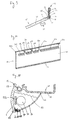
- Demonstration product locator 80 comprises a flat shaped member 28 and a first longitudinal L-shaped member 30 with three interruptions so that it defines four longitudinal L-shaped parts 30a, 30b, 30c, 30d.
- Demonstration product locator 80 comprises two seat members on each extremity, moulded in one piece with the plate member 28.
- Demonstration product locator 80 further comprises three recesses 64a, 64b, 64c for optionnaly receiving additional seat members 56 (not shown).
- Each recess 64a, 64b, 64c is preferably arranged (partly) between two consecutive L-shaped parts, respectively 30a, 30b; 30b, 30c; 30c, 30d.
- Said additional seat members 56 have, when mounted, the same axis as the seat members 55a and 55b in order to be used together for receiving a pivot axle on which a cover is articulated (not shown).
- the distance between the extremity of the plate member 28 at the side of seat member 55a and a location between the second L-shaped part 30b and the first recess 64a corresponds to one of what will be called a "Plé unit" (one Plé unit is equal to about 78 mm); a small transversal groove 81a may be present at this location.
- the distance between said location identified by the small groove 81a and a location between the third L-shaped part 30c and the second recess 64b corresponds to a half Plé unit and is identified here by a small transversal groove 81b.
- the distance between said location identified by the small groove 81b and the location identified by the small groove 81c corresponds a half Plé unit.
- the distance between said location identified by the small groove 81c and the extremity of the plate member 28 at the side of seat member 55b corresponds to a half Plé unit.
- the demonstration product locator 80 may be cut into sub-elements of selected length.
- the first possibility is to cut the demonstration product locator 80 transversely at the level of the first groove 81a.
- the demonstration product locator 80 has then a length of one Plé unit comprising the first seat member 55a and the first recess 64a adapted to receive a removable seat member 56, and hence, it is possible to fit the pivot axle of a cover on them.
- the second possibility is to cut the demonstration product locator 80 transversely at the level of the second groove 81b.
- the demonstration product locator 80 has then a length of 1,5 Plé unit comprising the first seat member 55a and the second recess 64b adapted to receive a removable seat member 56 and hence, it is possible to fit the pivot axle of a cover (which may be larger as in the first variant) on them.
- the remaining parts, after cutting, may also be used as demonstration product locator.
- the cutting out may be done, for example, by means of a cutting disc or a laser beam.
- the fact that the first L-shaped member 53 is interrupted at each end of full Plé and half Plé parts facilitates the cutting.
- demonstration product locator 80 may be used with its full length without cutting it into sub-elements. Alternately, it is also possible to omit seat members 55a and 55b and replace them with recesses 64 adapted to receive removable seat members 56.
- demonstration product locator 80 may be mounted adjacent on a same demonstration product track 40 according to the wish of the user.
- the length of the small grooves 81a, 81b, 81c may be limited or, on the contrary, extend over substantially the whole width of the demonstration product locator. In the latter case, said grooves may also be deep enough to obtain a divisible demonstration product locator. Of course, other kind of marks may be used. Said grooves may also be absent.
- the advantage of the embodiment described in relation with fig. 10 is to limit down to one the number of molds necessary to produce demonstration product locators of different lengthes in a simple manner.
- Fig. 11 shows a cross-section of a part of a retail product display system comprising a lighting tube 91, for example, of the neon type, and its support 90 as well as a glass screen 86, preferably a frosted glass screen.
- the retail product display system is similar to any one of those described up-to-now; in particular, fig. 11 shows a demonstration product track 40 of fig.3 and a communication track 3 of fig. 1.
- the lighting tube 91 extends longitudinaly on the concave side of the communication track 3.
- the ligthing tube 91 is held by an associated longitudinal support 90 held on communication track 3.
- the lighting tube 91 and its support 91 may be a standard type available in the trade and their length is preferably a bit shorter than communication track 3.
- Said support 90 is secured onto communication track 3 by various means, such as via end caps, as it will be described in relation with fig. 12.
- the glass screen extends from the end region of the communication track 3 (near the hook-shaped member 23) to the demonstration product track 40. It can extend over substantially the whole width of said demonstration product track 40 or only a part thereof, as shown.
- a longitudinal hinge member 84 made, for example, of plastic, is arranged on the bottom end of communication track 3 by means, for example, of glue.
- Said hinge member 84 exhibits a channel 85 which is open in a direction substantially perpendicular to the concave face 22b or eventually in an upward direction.
- Said hinge member 84 engages with a longitudinal frosted glass screen 86 which diffuses the light of the lighting tube 91.
- the lighting tube 91 and its support 90 are located between the communication track 3 and the frosted glass screen 86.
- Said frosted glass screen 86 has a curved cross-section.
- One or several springs 89 are secured by one end onto the upper end part 87 region of frosted glass screen 86, on its concave face.
- the opposite end 88 of frosted glass screen 86 is shaped so that it may fit in the channel 85 of the hinge member 84 arranged on communication track 3.
- spring 89 is secured on communication track 3 near the region of its channel 25.
- the spring 89 maintains the frosted glass screen 86 in its engagement position in channel 85 and causes the end 87 of said frosted glass screen to abut on second arm 15 of the demonstration product track 40.
- the rotatable engagement of the hinge member with the end 88 of the frosted glass screen may be obtained with various other means.
- the hinge member 84 may also be obtained in one piece with communication track 3.
- the ballast (not shown) of the lighting tube 91 is preferably not secured onto communication track 3 because it is usually relatively voluminous.
- Said ballast may advantageously be fitted under the shelf support track of the corresponding retail product display system or on some appropriate location under the shelf on which the latter is secured.
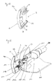
- Fig. 12 shows one extremity of the communication track 3 of fig. 11.
- An end cap 82 made, for example, of plastic or aluminium, is arranged on the extremity of communication track 3.
- the end cap is secured on communication track 3 in a press-fit manner by pinching resiliently the extremity of communication track 3 between a tab 83 on the concave face 22b of communication track 3 and one other tab part (not shown) on the convex face 22a of communication track 3.
- a second end cap of the 82 type, but symetrical, is engaged on the opposite extremity of communication track 3.
- the tab 83 of both end caps 82 are used to secure, by means of glue, screws or similar, the support 90 (not shown) and its lighting tube 91.
- the support 90 may also simply be maintained in press-fit manner between communication track 3 and tab 83.
- Fig.13 shows one extremity of the communication track 3 of fig.1.
- the channel 25 has not been represented (it would be on the upper part of communication track 3 as shown in fig. 12).
- An end cap 96a is arranged on the extremity of the communication track 3.
- Another end cap 96b (not shown), similar but symetrical, is arranged on the other extremity of the communication track 3.
- the comments will be limited to the side of end cap 96 as the comments for the side of the opposite end cap are identical.
- the end caps 96a, 96b are used for securing the longitudinal support 90 (not shown, see fig. 11) for the lighting tube 91 and the frosted screen 107.
- no hinge member (as hinge member 84 of fig. 11) has to be arranged directly on communication track 3.
- the end cap 96a is secured on communication track 3 in a press-fit manner by pinching resiliently the extremity of communication track 3 between a tab 97 on the concave face 22b of communication track 3 and a tab part (not shown) on the convex face 22a of the communication track 3.
- the free end of tab 97 exhibits a part 98 extending substantially perpendiculary to the communication track 3 in a direction opposite to the communication track 3, i.e. tab 97 with part 98 form a L-shaped member.
- a first hole is arranged in tab 98 with an axis parralel to communication track 3.
- a screw 99 is arranged through said hole and the head of said screw 99 rests on tab 98 on the side of the extremity of the communication track 3.
- Said screw 99 is used to secure the longitudinal support 90 for the lighting tube 91.
- Said extremity 103 is extended by a longitudinal tab 101.
- the free end of said tab 101 exhibits a part 102 extending away from communication track 3 in a substantially perpendicular fashion, i.e. tab 101 with part 102 form a L-shaped member.
- Tab 102 has a threaded hole cooperating with the threaded part of screw 99.
- the longitudinal support 90 is held by the end caps 96a, 96b through one screw 99 at each extremity.
- the longitudinal frosted screen 107 has the same general shape as screen 86 in fig. 11.
- screen 107 has a longitudinal bead member 100 arranged on its edge on the side of communication track 3, in the extremity region.
- the length of said bead member 100 is limited compared to the length of the whole screen 107.
- a longitudinal hole is arranged through said bead member 100.
- a transversal portion of said bead member 100 and a further part of screen 107 are removed, either through the moulding itself or by cutting out. Said transversal portion is slightly larger than the thickness of tab 98.
- a first leg member 106a of spring 106 pushes against the outer wall of screen 107 and the second leg member pushes against the concave face 22b of communication track 3.
- said spring 106 pushes screen 107 in direction of demonstration product track so that the edge of said screen 107 abuts said demonstration product track (as shown in embodiment of fig. 11).
- bead member 100 may be realised on the whole length of screen 107.
- the longitudinal hole in said bead member 100 may then have a limited length on each extremity region of screen 107 and be threaded for receiving screw 104.
- spring 106 may be omitted.
- the spring function for pushing screen 107 against product demonstration track is obtained through screen 107 itself, as it may be taken from fig. 14.
- fig. 14 shows only a part of end cap 96a and screen 107.
- a longitudinal wing member 107a is arranged on longitudinal bead member (which is preferably arranged on the whole length of screen 107) on the side opposite to screen 107.
- Screen 107 is mounted on end caps 96a, 96b in the same manner than previously, i.e. a transversal portion is cut out from bead member 100 and screen 107 as well as wing member 107a in order to receive tab 98 and the whole is maintained with a screw 99.
- wing member 107 When mounted, wing member 107 abuts on the concave face 22b of communication track 3 and as a result screen 107 is rotated upwardly against demonstration product track. By varying the angle of communication track 3 with the demonstration product track, screen 107 continue to abut on the demonstration product track due to the resilient characteristic of the plastic material used for screen 107.
- fig. 13 and fig. 14 are particularly advantageous as they can easily be adapted on existing retail product demonstration track without any modifications or adaptation of its main parts, in particular, the communication track. There is not even a hinge member to add on communication track as it is the case in fig. 11 and fig. 12.
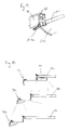
- Fig. 15 is a side view showing three shelves 92a, 92b, 92c in superposed relationship, each having a retail product display system repectively referenced 93, 95a, 95b comprising an illumination system secured on its edge.
- lighting systems were secured under the shelf in order to illuminate the retail product display system located on the shelf underneath.
- Such an illumination system 94 equips the retail product display system 93 of the upper shelf 92a.
- This system has a drawback consisting in the fact that only the underlying shelf 92b is well illuminated, but the communication track as well as the demonstration products on the demonstration product track of the associated retail product display system 95a are only poorly illuminated, particularly in the case of fig. 15 where the underlying shelf 92b is larger than shelf 92a (for visual commodity of clients).
- the remedy to this problem consisting in increasing the power of the lighting system is not convenient because it increases the power consumption and emits more heat so that underlying products may be damaged and hands of clients may be heated or burned.
- the embodiment of fig. 11 to fig. 14 alleviates these drawbacks as the lighting system supported by communication track is located in the region above the communication track of the underlying retail product display system even if the underlying shelf is larger, at least if the difference of width is kept within appropriate limits. This result can be seen on fig. 14 with retail product display system 95a (as well as retail product display system 95b) which corresponds to any one of embodiment of fig.11 to fig. 14.
- the illumination system of retail product display system 95a illuminates the shelf 92c, the demonstration product track of retail product display system 95b as well as the communication track of the latter.
- the invention is not limited to the embodiments described.
- the demonstration product locator and lighting system according to the invention may well be mounted on other existing retail product display systems, if needed.
Landscapes
- Display Racks (AREA)
Abstract
The invention provides a retail product display system, including a shelf support track,
a demonstration product track and a communication track, said tracks being linked with
each other through engagement means comprising bead members with ribs and
matching means comprising channels and grooves, where said engagement means and
matching means engage slidably, at selected angles, thereby preventing rotation thereof.
The invention also provides a demonstration product locator as well as a longitudinal
lighting element.
Description
- The invention relates to a retail product display system, more particularly, to a retail product display system exhibiting demonstration products as, for example, cosmetics, and associated information destined to be seen by consumers in shops, the retail product display system being adapted to be secured on shelves.
- Retail product display systems are already known. Some of them consist in a demonstration product track for receiving demonstration products, on one end of which is arranged a communication track for receiving labels. The demonstration product track is secured on a shelf by the opposite end. However, these retail product display systems have several drawbacks. A first drawback consists in the fact that neither the angle between the demonstration product track and the shelf nor the angle between the demonstration product track and the communication track are selectable. So, it is not possible to adapt the relative position of these parts of the retail product display system in order to optimize its ergonomy for consumers.
- Such retail product display system are often used with an associated demonstration product locator consisting in a flat member exhibiting openings for receiving corresponding demonstration products, the demonstration product locator being placed in covering relationship with the demonstration product track. The demonstration product locator is usually maintained by sliding two opposite edges thereof into rails arranged on the demonstration product track. This system has several drawbacks. First, the rails, which may be unaesthetic, are partly visible to consumers. Secondly, the width of the demonstration product locator is limited to the distance between both rails and all members that may be arranged on the demonstration product locator, as, for example, a seat member for the pivot axle of a closing cover, are necessarily situated in the region which may be used for locating the demonstration products, thereby limiting the space available for the latter.
- Another drawback consists in the fact that consumers in shops can release the demonstration product locator from the demonstration product track with relative ease, this possibility being obviously not desired.
- For small or flat demonstration products, a demonstration product support is often added to the demonstration product locator which allows to position those products on a higher level instead of placing them directly onto the demonstration product track. So, these demonstration products are at the same sight level for consumers as more bulky ones. A demonstration product support usually consists in a plate member with three folds which form four faces. One end face is used to secure it onto the plate member of the demonstration product locator while the other faces forms a repository for the demonstration products, said repository passing partly through an opening of the demonstration product locator. A drawback consists in the difficulty of producing demonstration product supports having three folds and the cost incurred.
- Seat members are usually arranged on the outside of the demonstration product locator which may receive pivot axles of covers for closing openings locating demonstration products. A drawback consists in the fact that several seat members may be left free, i.e. without pivot axles of covers resulting in an unaesthetic effect since they are visible to consumers.
- A further drawback consists in that all information about the demonstration products is contained on labels placed on the communication track. It is advantageous if labels could also be fitted at another location because it could make the information clearer for consumers. It would also allow to use one series of labels for data about the products that rarely changes, as for example, the name of the product and technical information about it and a second series of labels for data that changes from time to time, as for example, the price of the product.
- Demonstration products for display on the retail product display system may be of variable size and shapes, and accordingly, several kinds of demonstration product locators may be needed. A drawback consists in that it is usually necessary to provide a separate mold for each kind of demonstration product locator, and as a result, increased cost linked to these moulds.
- Furthermore, such retail product display system are often equipped with an illumination system, usually secured under the shelf support track in order to illuminate the demonstration products of a second retail product display system secured on an underlying shelf and the products on this shelf extending beyond this second retail product display system. The drawback consists then in the fact that the communication track of the second retail product display system is poorly illuminated, especially if the underlying shelf is larger than the first one, and hence, reading information on the labels on the communication track may be less easy and the shelves are less attractive.
- It even happens that the demonstration product track is badly illuminated so that colours of product packages are not appreciated by consumers. However, it is not possible to increase the light power since this would imply high temperatures of the products, possibly degrading some of them and preventing customers from taking the hot products out from the shelf.
- It is an aim of the present invention to alleviate, at least partly, the above mentioned drawbacks.
- The invention relates to a retail product display system, including a shelf support track, a demonstration product track and a communication track, said tracks being linked with each other through engagement means comprising bead members with ribs and matching means comprising channels and grooves, where said engagement means and matching means engage slidably, at selected angles, thereby preventing rotation thereof. According to one embodiment, the retail product display system comprises a demonstration product locator according to any of
claims 2 to 8. - According to another embodiment, the retail product display system comprises a lighting system according to any of
claims 9 to 11. - A retail product display system embodying the invention will now be described, by way of a non-limiting example, with reference to the accompanying drawings, in which:
- figure 1 is a schematic view showing a cross-section of an assembled retail product display system according to the invention;
- figure 2 is an enlarged partial exploded view of the link between the shelf support track and the demonstration product track of the retail product display system shown in figure 1;
- figure 3 is a schematic view of a demonstration product track similar to the one shown in figure 1, but modified for receiving a demonstration product locator such as the one shown in figure 4;
- figure 4 is a schematic view showing a cross-section of a demonstration product locator adapted for being mounted on the demonstration product track of fig.3;
- figure 5 is a schematic view showing a cross-section of a part of demonstration product locator according to another embodiment of the invention;
- figure 6 is a schematic view showing a cross-section of a part of a retail product display system having a demonstration product track with an associated demonstration product locator of fig.5;
- figure 7 is a schematic view showing a cross-section of a
demonstration product locator 50 with an associated demonstrationproduct support frame 51 according to another embodiment of the invention; - figure 8 is a schematic view showing a cross-section of a part of a demonstration product locator according to another embodiment of the invention;
- figure 9 is a schematic view showing a cross-section of a part of a demonstration product locator according to another embodiment of the invention;
- figure 10 is a schematic view showing in perspective a demonstration product locator according to another embodiment of the invention;
- figure 11 is a schematic view showing a cross-section of a part of a retail product display system according to another embodiment of the invention and which comprises a lighting tube and a frosted glass screen;
- figure 12 is a schematic view showing in perspective one end of a communication track on which is arranged an end cap used for securing the illumination system of fig.11;
- figure 13 is a schematic view showing in perspective an end cap used for securing the illumination system of fig. 11 and the corresponding frosted glass screen;
- figure 14 is a schematic view of a part of a frosted screen articulated on an end cap for communication track;
- figure 15 is a schematic side view showing three shelves in superposed relationship, each having a retail product display system comprising an illumination system, secured on its edge, two illumination systems being according to the embodiments of fig. 11 to fig. 14 and one according to the prior art.
- Figure 1 shows a cross-sectional view of an assembled retail product display system according to the invention.
- The retail product display system comprises a
shelf support track 1 adapted to be secured on a shelf, ademonstration product track 2 for receiving demonstration products and acommunication track 3 for receiving labels. In this embodiment, theshelf support track 1, thedemonstration product track 2 and thecommunication track 3 have each the same cross-section throughout their respective length, but this is not necessary. - The
shelf support track 1 has a U-shaped cross-section defined by two substantiallyparallel leg members 5, 6 and abottom part 7. Theshelf support track 1 may be secured at a corresponding edge 4 of a shelf by inserting said edge 4 between theleg members 5, 6 till thebottom part 7 in a press-fit manner. Additionally or alternatively, the shelf may also be secured by means of screws or similar passing through one or bothleg members 5, 6 and pressing on, or eventually passing through the shelf. - On the side of the
bottom part 7 opposite to the twoleg members 5, 6, theshelf support track 1 exhibits alongitudinal bead member 9 which comprises a rib 10 (best seen in fig.2). Saidbead member 9 is preferably, but not necessarily, placed coplanar with theupper leg member 5. Said beadmember 9 is rigidly linked to theshelf support track 1 via an arm part 8 which may be omitted. - On the side of the
bottom part 7 opposite to the twoleg members 5, 6, theshelf support track 1 also exhibits a wing member 11 linked to the underside of the arm part 8 and extending downwards away in a curved manner from said arm part 8 and from thebottom part 7. The wing member 11 may be directly linked to thebottom part 7 or to theleg members 5, 6 instead of arm part 8. Thefree end part 12 of said wing member 11 is substantially flat and perpendicular to theleg members 5, 6. Said wing member 11 is stiffened by anarm part 13 which links it to thebottom part 7, but such a stiffening may be omitted. Said wing member 11 may have any suitable form; in particular, it can be substantially planar. Said wing member 11 aims at abuttingdemonstration product track 2 at theend portion 12 as a shoulder, thus strengthening the retail product display system. However, the abutment ofdemonstration product track 2 on thewing member 12 may be omitted and hence, the wing member 11 may be omitted. - The
demonstration product track 2 has a general section of an L having afirst arm 14 substantially perpendicular to asecond arm 15. The inner face of thefirst arm 14, i.e. the face on the side of thesecond arm 15 is referenced 14a and the outer face of saidarm 14, i.e. the face on the opposite side relatively to thesecond arm 15 is referenced 14b. The inner face of thesecond arm 15, i.e. the face on the side of thefirst arm 14 is referenced 15a and the outer face of saidarm 15, i.e. the face on the opposite side relatively to thefirst arm 14 is referenced 15b. Alongitudinal channel 16 is arranged at the free end part ofarm 14 on the outer side 14b. Saidlongitudinal channel 16 engages thebead member 9 of theshelf support track 1, as will be detailed later with reference to fig.2. The face 14b may be in contact with thewing member 12. More precisely, the face 14b may abut theflat part end 12 of the wing member 11 of theshelf support track 1 with its end part opposite to the one carrying thechannel 16. The inner face 15a of thesecond arm 15 is used as a shelf for receiving demonstration products (not shown) either directly or via a lining plate (not shown) adapted on thedemonstration product track 2. Such a lining plate may be a L-shaped coloured plastic piece and arranged on both the inner face 15a and theinner face 14a of thedemonstration product track 2 in a snap-in fashion. It is advantageous to use a lining plate for aesthetical reasons and eventually for adapting the position of the demonstration products. - The free end part of
second arm 15 is slightly raised upwards; this upraisal may be omitted. Alongitudinal bead member 19 is arranged at the raised free end part ofsecond arm 15 via an arm portion 21 (which may be omitted). - Alternatively, the shape of the L-shaped link, constituted by the
arms channel 16 and thebead member 19 of thedemonstration product track 2 may be modified, for example into a part of a circle. - The
communication track 3 comprises amember 22 having a curved section having aconvex face 22a and a concave face 22b. Alongitudinal channel 25 is arranged on one end part of saidmember 22 on its concave face 22b. Saidlongitudinal channel 25 slidably engages thebead member 19 of thedemonstration product track 2, as will be detailed later with reference to fig.2. - A hook-shaped
member member 22 extending on the side of itsconvex face 22a. The concave part of both hook-shapedmembers convex face 22a and maintained by both hook-shapedmembers - Of course, it is possible to vary the shape of the member 22 (a planar section would be suitable too) as well as to locate the
channel 25 on another part of themember 22. - The
shelf support track 1,demonstration product track 2 andcommunication track 3 may be made, for example, from aluminium material and coated with a lacquer. - End caps (not shown) may be arranged on each extremity of
shelf support track 1,demonstration product track 2 andcommunication track 3. In particular, once the retail product display system is assembled, an end cap may be arranged on each extremity ofdemonstration product track 2 in, for example, a press-fit manner which coverschannel 16 andchannel 25 in order to stop the possible longitudinal sliding movement ofdemonstration product track 2 relative toshelf support track 1 and ofcommunication track 3 relative to demonstration product track 3: for that purpose, it is advantageous forshelf support track 1,demonstration product track 2 andcommunication track 3 to have the same length. These possible longitudinal sliding movements may also be stopped by other means as, for example, by screws arranged through the wall of thechannel 16, respectively 25 and pressing on thebead members 9, respectively 19 or with circlips or the like arranged at both extremities of eachbead member - With reference to fig.2 showing an enlarged partial exploded view of the link between the
shelf support track 1 and thedemonstration product track 2, we will now describe in more detail the way thelongitudinal bead member 9 engages thelongitudinal channel 16. - The
longitudinal bead member 9 of theshelf support track 1 has a circular section and exhibits alongitudinal rib 10 of semi-circular section extending in a direction substantially opposite to theleg members 5, 6 (but this position of the rib may be varied). - The
longitudinal channel 16 of thedemonstration product track 2 has a circular shape and is open on a 90
large part 18 on the side opposite to theouter face 14a of thefirst arm 14. However, said 90open part 18 may be varied with an upper limit approaching 180longitudinal grooves channel 16 at the opposite side of itsopen part 18. Thebead member 9 of theshelf support track 1 and itsrib 10 are scaled for slidably engaging saidchannel 16 and itsgrooves bead member 9 of the shelf support track into thechannel 16 of thedemonstration product track 2 while therib 10 engages one ofgrooves open part 18. Obviously, the passage inopen part 18 ofchannel 16 is larger than the thickness of the arm part 8 linking thebead member 9 to theshelf support track 1 in order to allow said arm part 8 to extend through saidopen part 18 when thebead member 9 is positioned into thechannel 16. However, it is not possible to insert thebead member 9 into thechannel 16 through theopen part 18 because the passage of theopen part 18 is smaller than the diameter of saidbead member 9. For the same reason, once thebead member 9 is engaged into thechannel 16, it is not possible for thebead member 9 to leave thechannel 16 through theopen part 18. However, facial inserting of thebead member 9 into thechannel 16 would be possible by having a part of the wall of thechannel 16 removable for enlarging theopen part 18; said removable part could be secured, for instance, by means of screws. It is not possible for thebead member 9 to rotate in thechannel 16 because therib 10 engages one of thegrooves demonstration product track 2 and theshelf support track 1 can be selected by the user when mounting them together by engaging therib 10 into a preferred one out of the fourgrooves groove 17a allows to assemble thedemonstration product track 2 onshelf support track 1 in such a way that thearm 15 of thedemonstration product track 2 is parallel to theleg members 5, 6 of theshelf support track 1. The threeother grooves arm 15 at three different raised positions. However, in most cases, it is preferred to use the parallel position ofarm 15 toleg members 5, 6 provided bygroove 17a; this is why the link constituted by the engagement of thebead member 9 in thechannel 16 for thegroove 17a position has been advantageously reinforced witharm 14 resting on the wing member 11 of theshelf support track 1, as depicted in fig.1. - Alternately, it is possible to vary the number of
grooves 17 in order to obtain more or less selectable positions of thedemonstration product track 2 relatively to theshelf support track 1. It is also possible to arrangeseveral ribs 10 on thebead member 9 so that each cooperates with arespective groove 17 ofchannel 16, in order to strengthen the connection between theshelf support track 1 and thedemonstration product track 2. - The semi-circular shape of the
rib 10 and of thecorresponding grooves 17 may also be varied. Furthermore, it is also possible to change the general shape ofbead member 9 and correspondingly the shape ofchannel 16 so long as their shape allows to engage slidably, but not rotatably, thebead member 9 with thechannel 16. - Of course, it is also possible to have the
bead member 9 arranged on thedemonstration product track 2 and thechannel 16 arranged on theshelf support track 1. - The link of
communication track 3 withdemonstration product track 2 by engagement of thebead member 19 and itsrib 20 with thechannel 25 and itsgrooves 26a, 26b, 26c, 26d, 26e is similar to the link described up-to-now ofdemonstration product track 2 withshelf support track 1 by engagement of thebead member 9 and itsrib 10 with thechannel 16 and itsgrooves demonstration product track 2 andshelf support track 1 applies also to the link betweencommunication track 3 anddemonstration product track 2, and will not be repeated here. However, if the link betweencommunication track 3 anddemonstration product track 2 is similar, it does not need to be identical with the link betweendemonstration product track 2 andshelf support track 1. For instance, the number of grooves in thechannel 25 shown in fig. 1 is five (26a, 26b, 26c, 26d, 26e) instead of four (17a, 17b, 17c, 17d) forchannel 16. However, apart from the number of grooves, it is advantageous to have identical dimensions for both links, so it is possible to omit thedemonstration product track 2 for directly mountingcommunication track 3 onshelf support track 1 by engagingbead member 9 intochannel 25. - With reference to fig.3, we will now describe another embodiment of the
demonstration product track 40 which is adapted for receiving a locator, especially ademonstration product locator 27 described in relation with fig.4. Thedemonstration product track 40 is identical to thedemonstration product track 2 described in relation with fig. 1, except that means for receiving a locator have been added. So,demonstration product track 40 is adapted for being assembled withshelf support track 1 andcommunication track 3 described in relation with fig. 1. All references used ondemonstration product track 2 are also used fordemonstration product track 40 and correspond to the same parts. - The means added to
demonstration product track 2 for obtainingdemonstration product track 40 will now be described. A first longitudinal U-shaped member 41 is arranged on the free end part of thefirst arm 14 on the inner face 14a. Said first U-shaped member 41 is defined by two substantiallyparallel leg members bottom part 44. A second longitudinalU-shaped member 45 is arranged on the raised free end part of thesecond arm 15 on the inner face 15a. Said secondU-shaped member 45 is defined by two substantiallyparallel leg members 46, 47 and abottom part 48. BothU-shaped members 41, 45 are arranged so that the open part of each are substantially facing each other. Ademonstration product locator 27, not shown, including a plate may be inserted into thedemonstration product track 40. The dimensions of the plate are such that the width allows the plate to be inserted between theU-shaped members 41, 45. The plate is first slidably inserted into U-shaped member 41, resting on theleg member 43. Then, the plate is caused to rest onleg member 47, and then slides down to bottom 48. Once mounted, the edges of the plate will abut on the leg members 46, respectively 42 if the plate is pulled in outside direction as the width of the plate is larger than the distance from bottom 48 to free end of leg member 41. As shown,leg member 42 is longer than leg member 46 whileleg member 43, respectively 47 is preferably longer thanleg member 42, respectively 46. - With reference to fig.4, we will now describe a
demonstration product locator 27 which may be associated to ademonstration product track 40 of fig.3. The function ofdemonstration product locator 27 is to locate demonstration products on ademonstration product track 40. For that purpose, thedemonstration product locator 27 is associated to the retail product display system in a covering relationship withdemonstration product track 40 so that, when demonstration products are placed on thedemonstration product track 40, said demonstration products may either extend or be reached with the fingers of the hand through openings made correspondingly in saiddemonstration product locator 27. Accordingly,demonstration product locator 27 comprises aplate member 28 which is shown flat, but may have various other shapes as, for example, curved. Openings 29 (only one can be seen) corresponding to the shape of the demonstration products are cut-out in the middle part of saidplate member 28. - A first longitudinal L-shaped
member 30 is arranged on a first lateral region of saidplate member 28. Said first L-shapedmember 30 comprises abase part 31 extending substantially perpendicularly (but not necessarily) to the connecting face of saidplate member 28. spaced from theplate member 28, preferably at the free end of saidbase part 31, aguide part 32 extends substantially parallel (but not necessarily) to theplate member 28 in the outward direction of saidplate member 28. - A second longitudinal L-shaped
member 35 is arranged on the same face of theplate member 28 as the first L-shapedmember 32, but in the lateral region opposite to the one of the first L-shapedmember 30. Said second L-shapedmember 35 comprises abase part 36 extending substantially perpendicularly (but not necessarily) to the connecting face of saidplate member 28. Spaced from theplate member 28, aguide part 37 extends from saidbase part 36 substantially parallel (but not necessarily) to theplate member 28 in the outward direction of saidplate member 28.Base part 36 may extend beyond theguide part 37 as a triangle-shapedpart 38 for cooperating with theleg member 47 ofdemonstration product track 40. Thispart 38 may be omitted. - Both longitudinal L-shaped
members demonstration product locator 27. - The
demonstration product locator 27 can be obtained by injection moulding of plastic, or eventually by extrusion followed by cutting-out of theopenings 29. - The dimensions of the first U-shaped member 41 are adapted so that the
guide part 32 of the first L-shapedmember 30 of thedemonstration product locator 27 may engage it. - The dimensions of said second
U-shaped member 45 are adapted so that theguide part 37 of the second L-shapedmember 35 of thedemonstration product locator 27 may engage it. The shape of thelower leg member 47 is the inverse of thetriangle part 38 of theguide part 37 so to make possible the resting of the latter over its whole length on theleg member 47 when assembled. The twoU-shaped members 41,45 are spaced so as to allow both the engagement of the first L-shapedmember 30 into the first U-shaped member 41 and the engagement of the second L-shapedmember 35 into the secondU-shaped member 45. - Mounting may be done by longitudinally sliding the
demonstration product locator 27 onto thedemonstration product track 40 while realising both engagements. However, this embodiment allows also to mount thedemonstration product locator 27 in a facial way onto thedemonstration product track 40 in the following way. The distance between the free end of theupper leg member 42 and the upper leg member 46 of the secondU-shaped member 45 is smaller than the distance between the free end of theguide part 32 of the first L-shapedmember 30 and the free end of theguide part 37 of the second L-shapedmember 35. As a consequence, it is not possible to realise both engagements (and disengagements) at the same time by facial mounting. However, it is possible to select dimensions for the elements so that the facial mounting becomes possible in three steps. This mounting is similar to the mounting of the plate described in relation with fig.3. The first step consists in engaging the first L-shapedmember 30 into the first U-shaped member 41, more particularly, by engagingguide part 32 between the twoleg members bottom part 44. - The second step consists in lowering the
guide part 37 of the second L-shapedmember 35 from the outside onto thebottom leg 47 of the secondU-shaped member 45 by passing the free end of theguide part 37 in front of the free end of the upper leg member 46 of the secondU-shaped member 45. The abutment of theguide part 37 and its triangle-shapedpart 38 onto theleg member 47 is facilitated due to the fact thatleg member 47 is longer than leg member 46. The distance between the free end of the upper leg member 46 of the secondU-shaped member 45 and thebottom part 44 of the first U-shaped member 41 (i.e. the abutment surface, in first and second step of mounting, of thedemonstration product track 40 with the demonstration product locator 27) is at least equal to the distance between the free end of theguide part 37 of the second L-shapedmember 35 and the free end of theguide part 32 of the first L-shaped member 30 (i.e. the abutment surface, in first and second step of mounting, of thedemonstration product locator 27 with the demonstration product track 40). However, it is preferred that the distance between the free end of the upper leg member 46 and thebottom part 44 be very slightly smaller than the distance between the free end ofguide parts 32 and 37: this allows an insertion by using the resilient characteristics of the materials of thedemonstration product locator 27 and demonstration product track 40 (the resilient characteristics are than providing advantageously a supplementary security for avoiding accidental disassembling of thedemonstration product locator 27 from the demonstration product track 40). The third step consists in sliding theguide part 37 of the second L-shapedmember 35 between theleg members 46, 47 of the secondU-shaped member 45 till abutment of the free end ofguide part 37 with thebottom part 48 and/or covering of the shape ofleg member 47 by the matching shape of theguide part 37 and the triangle-shapedpart 38. In fact, the sliding in the third step is done automatically due to the weight force of thedemonstration product locator 27. Insertion is facilitated by the triangle-shapedpart 38 gliding on upper leg member 46. - Once assembled as mentioned, it is not possible to remove facially the
demonstration product locator 27 by simply pulling it because of theguide parts outer leg members 42, 46. More particularly, the distance between the free end ofguide part 32 and the free end of guide part 37 (i.e. the abutment surface, when assembled, of thedemonstration product locator 27 with thedemonstration product track 40 on the side of the second U-shaped member 45) is greater than the distance between free end ofleg member 42 and the bottom part 48 (i.e. the abutment surface, when assembled, of thedemonstration product track 40 with thedemonstration product locator 27 on the side of the second U-shaped member 45). - The
demonstration product locator 27 may be removed facially by firstly slidingdemonstration product locator 27 towards the first U-shaped member 41 so that theguide part 32 of the first L-shapedmember 30 abuts on thebottom part 44 of the first U-shaped member. Secondly, theguide part 37 of the second L-shapedmember 35 is pulled up from thebottom leg member 47 of the secondU-shaped member 45 out of the region of the secondU-shaped member 45 by passing the free end of theguide part 37 in front of the free end of the upper leg member 46 of the secondU-shaped member 45. The last step consists in sliding thedemonstration product locator 27 so as to disengage theguide part 32 from the first U-shaped member 41. - It is of course possible to vary the shape and dimensions of the L-shaped
members U-shaped members 41, 45 as long as they are adapted to cooperate. - Further, the manner of cooperating of the L-shaped
members U-shaped members 41, 45 may be varied by changing the dimensions of these organs. For example, during first and secons step of mounting, it has been described that the free end ofguide part 32 of first L-shapedmember 32 substantially abuts thebottom part 44 of first U-shaped member 41; instead, it is possible to change dimensions so it is the free end ofleg member 42 that abutsbase part 36. Another example is, whendemonstration product locator 27 is mounted ondemonstration product track 40, it has been described that the free end ofguide part 37 abutsbottom part 48 and/or guidepart 37 with triangle-shapedpart 38 cover matching shape ofleg member 47; instead, it is possible to change dimensions so it is the free end of leg member 46 that abutsbase part 36. A further example is that, once mounted, thedemonstration product locator 27 rests on thedemonstration product track 40 by abutment of theguide parts leg members plate member 28 that abuts on the outward face ofleg members 42, 46. As a result,leg members members plate member 28 so as to define U-shaped members which are engaged byleg members 42, 46. This illustrates the general possibility to have the longitudinalU-shaped members 41, 45 on thedemonstration product locator 27 which cooperate with longitudinal L-shaped members arranged on thedemonstration product track 40 instead of the inverse. - Alternately, it is also possible to reverse the orientation of the
U-shaped members 41, 45 by making their open part facing away from each other and, hence, to reverse the orientation of the L-shapedmembers guide parts - The embodiment described in relation with fig.4 has several advantages compared to the previously existing systems. First, the rails (i.e. the U-shaped members 41, 45), which may be unaesthetic, are no more visible to consumers. Secondly, the width of the
demonstration product locator 27 is no more limited to the distance between both rails. - So, all members that may be arranged on the
demonstration product locator 27, as, for example, a seat member for the pivot axle of a closing cover, may be situated out of the region in which openings may be arranged for locating demonstration products. - Furthermore, the location for demonstration products on the demonstration product locator may consist in a recess arranged on the
plate member 28 extending over theU-shaped members 41, 45, thereby allowing the placement of demonstration products larger than the distance between said twoU-shaped members 41, 45. It is particularly preferred to use aplate member 28 with appropriate thickness, i.e. a sufficiently large thickness so to allow said recess to have significant depth for providing good positioning of demonstration products. - With reference to fig.5, we will now describe another embodiment of the demonstration product locator according to the invention. The demonstration product locator, now referenced 49, is identical, in particular as regards shapes and dimensions, to the demonstration product locator described in relation with fig.4, except for the
guide part 32 of first L-shapedmember 30. Thedemonstration product locator 49 shown in fig.5 comprises a modified guide part now referenced 33. - At the free end of
base part 31, aguide part 33 extends parallel to theplate member 28 in the outward direction of saidplate member 28. The thickness in the direction of the free end of theguide part 33 diminishes abruptly by forming a face 34a substantially perpendicular to theguide part 33 so as to form a step-shaped guide part 34, said step-shaped part 34 being realised on the side of theguide part 33 facing away from theplate member 28. The total length of theguide part 33, including the step-shaped part 34, is identical to the length of theguide part 32 in the embodiment of fig.4. The thickness of theguide part 33 before its step-shaped part 34 is identical to the thickness of theguide part 32 in the embodiment of fig.4. - The way of mounting the
demonstration product locator 49 ontodemonstration product track 40 is similar to the way described in reference with fig.3 and 4, the reference to theguide part 32 being replaced with the reference to theguide part 33, including its step-shaped part 34. - However, once mounting is finished, since the length of the step-shaped part 34 is so selected, the first L-shaped
member 30 rests on thebottom leg member 43 with exclusively the step-shaped part 34 and face 34a is adjacent to the free end ofinner leg member 43. - As a consequence, this embodiment has the advantage of diminishing the transversal floating of the
demonstration product locator 49 in thedemonstration product track 40. - This transversal floating, in embodiment of fig.4, is due to the fact that the distance between the free end of the
guide parts members bottom parts U-shaped members 41, 45 as it results from the description of said embodiment. The embodiment of fig.5 diminishes greatly this transversal floating because, if an effort to slide thedemonstration product locator 49 in the direction of the first U-shaped member 41 occurs, the face 34a of theguide part 33 will abut on the free end of theinner leg member 43 and so limit the movement. - On the other hand, the facial disassembling of the
demonstration product locator 49 fromdemonstration product track 40 is more complicated compared to the embodiment of fig.4. The first step consists in pullingdemonstration product locator 49 so thatguide part 33 of the first L-shapedmember 30 abuts theupper leg member 42 of the first U-shaped member 41. At this moment, face 34a ofguide part 33 does no longer abut on the free end of theinner leg member 43. So, it becomes possible to slidedemonstration product locator 49 towards the first U-shaped member 41 so that theguide part 33 via its step-shaped part 34 abuts on thebottom part 44 of the first U-shaped member 41. - From this moment on, the disassembling is continued in the same manner as for the embodiment of fig.4. As seen, the facial disassembling of
demonstration product locator 49 fromdemonstration product track 40 is more complicated compared to the embodiment of fig.4; this is an advantage as it further diminishes the risk of undesired removal of thedemonstration product locator 49 from thedemonstration product track 40 by consumers in a shop. - Fig.6 is a schematic view showing a cross-section of a part of a retail product display system having a
demonstration product track 40 with an associateddemonstration product locator 49 of the type described in fig.5. - With reference to fig.7, we will now describe another embodiment of the invention comprising a
demonstration product locator 50. Thedemonstration product locator 50 is identical, in particular as regards shapes and dimensions, todemonstration product locator 49 described in relation with fig.5, except for thebase part 31 of the first L-shapedmember 30. The modification may also be done on thedemonstration product locator 27 of the embodiment of fig.4. As a consequence, thedemonstration product locator 50 may be used on the same retail product display system as thedemonstration product locator 49, in particular,demonstration product locator 50 may be mounted on thedemonstration product track 40 described in relation with fig.3. All references used for describingdemonstration product locator 49 are also used fordemonstration product track 50 and correspond to the same parts. Fordemonstration product locator 50, we will only describe here the modifiedbase part 31 ofdemonstration product locator 49 which is longer and comprises an extended part 52 (but theguide part 33 is arranged at the same distance relatively to the plate member 28). - A
demonstration product support 51 is arranged with afirst wall 53 onto thebase part 31 of the first U-shaped member on the side opposite to theguide part 33. Due to the increased length of thebase part 31 up to theextended part 52, an efficient securing, by means of glue or screws or similar, ofwall 53 of thedemonstration product support 51 onto thebase part 52 becomes possible. Of course, the length ofbase part 31 may not be increased if it offers sufficient surface for allowing an efficient securing ofwall 53. - The
demonstration product support 51 is constituted by a plate member presenting two folds forming twoopposite walls bottom wall 54. Once thedemonstration product support 51 is associated ontodemonstration product locator 50,demonstration product support 51 extends partly through acorresponding opening 29 ofdemonstration product locator 50. A longitudinal notch 54a may be arranged on thebottom wall 54 of thedemonstration product support 51, said notch 54a cooperating with the edge of theopening 29 laying opposite to the first L-shapedmember 30 in order to improve the securing of thedemonstration product support 51 on thedemonstration product locator 28. Once the retail product display system, obtained by assemblingdemonstration product locator 50 equipped withdemonstration product support 51, with theshelf support track 1 and thecommunication track 3, is secured onto an edge 4 of a shelf, and by selecting an appropriate angle betweendemonstration product track 40 andshelf support track 1, thebottom wall 54 may be substantially horizontal so that demonstration products may be placed on it. - The length of the
demonstration product support 51 and of thecorresponding opening 29 can be variable. It is of course possible to arrange several demonstration product supports 51 through severalcorresponding openings 29 arranged longitudinally ontodemonstration product locator 50 in spaced relationship. - It is less advantageous to secure a demonstration product support directly onto the
plate member 28 of thedemonstration product locator 50 because the shape of the demonstration product support has to be adapted and will be more complex, in particular, it will need an additional fold for obtaining an additional wall which will be associated onto theplate member 28. Thus, the described embodiment provides an improvement over the prior art since only two folds are needed. - With reference to fig.8, we will now describe another embodiment of the invention comprising a
demonstration product locator 57. Thedemonstration product locator 57 is identical, in particular as regards shapes and dimensions, todemonstration product locator 27 described in relation with fig.4, except for the free end part of theplate member 28 on the side of the first L-shapedmember 30. The modification may also be done on all other described embodiments of the demonstration product locator, in particulardemonstration product locator 49 of fig.5 ordemonstration product locator 50 of fig.7. As a consequence, thedemonstration product locator 57 may be used on the same retail product display system as thedemonstration product locator 27, in particular,demonstration product locator 50 may be mounted on thedemonstration product track 40 described in relation with fig.3. Unchanged references used in relation with fig.8 designate the same parts as referred to in previous figures. Fordemonstration product locator 57, we will only describe here the modified end part of theplate member 28 ofdemonstration product locator 27 for obtainingdemonstration product locator 57. - A
rectangular recess 64 is arranged on the end part of theplate member 28 on the side of and on the same face that the first L-shapedmember 30. Two opposite face of said recess extend longitudinally. The recess may have another shape, for example, a circle. - A hole of preferentially square section arranged in the middle part of said
recess 64, passes through theplate member 28 in a substantially perpendicular manner relatively to its faces. The hole may be obtained by punching-out or by means of laser cutting. - Two opposite walls of said
hole 65 extend longitudinally. A seat member 56 (or bridge member) is arranged inhole 65 andrecess 64. Theseat member 56 comprises two leg members 58, 60 facing each other in spaced relationship and which are linked at one end thereof by an annular part 62.Foot members foot members seat member 56 is made of plastic for instance and the leg members are resilient. Theseat member 56 is engaged through thehole 65 by pinching together both leg members 58, 60 and inserting them through thehole 65 until bothfoot members recess 64. At this moment, by releasing them, each leg member 58, 60 presses against a respective side of thehole 65 for firmly maintaining theseat member 56 onto theplate member 28. On the other hand, thefoot members recess 64 in order to prevent said seat member from sliding out of thehole 65. The height of saidfoot members recess 64, to prevent them from extending outside theplate member 28. This will allow placingseat members 56 at an upper location of theplate member 28, thus extending the space dedicated to product demonstration. On the other side of theplate member 28, each leg member 58, 60 exhibits, on its external face, a shoulder 66, 67 abutting saidplate member 28 so as to prevent theseat member 56 from sliding through thehole 65 in the direction of therecess 64. Hence, thefoot members plate member 28 and so, saidfoot members demonstration product locator 57 onto thedemonstration product track 40 because of contacting parts of said demonstration product track, in particular the first U-shaped member 41. Shoulders 66, 67 may be avoided iffoot members plate member 28 by engagement through asecond hole 65 and recess 64 (not shown) in longitudinal spaced relationship with thefirst seat member 56, but the axis of thehollows 63 being identical. Hence, it is possible to arrange a pivot axle (not shown) through said hollows 63 on which may be articulated a cover (not shown) the purpose of which is to close acorresponding opening 29 of theplate member 28. The rotation of said cover may be limited by an external shoulder 71 arranged on the top of the annular part 62. Such an articulated cover is particularly advantageous when the demonstration product accessible through saidopening 29 consists in a powder because the powder is protected against draughts. In a preferred embodiment,several recesses 64 are arranged in a longitudinal direction and in spaced relationship on thedemonstration product locator 57 which define as many possible locations forseat members 56. According to the need ofseat members 56 depending on the use of the demonstration product locator, throughholes 65 will subsequently be formed at only certain of said recesses 64. - In the past, the seat members were moulded in one piece with the demonstration product track with the aesthetical drawback of exhibiting possibly unused seat members when no articulated cover is desired. This embodiment alleviates this drawback by leaving the choice to the user whether or not to associate seat members onto the demonstration product track.
- With reference to fig.9, we will now describe another embodiment of the invention comprising a demonstration product locator 68. The demonstration product locator 68 is identical, in particular as regards shapes and dimensions, to
demonstration product locator 27 described in relation with fig.3, except for the free end part of theplate member 28 on the side of the first L-shapedmember 30. The modification may also be done on all other described embodiments of the demonstration product locator, in particulardemonstration product locator 49 of fig.5,demonstration product locator 50 of fig.7 anddemonstration product locator 57 of fig.8. As a consequence, the demonstration product locator 68 may be used on the same retail product display system as thedemonstration product locator 27, in particular, demonstration product locator 68 may be mounted on thedemonstration product track 40 described in relation with fig.4. Unchanged references used in relation with fig.9 designate the same parts as referred to in previous figures. For demonstration product locator 68, we will only describe here the modified end part of theplate member 28 ofdemonstration product locator 27 for obtaining demonstration product locator 68. - A longitudinal notch 69 is arranged in the end part of the
plate member 28 corresponding to the first L-shapedmember 30 and situated on the face opposite to the latter. The notch 69 has a V-shaped section defined by twowalls wall 74, which is the nearest to the end of theplate member 28, is inclined towards the nearest end ofplate member 28 from the bottom part on. Theother wall 75 is substantially perpendicular to the main faces of theplate member 28. - The end 78 of the
plate member 28 near the notch 69 is slightly curved and meets the face of theplate member 28 opposite of the one having the notch 69 with anothernotch 70. Alabel support 79 is arranged onto said end 78. Saidlabel support 79 is defined by twoleg members label support 79 is made of, e.g. transparent resilient plastic. Its two leg members resiliently press against one another.First leg member 72 is substantially straight. Saidsecond leg member 73 is defined by afirst part 76 which is linked at one end to the first leg member via the rounded part. Saidfirst part 76 joins asecond part 77, the shape of which is the inverse of the shape of the end 78, notch 70 included, of theplate member 28. - The
label support 79 is mounted onto the end 78 of theplate member 28 by snapping thefirst leg member 72 into the notch 69 and thesecond part 77 of thesecond leg member 73 around the end 78 so that the free end of saidsecond part 77 engages thenotch 70. Thefirst leg member 72 will rest along theinclined wall 74. The space between saidfirst leg member 72 and thefirst part 76 of saidsecond leg member 73 may receive a corresponding label. The label may be inserted longitudinally or by slightly separating the twoleg members plate member 28, in the latter case). When mounted onto demonstration product locator 68, thelabel support 79 extends upwardly with respect to the latter so that consumers may read the labels when the retail product display system, including said demonstration product locator 68, is secured on a shelf edge 4. Of course, the shapes of thelabel support 79 as well as the end 78 of the demonstration product locator 68 may be varied. - This embodiment is advantageous because it allows to fit labels on another location of the retail product display system than its communication track; this possibility did not exist in the past. So, it makes information clearer for consumers. In particular, it allows to use one series of labels for unvarying data about the products, as for example, the name of the product and technical information about it, which will be placed on the
communication track 3 and a second series of labels for data that changes more often in time, as for example, the price of the product, which will be placed on label supports 79. - With reference to fig. 10, we will now describe another embodiment of the invention comprising a
demonstration product locator 80 which is similar to any one of the embodiments described up-to-now. References of previous figures are still used for referencing identical parts.Demonstration product locator 80 comprises a flat shapedmember 28 and a first longitudinal L-shapedmember 30 with three interruptions so that it defines four longitudinal L-shapedparts 30a, 30b, 30c, 30d.Demonstration product locator 80 comprises two seat members on each extremity, moulded in one piece with theplate member 28.Demonstration product locator 80 further comprises threerecesses recess additional seat members 56 have, when mounted, the same axis as theseat members 55a and 55b in order to be used together for receiving a pivot axle on which a cover is articulated (not shown). - The distance between the extremity of the
plate member 28 at the side ofseat member 55a and a location between the second L-shaped part 30b and thefirst recess 64a corresponds to one of what will be called a "Plé unit" (one Plé unit is equal to about 78 mm); a small transversal groove 81a may be present at this location. The distance between said location identified by the small groove 81a and a location between the third L-shaped part 30c and the second recess 64b corresponds to a half Plé unit and is identified here by a small transversal groove 81b. Similarly, the distance between said location identified by the small groove 81b and the location identified by the small groove 81c corresponds a half Plé unit. The distance between said location identified by the small groove 81c and the extremity of theplate member 28 at the side of seat member 55b corresponds to a half Plé unit. - According to the size of the demonstration products to locate as well as the length of the associated demonstration product track, the
demonstration product locator 80 may be cut into sub-elements of selected length. The first possibility is to cut thedemonstration product locator 80 transversely at the level of the first groove 81a. As a result, thedemonstration product locator 80 has then a length of one Plé unit comprising thefirst seat member 55a and thefirst recess 64a adapted to receive aremovable seat member 56, and hence, it is possible to fit the pivot axle of a cover on them. The second possibility is to cut thedemonstration product locator 80 transversely at the level of the second groove 81b. As a result, thedemonstration product locator 80 has then a length of 1,5 Plé unit comprising thefirst seat member 55a and the second recess 64b adapted to receive aremovable seat member 56 and hence, it is possible to fit the pivot axle of a cover (which may be larger as in the first variant) on them. In the same way, it is possible to transversely cut theplate member 28 according to third groove 81c for obtaining a 2 Plé units long demonstration product locators. The remaining parts, after cutting, may also be used as demonstration product locator. The cutting out may be done, for example, by means of a cutting disc or a laser beam. The fact that the first L-shapedmember 53 is interrupted at each end of full Plé and half Plé parts facilitates the cutting. Of course,demonstration product locator 80 may be used with its full length without cutting it into sub-elements. Alternately, it is also possible to omitseat members 55a and 55b and replace them withrecesses 64 adapted to receiveremovable seat members 56. - Several sub-elements of
demonstration product locator 80 or several entiredemonstration product locator 80 may be mounted adjacent on a samedemonstration product track 40 according to the wish of the user. - The length of the small grooves 81a, 81b, 81c may be limited or, on the contrary, extend over substantially the whole width of the demonstration product locator. In the latter case, said grooves may also be deep enough to obtain a divisible demonstration product locator. Of course, other kind of marks may be used. Said grooves may also be absent.
- It is of course possible to select another number of sub-elements composing the
demonstration product locator 80 instead of the four described. - The advantage of the embodiment described in relation with fig. 10 is to limit down to one the number of molds necessary to produce demonstration product locators of different lengthes in a simple manner.
- With reference to fig. 11, we will now describe another embodiment of the invention.
- Fig. 11 shows a cross-section of a part of a retail product display system comprising a lighting tube 91, for example, of the neon type, and its support 90 as well as a
glass screen 86, preferably a frosted glass screen. The retail product display system is similar to any one of those described up-to-now; in particular, fig. 11 shows ademonstration product track 40 of fig.3 and acommunication track 3 of fig. 1. The lighting tube 91 extends longitudinaly on the concave side of thecommunication track 3. The ligthing tube 91 is held by an associated longitudinal support 90 held oncommunication track 3. - The lighting tube 91 and its support 91 may be a standard type available in the trade and their length is preferably a bit shorter than
communication track 3. Said support 90 is secured ontocommunication track 3 by various means, such as via end caps, as it will be described in relation with fig. 12. The glass screen extends from the end region of the communication track 3 (near the hook-shaped member 23) to thedemonstration product track 40. It can extend over substantially the whole width of saiddemonstration product track 40 or only a part thereof, as shown. Alongitudinal hinge member 84 made, for example, of plastic, is arranged on the bottom end ofcommunication track 3 by means, for example, of glue. Saidhinge member 84 exhibits achannel 85 which is open in a direction substantially perpendicular to the concave face 22b or eventually in an upward direction. Saidhinge member 84 engages with a longitudinalfrosted glass screen 86 which diffuses the light of the lighting tube 91. The lighting tube 91 and its support 90 are located between thecommunication track 3 and thefrosted glass screen 86. Saidfrosted glass screen 86 has a curved cross-section. One orseveral springs 89 are secured by one end onto theupper end part 87 region offrosted glass screen 86, on its concave face. The opposite end 88 offrosted glass screen 86 is shaped so that it may fit in thechannel 85 of thehinge member 84 arranged oncommunication track 3. The other end ofspring 89 is secured oncommunication track 3 near the region of itschannel 25. Thespring 89 maintains thefrosted glass screen 86 in its engagement position inchannel 85 and causes theend 87 of said frosted glass screen to abut onsecond arm 15 of thedemonstration product track 40. - Alternately, the rotatable engagement of the hinge member with the end 88 of the frosted glass screen may be obtained with various other means. The
hinge member 84 may also be obtained in one piece withcommunication track 3. - The ballast (not shown) of the lighting tube 91 is preferably not secured onto
communication track 3 because it is usually relatively voluminous. Said ballast may advantageously be fitted under the shelf support track of the corresponding retail product display system or on some appropriate location under the shelf on which the latter is secured. - Fig. 12 shows one extremity of the
communication track 3 of fig. 11. Anend cap 82 made, for example, of plastic or aluminium, is arranged on the extremity ofcommunication track 3. The end cap is secured oncommunication track 3 in a press-fit manner by pinching resiliently the extremity ofcommunication track 3 between atab 83 on the concave face 22b ofcommunication track 3 and one other tab part (not shown) on theconvex face 22a ofcommunication track 3. A second end cap of the 82 type, but symetrical, is engaged on the opposite extremity ofcommunication track 3. - The
tab 83 of bothend caps 82 are used to secure, by means of glue, screws or similar, the support 90 (not shown) and its lighting tube 91. The support 90 may also simply be maintained in press-fit manner betweencommunication track 3 andtab 83. - With reference to fig. 13, we will now describe a prefered embodiment of the invention similar to the one shown in fig.11 and fig.12. Fig.13 shows one extremity of the
communication track 3 of fig.1. For sake of clarity, thechannel 25 has not been represented (it would be on the upper part ofcommunication track 3 as shown in fig. 12). An end cap 96a is arranged on the extremity of thecommunication track 3. - Another end cap 96b (not shown), similar but symetrical, is arranged on the other extremity of the
communication track 3. The comments will be limited to the side of end cap 96 as the comments for the side of the opposite end cap are identical. - The end caps 96a, 96b are used for securing the longitudinal support 90 (not shown, see fig. 11) for the lighting tube 91 and the
frosted screen 107. In this embodiment, no hinge member (ashinge member 84 of fig. 11) has to be arranged directly oncommunication track 3. - The end cap 96a is secured on
communication track 3 in a press-fit manner by pinching resiliently the extremity ofcommunication track 3 between atab 97 on the concave face 22b ofcommunication track 3 and a tab part (not shown) on theconvex face 22a of thecommunication track 3. The free end oftab 97 exhibits apart 98 extending substantially perpendiculary to thecommunication track 3 in a direction opposite to thecommunication track 3, i.e.tab 97 withpart 98 form a L-shaped member. A first hole is arranged intab 98 with an axis parralel tocommunication track 3. Ascrew 99 is arranged through said hole and the head of saidscrew 99 rests ontab 98 on the side of the extremity of thecommunication track 3. Saidscrew 99 is used to secure the longitudinal support 90 for the lighting tube 91. On fig.13, only theextremity 103 of said support 90 is shown, said extremity receiving the lighting tube 91. Saidextremity 103 is extended by alongitudinal tab 101. The free end of saidtab 101 exhibits apart 102 extending away fromcommunication track 3 in a substantially perpendicular fashion, i.e.tab 101 withpart 102 form a L-shaped member.Tab 102 has a threaded hole cooperating with the threaded part ofscrew 99. As a consequence, the longitudinal support 90 is held by the end caps 96a, 96b through onescrew 99 at each extremity. - Further, this allows also to hold both end caps 96a, 96b on
communication track 3 due to the tightening effect by screwing both end caps 96a, 96b on the support 90. Hence, the above mentionned press-fit securing of end cap 96a (and end cap 96b) ontocommunication track 3 may be omitted. Alternately, said hole intab 102 may not be threaded in which case a corresponding nut will be used withscrew 99. Further, this system allows to secure lighting tube of standard lengthes ontocommunication track 3 having varying lengthes becausescrew 99 allows to compensate thes length variations, and it is even possible to select the length ofscrew 99 accordingly if necessary. The end cap 96 may be made e.g. in plastic or in aluminium. - We will now describe how the frosted screen is articultated onto the
end cap 76. The longitudinalfrosted screen 107 has the same general shape asscreen 86 in fig. 11. - However,
screen 107 has alongitudinal bead member 100 arranged on its edge on the side ofcommunication track 3, in the extremity region. The length of saidbead member 100 is limited compared to the length of thewhole screen 107. A longitudinal hole is arranged through saidbead member 100. A transversal portion of saidbead member 100 and a further part ofscreen 107 are removed, either through the moulding itself or by cutting out. Said transversal portion is slightly larger than the thickness oftab 98. - The longitudinal location od said removed transversal portion on both extremities of
screen 107 are so that they are separed by a length corresponding to the distance betweentabs 98 of each end cap 96a, 96b mounted oncommunication track 3. Eachtab 98 is engaged into said removed transversal portions ofscreen 107. A screw 104 is arranged through both the longitudinal hole ofbead member 100 and a second longitudinal hole arranged ontab 98 below the first longitudinal hole forscrew 99. Anut 105 is tightened on the extremity of said screw 104. As a result,screen 107 is held by and articulated on both end caps 96a, 96b. Furthermore, atorsion spring 106 is arranged onto screw 104. A first leg member 106a ofspring 106 pushes against the outer wall ofscreen 107 and the second leg member pushes against the concave face 22b ofcommunication track 3. As a result, saidspring 106 pushes screen 107 in direction of demonstration product track so that the edge of saidscreen 107 abuts said demonstration product track (as shown in embodiment of fig. 11). However, it is possible to omitspring 106 and use aspring 89 as shown in fig.11. - Alternately,
bead member 100 may be realised on the whole length ofscreen 107. The longitudinal hole in saidbead member 100 may then have a limited length on each extremity region ofscreen 107 and be threaded for receiving screw 104. - Alternately,
spring 106 may be omitted. The spring function for pushingscreen 107 against product demonstration track is obtained throughscreen 107 itself, as it may be taken from fig. 14. For sake of clarity, fig. 14 shows only a part of end cap 96a andscreen 107. To obtain said spring function, a longitudinal wing member 107a is arranged on longitudinal bead member (which is preferably arranged on the whole length of screen 107) on the side opposite toscreen 107.Screen 107 is mounted on end caps 96a, 96b in the same manner than previously, i.e. a transversal portion is cut out frombead member 100 andscreen 107 as well as wing member 107a in order to receivetab 98 and the whole is maintained with ascrew 99. When mounted,wing member 107 abuts on the concave face 22b ofcommunication track 3 and as aresult screen 107 is rotated upwardly against demonstration product track. By varying the angle ofcommunication track 3 with the demonstration product track,screen 107 continue to abut on the demonstration product track due to the resilient characteristic of the plastic material used forscreen 107. - The embodiments of fig. 13 and fig. 14 are particularly advantageous as they can easily be adapted on existing retail product demonstration track without any modifications or adaptation of its main parts, in particular, the communication track. There is not even a hinge member to add on communication track as it is the case in fig. 11 and fig. 12.
- There is only to replace the existing end caps with those described in these embodiments.
- In relation with fig. 15, we will show the advantages of the embodiments shown in fig. 11 to fig. 14. Fig. 15 is a side view showing three shelves 92a, 92b, 92c in superposed relationship, each having a retail product display system repectively referenced 93, 95a, 95b comprising an illumination system secured on its edge. In the past, lighting systems were secured under the shelf in order to illuminate the retail product display system located on the shelf underneath. Such an
illumination system 94 equips the retailproduct display system 93 of the upper shelf 92a. This system has a drawback consisting in the fact that only the underlying shelf 92b is well illuminated, but the communication track as well as the demonstration products on the demonstration product track of the associated retailproduct display system 95a are only poorly illuminated, particularly in the case of fig. 15 where the underlying shelf 92b is larger than shelf 92a (for visual commodity of clients). The remedy to this problem consisting in increasing the power of the lighting system is not convenient because it increases the power consumption and emits more heat so that underlying products may be damaged and hands of clients may be heated or burned. - The embodiment of fig. 11 to fig. 14 alleviates these drawbacks as the lighting system supported by communication track is located in the region above the communication track of the underlying retail product display system even if the underlying shelf is larger, at least if the difference of width is kept within appropriate limits. This result can be seen on fig. 14 with retail
product display system 95a (as well as retailproduct display system 95b) which corresponds to any one of embodiment of fig.11 to fig. 14. - The illumination system of retail
product display system 95a illuminates the shelf 92c, the demonstration product track of retailproduct display system 95b as well as the communication track of the latter. - The invention is not limited to the embodiments described. For example, the demonstration product locator and lighting system according to the invention may well be mounted on other existing retail product display systems, if needed.
Claims (12)
- A retail product display system, including a shelf support track (1), a demonstration product track (2) and a communication track (3), said tracks being linked with each other through engagement means comprising bead members (9, 19) with ribs (10, 20) and matching means comprising channels (16, 25) and grooves (17a, 17b, 17c, 17d; 26a, 26b, 26c, 26d, 26e), where said engagement means and matching means engage slidably, at selected angles, thereby preventing rotation thereof.
- The retail product display system according to claim 1, comprising a demonstration product locator (27; 49; 50; 57; 68; 80) having a plate member (28) on which are arranged longitudinal L-shaped engagement means (30, 35) with guide parts (32, 33, 37) extending substantially parallel to plate member (28) in the outward direction, slidably engaging matching means (41, 42, 43, 44; 45, 46, 47, 48) arranged on said demonstration product track (40).
- The retail product display system according to claim 2, wherein said demonstration product locator (49, 80) comprises L-shaped engagement means (30) comprising a guide part (33) formed of a step-shaped part (34), a face (34a) of which being substantially perpendicular to said guide part (33), said face (34a) abuting on matching means (41, 43).
- The retail product display system according to any one of claim 2 or 3, wherein the demonstration product locator (50) further comprises an extension part (52) in the vicinity of the base part (31) being able to secure a demonstration product support (51) having two folds.
- The retail product display system according to any one of claims 2 to 4, wherein the demonstration product locator (57) comprises on the plate member (28) at least one recess (64) provided on the face thereof carrying said L-shaped members (30, 35), said recess being adapted for receiving a hole (65) able to secure a seat member (56), the leg members of which (58; 60) may engage said hole and said recess without standing proud of said face carrying said L-shaped members.
- The retail product display system according to any one of claims 2 to 5, wherein said demonstration product locator (80) further comprises a first and a second longitudinal notch (69, 70) arranged on the opposite faces of an edge region, said notches being adapted for receiving two leg members (72, 73) pressing resiliently one against the other, of at least one label support (79).
- The retail product display system according to any one of claims 2 to 6, wherein said demonstration product locator (80) comprises interrupted L-shaped engagement means (30a, 30b, 30c, 30d), thereby defining sub-elements.
- The retail product display system according to claim 7, wherein the demonstration product locator (80) comprises at least one groove (81a, 81b, 81c) between two adjacent sub-elements.
- The retail product display system according to any one of claims 1 to 8, comprising a longitudinal lighting element (91) affixed beneath the communication track (3) and a longitudinal transparent or translucent screen (86, 107) extending between said demonstration product track and the longitudinal end region of said communication track opposite to the demonstration product track.
- The retail product display system according to claim 9, comprising two end caps (82; 96a, 96b) and at least one support (90) for lighting element (91), said end caps being arranged at each extremity of said communication track (3) and each of said end caps having at least one tab (83; 97, 98) through which said support is secured.
- The retail product display system according to claim 9 or 10, wherein said transparent or translucent screen (107) is articulated on said end caps (96a, 96b) and is linked to said communication track through return means (89, 106, 107a).
- The retail product display system according to claim 9 or 10, wherein said glass screen (86) is articulated on a longitudinal edge region of communication track (3) opposite to the demonstration product track (2, 40), said glass screen being further linked to said communication track through return means (89).
Priority Applications (3)
| Application Number | Priority Date | Filing Date | Title |
|---|---|---|---|
| EP98402674A EP0997091A1 (en) | 1998-10-27 | 1998-10-27 | Retail product display system |
| PCT/EP1999/008149 WO2000024297A1 (en) | 1998-10-27 | 1999-10-22 | Retail product display system |
| AU10442/00A AU1044200A (en) | 1998-10-27 | 1999-10-22 | Retail product display system |
Applications Claiming Priority (1)
| Application Number | Priority Date | Filing Date | Title |
|---|---|---|---|
| EP98402674A EP0997091A1 (en) | 1998-10-27 | 1998-10-27 | Retail product display system |
Publications (1)
| Publication Number | Publication Date |
|---|---|
| EP0997091A1 true EP0997091A1 (en) | 2000-05-03 |
Family
ID=8235540
Family Applications (1)
| Application Number | Title | Priority Date | Filing Date |
|---|---|---|---|
| EP98402674A Withdrawn EP0997091A1 (en) | 1998-10-27 | 1998-10-27 | Retail product display system |
Country Status (1)
| Country | Link |
|---|---|
| EP (1) | EP0997091A1 (en) |
Cited By (7)
| Publication number | Priority date | Publication date | Assignee | Title |
|---|---|---|---|---|
| BE1017191A4 (en) * | 2006-06-21 | 2008-04-01 | Promaco Bvba | SYSTEM FOR MOUNTING INFORMATION-LABELING LABELS AND / OR ELECTRONIC INFORMATION CARRIERS ON THE FRONT OF A BLACKBOARD. |
| GB2454086A (en) * | 2007-10-23 | 2009-04-29 | 3 Di Consulting Ltd | Adjustable shelf edge display |
| EP2308356A1 (en) | 2009-10-09 | 2011-04-13 | ELC Management LLC | Retail product display system with a drawer provided with a movable demonstration product locator at its front |
| WO2012170496A1 (en) | 2011-06-07 | 2012-12-13 | Drinkholder, L.L.C. | Horizontal platform and advertisement display apparatus and method of using same |
| AT518124A1 (en) * | 2015-03-20 | 2017-07-15 | Josef Grasmann | connection system |
| US9949578B2 (en) | 2011-06-07 | 2018-04-24 | Drinkholder, Llc | Horizontal platform and advertisement display apparatus and method of using same |
| WO2020038840A1 (en) * | 2018-08-20 | 2020-02-27 | Wirth Research Limited | A refrigerated display case |
Citations (4)
| Publication number | Priority date | Publication date | Assignee | Title |
|---|---|---|---|---|
| WO1993007785A1 (en) * | 1991-10-16 | 1993-04-29 | Carroll Products And Designs Limited | Improvements to shelving |
| US5375357A (en) * | 1993-05-28 | 1994-12-27 | Yates Company | Viewing position adjustable ticket holder |
| DE19501974A1 (en) * | 1995-01-24 | 1996-07-25 | Esselte Meto Int Gmbh | Fastener for profiled information board etc. |
| US5749480A (en) * | 1997-01-17 | 1998-05-12 | Stamford Investments, Inc. | Pivotal display rack |
-
1998
- 1998-10-27 EP EP98402674A patent/EP0997091A1/en not_active Withdrawn
Patent Citations (4)
| Publication number | Priority date | Publication date | Assignee | Title |
|---|---|---|---|---|
| WO1993007785A1 (en) * | 1991-10-16 | 1993-04-29 | Carroll Products And Designs Limited | Improvements to shelving |
| US5375357A (en) * | 1993-05-28 | 1994-12-27 | Yates Company | Viewing position adjustable ticket holder |
| DE19501974A1 (en) * | 1995-01-24 | 1996-07-25 | Esselte Meto Int Gmbh | Fastener for profiled information board etc. |
| US5749480A (en) * | 1997-01-17 | 1998-05-12 | Stamford Investments, Inc. | Pivotal display rack |
Cited By (13)
| Publication number | Priority date | Publication date | Assignee | Title |
|---|---|---|---|---|
| BE1017191A4 (en) * | 2006-06-21 | 2008-04-01 | Promaco Bvba | SYSTEM FOR MOUNTING INFORMATION-LABELING LABELS AND / OR ELECTRONIC INFORMATION CARRIERS ON THE FRONT OF A BLACKBOARD. |
| EP1870872A3 (en) * | 2006-06-21 | 2009-04-01 | Promaco BVBA | Shelf labels and/or electronic labels mounting means |
| GB2454086A (en) * | 2007-10-23 | 2009-04-29 | 3 Di Consulting Ltd | Adjustable shelf edge display |
| US8911032B2 (en) | 2009-10-09 | 2014-12-16 | Elc Management Llc | Retail product display system with a drawer provided with a movable demonstration product locator at its front |
| WO2011042289A1 (en) | 2009-10-09 | 2011-04-14 | Elc Management Llc | Retail product display system with a drawer provided with a movable demonstration product locator at its front |
| EP2308356A1 (en) | 2009-10-09 | 2011-04-13 | ELC Management LLC | Retail product display system with a drawer provided with a movable demonstration product locator at its front |
| WO2012170496A1 (en) | 2011-06-07 | 2012-12-13 | Drinkholder, L.L.C. | Horizontal platform and advertisement display apparatus and method of using same |
| EP2717746A4 (en) * | 2011-06-07 | 2015-03-18 | Drinkholder Llc | HORIZONTAL PLATFORM AND ADVERTISING DISPLAY APPARATUS AND METHOD OF USING THE SAME |
| US9949578B2 (en) | 2011-06-07 | 2018-04-24 | Drinkholder, Llc | Horizontal platform and advertisement display apparatus and method of using same |
| AT518124A1 (en) * | 2015-03-20 | 2017-07-15 | Josef Grasmann | connection system |
| AT518124B1 (en) * | 2015-03-20 | 2017-10-15 | Josef Grasmann | connection system |
| WO2020038840A1 (en) * | 2018-08-20 | 2020-02-27 | Wirth Research Limited | A refrigerated display case |
| AU2019326714B2 (en) * | 2018-08-20 | 2023-02-02 | Wirth Research Limited | A refrigerated display case |
Similar Documents
| Publication | Publication Date | Title |
|---|---|---|
| WO2000024297A1 (en) | Retail product display system | |
| US6742294B1 (en) | Device for displaying information | |
| US5803276A (en) | Adjustable shelf divider | |
| US5839588A (en) | Track system for feeding of product at points of sale | |
| US11583106B2 (en) | Retail merchandise tray | |
| US20040173546A1 (en) | Adjustable product display rack with extension panel | |
| EP0997091A1 (en) | Retail product display system | |
| CN101028163A (en) | Spring top lower neck hanger sizing | |
| US4281469A (en) | Removable identification panel for earring cards | |
| US20090031601A1 (en) | Adjustable Menu Panel | |
| AU2013204121B2 (en) | Light fixture for a merchandiser | |
| NL8200081A (en) | REFRIGERATED DISPLAY. | |
| BR112015023521B1 (en) | MERCHANDISE DISPLAY SYSTEM | |
| WO2015075643A2 (en) | A display frame | |
| EP1349133B1 (en) | System for fixing label holders and shelves | |
| JP3130938U (en) | Product display case | |
| JP2001137088A (en) | Card holder for goods display hook | |
| JP4316037B2 (en) | Product sample for display | |
| NL2024900B1 (en) | door system | |
| JP3607212B2 (en) | Adjustable label holder | |
| GB2061093A (en) | Sales furniture | |
| GB2405690A (en) | Adjustable lighting bracket for shelves | |
| JPS591548Y2 (en) | book end | |
| JP2005182095A (en) | Article sample for vending machine | |
| KR200268290Y1 (en) | A variable fixed dish |
Legal Events
| Date | Code | Title | Description |
|---|---|---|---|
| PUAI | Public reference made under article 153(3) epc to a published international application that has entered the european phase |
Free format text: ORIGINAL CODE: 0009012 |
|
| AK | Designated contracting states |
Kind code of ref document: A1 Designated state(s): FR |
|
| AX | Request for extension of the european patent |
Free format text: AL;LT;LV;MK;RO;SI |
|
| AKX | Designation fees paid |
Free format text: FR |
|
| STAA | Information on the status of an ep patent application or granted ep patent |
Free format text: STATUS: THE APPLICATION IS DEEMED TO BE WITHDRAWN |
|
| 18D | Application deemed to be withdrawn |
Effective date: 20001105 |
|
| REG | Reference to a national code |
Ref country code: DE Ref legal event code: 8566 |