EP0996570B1 - Structural component having means for actively varying its stiffness to control vibrations - Google Patents
Structural component having means for actively varying its stiffness to control vibrations Download PDFInfo
- Publication number
- EP0996570B1 EP0996570B1 EP98930609A EP98930609A EP0996570B1 EP 0996570 B1 EP0996570 B1 EP 0996570B1 EP 98930609 A EP98930609 A EP 98930609A EP 98930609 A EP98930609 A EP 98930609A EP 0996570 B1 EP0996570 B1 EP 0996570B1
- Authority
- EP
- European Patent Office
- Prior art keywords
- stiffness
- component
- recess
- wall
- walls
- Prior art date
- Legal status (The legal status is an assumption and is not a legal conclusion. Google has not performed a legal analysis and makes no representation as to the accuracy of the status listed.)
- Expired - Lifetime
Links
- 239000000463 material Substances 0.000 claims description 23
- 230000002708 enhancing effect Effects 0.000 claims description 3
- 239000002520 smart material Substances 0.000 description 11
- 229910052782 aluminium Inorganic materials 0.000 description 5
- XAGFODPZIPBFFR-UHFFFAOYSA-N aluminium Chemical compound [Al] XAGFODPZIPBFFR-UHFFFAOYSA-N 0.000 description 5
- 239000013078 crystal Substances 0.000 description 5
- 239000002131 composite material Substances 0.000 description 4
- 230000004044 response Effects 0.000 description 4
- 238000005452 bending Methods 0.000 description 3
- 229910052751 metal Inorganic materials 0.000 description 3
- XEEYBQQBJWHFJM-UHFFFAOYSA-N Iron Chemical compound [Fe] XEEYBQQBJWHFJM-UHFFFAOYSA-N 0.000 description 2
- 238000013459 approach Methods 0.000 description 2
- 238000004364 calculation method Methods 0.000 description 2
- 238000013016 damping Methods 0.000 description 2
- 238000013461 design Methods 0.000 description 2
- 230000000694 effects Effects 0.000 description 2
- 239000002184 metal Substances 0.000 description 2
- 238000000034 method Methods 0.000 description 2
- 238000012360 testing method Methods 0.000 description 2
- 229910001369 Brass Inorganic materials 0.000 description 1
- 229910001279 Dy alloy Inorganic materials 0.000 description 1
- 229910000640 Fe alloy Inorganic materials 0.000 description 1
- 239000002033 PVDF binder Substances 0.000 description 1
- 235000014676 Phragmites communis Nutrition 0.000 description 1
- 229910001117 Tb alloy Inorganic materials 0.000 description 1
- 229910001329 Terfenol-D Inorganic materials 0.000 description 1
- 229910045601 alloy Inorganic materials 0.000 description 1
- 239000000956 alloy Substances 0.000 description 1
- 230000003321 amplification Effects 0.000 description 1
- 230000015572 biosynthetic process Effects 0.000 description 1
- 239000010951 brass Substances 0.000 description 1
- 230000006835 compression Effects 0.000 description 1
- 238000007906 compression Methods 0.000 description 1
- 125000004122 cyclic group Chemical group 0.000 description 1
- 238000011161 development Methods 0.000 description 1
- KBQHZAAAGSGFKK-UHFFFAOYSA-N dysprosium atom Chemical compound [Dy] KBQHZAAAGSGFKK-UHFFFAOYSA-N 0.000 description 1
- 238000002474 experimental method Methods 0.000 description 1
- 239000000835 fiber Substances 0.000 description 1
- 239000007769 metal material Substances 0.000 description 1
- 238000003199 nucleic acid amplification method Methods 0.000 description 1
- 229920002981 polyvinylidene fluoride Polymers 0.000 description 1
- 230000000750 progressive effect Effects 0.000 description 1
- 238000007789 sealing Methods 0.000 description 1
- 230000035939 shock Effects 0.000 description 1
- 238000001228 spectrum Methods 0.000 description 1
- 230000003068 static effect Effects 0.000 description 1
- 230000002123 temporal effect Effects 0.000 description 1
Images


Classifications
-
- F—MECHANICAL ENGINEERING; LIGHTING; HEATING; WEAPONS; BLASTING
- F16—ENGINEERING ELEMENTS AND UNITS; GENERAL MEASURES FOR PRODUCING AND MAINTAINING EFFECTIVE FUNCTIONING OF MACHINES OR INSTALLATIONS; THERMAL INSULATION IN GENERAL
- F16F—SPRINGS; SHOCK-ABSORBERS; MEANS FOR DAMPING VIBRATION
- F16F15/00—Suppression of vibrations in systems; Means or arrangements for avoiding or reducing out-of-balance forces, e.g. due to motion
- F16F15/005—Suppression of vibrations in systems; Means or arrangements for avoiding or reducing out-of-balance forces, e.g. due to motion using electro- or magnetostrictive actuation means
-
- B—PERFORMING OPERATIONS; TRANSPORTING
- B64—AIRCRAFT; AVIATION; COSMONAUTICS
- B64C—AEROPLANES; HELICOPTERS
- B64C27/00—Rotorcraft; Rotors peculiar thereto
- B64C27/001—Vibration damping devices
Definitions
- the present invention provides a structural component which may be used to control vibrations in many different situations.
- the component may be a structural member of an aircraft, a part of a helicopter rotor or rotor blade, or part of a robotic arm.
- the invention has particular application to helicopter rotor blades.
- the main source of noise and vibration in helicopters is aerodynamic. Noise is generated when the tip of the blade reaches transonic speeds and shock is produced.
- the most developed active control technique to attenuate noise and vibration in helicopter rotors is that known as "higher harmonic control" or HHC.
- HHC higher harmonic control
- this involve the introduction of an harmonic frequency into the helicopter blade cyclic pitch control with a phase lag such that a redistribution of the aerodynamic loads is created.
- HHC is described in U.S.Pat.No.5,314,308, which issued May 24, 1994 to Reed, and in which each blade has a slotted cylinder which rotates at a speed which is a multiple of the rotor speed.
- Pat.No.5,224,826, which issued Jul.6,1993 to Hall et al., shows the use of a deflectable flap attached to a helicopter rotor blade which is moved by piezoelectric material, in order to control vibrations transmitted from the blade to the air frame.
- U.S.Pat.No.5,141,391 which issued Aug.25,1992 to Acton et al., refers to incorporating piezoelectric or magnetostrictive materials into gas turbine engine blades to provide dynamic damping.
- the piezoelectric material usually does not develop sufficient energy to deal with the loads met in practice.
- U.S.Pat.No.5,382,134 it is proposed to use piezoelectric material to change the stiffness of a noise radiating element; however this only changes the natural frequency of the structure, and is not suited to IBC where rapid dynamic or cyclical control of vibration characteristics are required.
- the present invention provides a new approach to the use of smart materials of the type which have rapid response times but which produce limited energy.
- the smart material is used indirectly to counteract forces in a component, by being positioned to change the effective cross-section of the component and therefore its stiffness.
- a structural component having a stiffness which can be actively varied to control vibrations characterised by having at least one recess or notch with opposed walls, which walls, in the absence of any intervening member, tend to move relative to each other when the component is stressed.
- a stiffness control element is situated in the recess or notch, this element comprising electrically or magnetically expandable material capable of being rapidly expanded from a first condition in which the element is out of contact with one of the walls, to an expanded condition in which the element extends across the recess or notch and transmits forces from one of the walls to the other thus altering the stiffness of the component.
- the element is expandable at a rate sufficiently high to allow the stiffness of the component to be varied actively at a rate consistent with its vibrations.
- element is expandable at a rate sufficiently high to allow the stiffness of the component to be varied at a rate of at least 100 cycles per second.
- the element may contain piezoelectric or electrostrictive material, and is connected to electrical means for controlling the stiffness of the component.
- the element may contain magnetostrictive material, and is connected to magnetic means for controlling the stiffness of the component.
- the recess or notch may take various forms; for example it may be similar to a wide saw cut in a member subject to bending, providing a reduced cross-sectional area and having opposed walls having a gap between them which widens and narrows when the member is bent. Alternatively, it may be an area of reduced cross section in a member subjected to torque, in which the walls move laterally or parallel relative to each other but maintain a constant spacing.
- the only basic requirement of the recess or notch is that it should have walls which are opposed, although not necessarily parallel, and which have a tendency to move relative to each other when the component or member is stressed, so that the stiffness of the component is varied when the element is expanded to fill the gap between the walls.
- the notch will generally be positioned to interrupt lines of stress force in the member.
- the work delivered by the material is orthogonal to the work delivered by the external loads, and only comprises the work necessary to "seal" the gap. Therefore, control over the external loads is achieved indirectly, by inserting and removing the control element having the material from the load path. Effectively, the system actively varies the moment of inertia of the component, and provides temporal variations in the mechanical impedance.
- the control element has a first end fixed to a first wall of the recess or notch, and has its second end engageable with the second wall of the recess, and the second end and/or the second wall are preferably provided with friction enhancing surfaces so that forces parallel to the walls can be transmitted between the element second end and the second wall, so that the element, when expanded, significantly increases the torsional stiffness of the component.
- friction enhancing surfaces may include interengaging teeth which positively stop any lateral movements between the walls.
- control element bridges the gap between the walls.
- a greater degree of control can be provided by using several such control elements which are individually controlled so that one, two or more such elements can be used to bridge the gap between the walls one after the other to give progressive increases in stiffness, movements of these elements being controlled to give the component a stiffness which is cyclically varied to give optimum damping of vibrations.
- this shows a helicopter rotor having upper and lower hub fittings 10 and 12, between which is a hub plate 13. These parts have bolts holes by which the bifurcated ends 14 of a flexbeam 16 are connected to the hub, this flexbeam being, in the main, a core formed as a beam 17 of rectangular cross-section with a casing or covering 18. Both the beam and the covering may be formed of metal, preferably aluminum, but may also be a composite, fiber reinforced, material.
- the outer end of this beam has a flat plate 19 with bolt holes suitable for fitting into a groove formation 20 in the end of the main spar 22 of the rotor.
- the main spar is a beam of rectangular cross-section, formed of metal or composite material, having a covering or casing 24 of airfoil shape which may also be of metal or a composite.
- Both the flexbeam core 17 and the main spar 22 incorporate, at about their centers, structural components 26 in accordance with the invention; these are herein referred to as "smart springs" to indicate that they are components having a stiffness which can be controlled very rapidly by electrical signals.
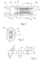
- Figs.2, 3 and 4 show details of the component 26 and its connection to inner and outer portions of the beam 17. As shown, this has an inner portion 17a and an outer portion 17b, the facing ends of which are fixed or clamped, for example by being held by bolts 27, to end plates 28 and 29 forming respectively the inner and outer ends of the component.
- end plates are connected by a torsion member 30 which is strongly fixed to the end plates so as to be capable of transmitting the torque forces experienced by the rotor back to the hub.
- the member 30 is of aluminum having a rectangular, and almost square, cross section.
- the amount of twisting experienced by the torque member 30 is controlled by two expandable control elements 32, which may be identical, and which extend from the end plate 29 and have outer ends close to the plate 28.
- Each comprises two parallel stacks of about 40 piezoelectric crystals or layers 33.
- the two adjacent stacks are each held in place by a central aluminum support plate 34 having an inner end flange 35 welded to the end plate 29 and having an outer end flange 36 which abuts the outer end of the stack of elements and holds these at all times in compression.
- Suitable piezoelectric elements are known as PZT crystals, and these are pre-compressed between the flanges 35 and 36 when they are inactive.
- the outer faces of flanges 36, and the cooperating inner face of plate 28, are provided with a material such as aluminum or brass which have suitably high friction.
- the crystals 33 are capable of expanding the stacks 32, overcoming the tension in support plate 34, to bring the surfaces of flanges 36 into engagement with the inner faces of plate 28.
- the stacks 32 are stiff enough in bending and shear, and the friction between the faces of flanges 36 and the plate 28 is sufficient, that this effect significantly alters the torsional stiffness of the component 26.
- the two control elements 32 have electrodes applied to opposite ends of the stacks of crystals 33, and are individually controlled so that the stiffness of the component can be controlled in stages.
- the control elements have their length varied according to a square wave control algorithm, at a rate suitable for dealing with vibrations in a helicopter rotor. A stiffness variation at about 4/rev or 5/rev may be suitable for this; the rate of variation for such rotors will usually be less than 100Hz. It is contemplated, however, that a similar system may be used for noise control, in which case stiffness variation at around 1000 Hz or more may be used. It is also possible to use more than two stiffness control elements, to give specially designed variations of stiffness with time to meet particular situations.
- control element 330.9 ⁇ Original structure elongation 0.9 ⁇ Final gap length 0 ⁇ (closed)
- Control element contact force 815 N Maximum shear stress at contact surface 2.64X10 6 N/m 2 Shear stress for slippage under the maximum external load 2.74X10 5 N/m 2 Maximum shear stiffness 18.17X10 4 N/m 2 Maximum shear stiffness/baseline shear stiffness 2.05
- Fig.5 shows the possible use of a similar variable torque component or "smart spring" 26 to replace a section of an aircraft wing spar, for reducing vibrations in the wing.
- Fig.6 indicates diagrammatically other locations where such a device may be used to reduce vibrations, for example in aircraft engine pylons and in tail components.
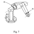
- Fig.7 indicates how the variable torque components may be incorporated into the arms of a robotic manipulator, to reduce its vibrations and to improve the precision with which such manipulators can operate.
Landscapes
- Engineering & Computer Science (AREA)
- Aviation & Aerospace Engineering (AREA)
- General Engineering & Computer Science (AREA)
- Mechanical Engineering (AREA)
- Physics & Mathematics (AREA)
- Acoustics & Sound (AREA)
- Vibration Prevention Devices (AREA)
Description
It is also possible to use more than two stiffness control elements, to give specially designed variations of stiffness with time to meet particular situations.
| PZT charge coefficient (d33): | 285 X 10-12 C/N |
| Length of PZT stack (I) | 20 cm |
| Number of layers in the PZT stack | 40 |
| | 10 |
| Maximum allowable PZT field | 1.0 X 10⁶ V/m |
| Maximum free strain in PZT stack | 285µ |
| Gap length (Δl) | 330µ=0.013'' |
| PZT Young's modulus | 67X109 N/m2 |
| Original structure, substructure Young's modulus (aluminum) | 71 X 109 N/m2 |
| Shear modulus (PZT, original structure & substructure) | 26.2X10⁹ N/m2 |
| Height (thickness) of composite structure (h) | 7 cm |
| Width of original structure (bo) | 7 cm |
| Width of PZT (bp) | 0.8 cm |
| Width of substructure (bs) | 0.1 cm |
| Maximum | 30 N.m |
| Static friction coefficient (clean surfaces) | 0.4 |
| Baseline shear stiffness | 8.86X10⁴ N/m2 |
| Elongation of | 330.9µ |
| Original structure elongation | 0.9µ |
| Final gap length | 0µ (closed) |
| Control element contact force | 815 N |
| Maximum shear stress at contact surface | 2.64X10⁶ N/m2 |
| Shear stress for slippage under the maximum external load | 2.74X10⁵ N/m2 |
| Maximum shear stiffness | 18.17X10⁴ N/m2 |
| Maximum shear stiffness/baseline shear stiffness | 2.05 |
Claims (10)
- A structural component having a stiffness which can be actively varied to control vibrations, characterised by having at least one recess or notch with opposed walls, which walls, in the absence of any intervening member, tend to move relative to each other when the component is stressed, and having a stiffness control element situated in the recess or notch, this element comprising electrically or magnetically expandable material capable of being rapidly expanded from a first condition in which the element is out of contact with one of the walls, to an expanded condition in which the element extends across the recess or notch and transmits forces from one of the walls to the other, thus altering the stiffness of the component.
- A structural component according to claim 1, wherein the element is expandable at a rate sufficiently high to allow the stiffness of the component to be varied at a rate consistent with a vibration of at least 100 Hz.
- A structural component according to claim 1, wherein the element is expandable at a rate sufficiently high to allow the stiffness of the component to be varied at a rate consistent with a vibration of at least 1000 Hz.
- A component according to claim 1, wherein said element contains piezoelectric material, and is connected to electrical means for controlling the stiffness of the component.
- A component according to claim 1, wherein said element contains electrostrictive material, and is connected to electrical means for controlling the stiffness of the component.
- A component according to claim 1, wherein said element contains magnetostrictive material, and is connected to magnetic means for controlling the stiffness of the component.
- A component according to claim 1, wherein a plurality of said stiffness controlling elements are situated in said recess, said elements being individually controlled and expandable to provide several degrees of stiffness for the component.
- A component according to claim 1, wherein said element has a first end fixed to a first wall of the recess, and has its second end engageable with the second wall of the recess, said second end and said second wall being provided with friction enhancing surfaces so that forces parallel to said walls can be transmitted between said second end and the second wall, whereby said element when expanded significantly increases the torsional stiffness of the component.
- A component according to claim 1, wherein said element has a first end fixed to a first wall of the recess, and has its second end engageable with the second wall of the recess, said second end and said second wall being provided with interengaging teeth so that forces parallel to said walls can be transmitted between said second end and the second wall, whereby said element when expanded significantly increases the torsional stiffness of the component.
- A helicopter rotor incorporating a component according to claim 1.
Applications Claiming Priority (3)
| Application Number | Priority Date | Filing Date | Title |
|---|---|---|---|
| US888600 | 1992-05-27 | ||
| US08/888,600 US5973440A (en) | 1997-07-07 | 1997-07-07 | Structural component having means for actively varying its stiffness to control vibrations |
| PCT/CA1998/000643 WO1999002398A1 (en) | 1997-07-07 | 1998-06-30 | Structural component having means for actively varying its stiffness to control vibrations |
Publications (2)
| Publication Number | Publication Date |
|---|---|
| EP0996570A1 EP0996570A1 (en) | 2000-05-03 |
| EP0996570B1 true EP0996570B1 (en) | 2002-05-08 |
Family
ID=25393505
Family Applications (1)
| Application Number | Title | Priority Date | Filing Date |
|---|---|---|---|
| EP98930609A Expired - Lifetime EP0996570B1 (en) | 1997-07-07 | 1998-06-30 | Structural component having means for actively varying its stiffness to control vibrations |
Country Status (5)
| Country | Link |
|---|---|
| US (1) | US5973440A (en) |
| EP (1) | EP0996570B1 (en) |
| CA (1) | CA2242214C (en) |
| DE (1) | DE69805302T2 (en) |
| WO (1) | WO1999002398A1 (en) |
Cited By (2)
| Publication number | Priority date | Publication date | Assignee | Title |
|---|---|---|---|---|
| US7453185B2 (en) | 2000-10-05 | 2008-11-18 | Eads Deutschland Gmbh | Piezoelectric extension actuator |
| DE102012208713A1 (en) | 2012-05-24 | 2013-11-28 | Technische Universität Bergakademie Freiberg | Carrier for use as active component for vibration compensation of adaptive supporting structures, has carrier elements with flanges and planks, where plank of one carrier element is engaged in plank of another carrier element |
Families Citing this family (20)
| Publication number | Priority date | Publication date | Assignee | Title |
|---|---|---|---|---|
| US6135713A (en) * | 1999-01-19 | 2000-10-24 | The Mcdonnell Douglas Helicopter Company | Helicopter rotor blade flap actuator government interest |
| US6544000B1 (en) * | 2001-07-26 | 2003-04-08 | The United States Of America As Represented By The Secretary Of The Navy | Magnetostrictive adjustment of propeller blade |
| US6699015B2 (en) * | 2002-02-19 | 2004-03-02 | The Boeing Company | Blades having coolant channels lined with a shape memory alloy and an associated fabrication method |
| US6796408B2 (en) | 2002-09-13 | 2004-09-28 | The Boeing Company | Method for vibration damping using superelastic alloys |
| US20040252005A1 (en) * | 2003-06-10 | 2004-12-16 | The Boeing Company | Shape memory alloy MEMS component deposited by chemical vapor deposition |
| US7598657B2 (en) * | 2005-01-18 | 2009-10-06 | Airbus Deutschland Gmbh | Structure element for an aircraft |
| US7360996B2 (en) * | 2005-12-07 | 2008-04-22 | General Electric Company | Wind blade assembly and method for damping load or strain |
| US8302456B2 (en) | 2006-02-23 | 2012-11-06 | Asylum Research Corporation | Active damping of high speed scanning probe microscope components |
| US7767944B2 (en) * | 2007-03-07 | 2010-08-03 | Raytheon Company | Piezoelectric fiber, active damped, composite electronic housings |
| US8210469B2 (en) * | 2008-06-27 | 2012-07-03 | Fred Nitzsche | Hybrid device for vibration control |
| US8573937B2 (en) * | 2008-11-21 | 2013-11-05 | Xzeres Corp. | System for providing dynamic pitch control in a wind turbine |
| US8718813B2 (en) * | 2009-09-21 | 2014-05-06 | GM Global Technology Operations LLC | Mechanical implement utilizing active material actuation |
| DE102010038408B4 (en) | 2010-07-26 | 2020-11-19 | Airbus Operations Gmbh | Structural element for an aircraft and spacecraft and method for producing such a structural element |
| DE102010039705B4 (en) | 2010-08-24 | 2020-02-27 | Airbus Operations Gmbh | Structural element for an aircraft and spacecraft and method for producing such a structural element |
| GB201117692D0 (en) * | 2011-10-13 | 2011-11-23 | Rolls Royce Plc | A distributed propulsion system and method of control |
| CN103093082B (en) * | 2012-12-25 | 2016-03-09 | 中国商用飞机有限责任公司 | Single beam of transonic flutter model of airplane and design method thereof |
| DE102013102812B4 (en) * | 2013-03-19 | 2017-01-26 | Airbus Operations Gmbh | Hull structure for a means of transport, means of transport and method of making a hull structure for a means of transport |
| KR102177156B1 (en) | 2014-03-10 | 2020-11-10 | 삼성전자주식회사 | robot and substrate processing apparatus including the same |
| US9383388B2 (en) | 2014-04-21 | 2016-07-05 | Oxford Instruments Asylum Research, Inc | Automated atomic force microscope and the operation thereof |
| CN105736620B (en) * | 2014-12-10 | 2017-09-29 | 中国飞机强度研究所 | A kind of piezo-electric type tuned mass damper |
Family Cites Families (13)
| Publication number | Priority date | Publication date | Assignee | Title |
|---|---|---|---|---|
| US2447333A (en) * | 1931-12-30 | 1948-08-17 | Us Navy | Ultra-audible sound reception |
| US2532876A (en) * | 1946-12-19 | 1950-12-05 | Asche Robert | Electromagnetic artificial muscle |
| EP0207095A4 (en) * | 1984-12-19 | 1989-03-13 | Gould Inc | A rare earth flextensional transducer. |
| US5082421A (en) | 1986-04-28 | 1992-01-21 | Rolls-Royce Plc | Active control of unsteady motion phenomena in turbomachinery |
| US5224826A (en) | 1989-07-26 | 1993-07-06 | Massachusetts Institute Of Technology | Piezoelectric helicopter blade flap actuator |
| US5440193A (en) * | 1990-02-27 | 1995-08-08 | University Of Maryland | Method and apparatus for structural, actuation and sensing in a desired direction |
| GB2348774B (en) * | 1990-11-28 | 2001-02-21 | Raytheon Co | Electro-acoustic transducers |
| FR2677415B1 (en) * | 1991-06-07 | 1995-04-07 | Thomson Csf | ACTIVE MECHANICAL VIBRATION COMPENSATION DEVICE. |
| US5210653A (en) * | 1992-06-08 | 1993-05-11 | Schell John D | External actuator for a deformable mirror |
| US5314308A (en) | 1992-12-11 | 1994-05-24 | Dynamic Engineering, Inc. | System for controlling higher harmonic vibrations in helicopter rotor blades |
| US5382134A (en) | 1993-11-01 | 1995-01-17 | General Electric Company | Active noise control using noise source having adaptive resonant frequency tuning through stiffness variation |
| US5660255A (en) * | 1994-04-04 | 1997-08-26 | Applied Power, Inc. | Stiff actuator active vibration isolation system |
| US5775715A (en) * | 1995-08-01 | 1998-07-07 | K-2 Corporation | Piezoelectric damper for a board such as a snow ski or snowboard |
-
1997
- 1997-07-07 US US08/888,600 patent/US5973440A/en not_active Expired - Lifetime
-
1998
- 1998-06-30 EP EP98930609A patent/EP0996570B1/en not_active Expired - Lifetime
- 1998-06-30 WO PCT/CA1998/000643 patent/WO1999002398A1/en not_active Ceased
- 1998-06-30 CA CA002242214A patent/CA2242214C/en not_active Expired - Fee Related
- 1998-06-30 DE DE69805302T patent/DE69805302T2/en not_active Expired - Lifetime
Cited By (2)
| Publication number | Priority date | Publication date | Assignee | Title |
|---|---|---|---|---|
| US7453185B2 (en) | 2000-10-05 | 2008-11-18 | Eads Deutschland Gmbh | Piezoelectric extension actuator |
| DE102012208713A1 (en) | 2012-05-24 | 2013-11-28 | Technische Universität Bergakademie Freiberg | Carrier for use as active component for vibration compensation of adaptive supporting structures, has carrier elements with flanges and planks, where plank of one carrier element is engaged in plank of another carrier element |
Also Published As
| Publication number | Publication date |
|---|---|
| DE69805302D1 (en) | 2002-06-13 |
| US5973440A (en) | 1999-10-26 |
| CA2242214C (en) | 2006-09-12 |
| CA2242214A1 (en) | 1999-01-07 |
| DE69805302T2 (en) | 2002-11-07 |
| EP0996570A1 (en) | 2000-05-03 |
| WO1999002398A1 (en) | 1999-01-21 |
Similar Documents
| Publication | Publication Date | Title |
|---|---|---|
| US5973440A (en) | Structural component having means for actively varying its stiffness to control vibrations | |
| Chen et al. | Induced strain actuation of composite beams and rotor blades with embedded piezoceramic elements | |
| Chen et al. | Hover testing of smart rotor with induced-strain actuation of blade twist | |
| US6299410B1 (en) | Method and apparatus for damping vibration in turbomachine components | |
| Heeg | Analytical and experimental investigation of flutter suppression by piezoelectric actuation | |
| Straub | A feasibility study of using smart materials for rotor control | |
| Hall et al. | Development of a piezoelectric servoflap for helicopter rotor control | |
| Park et al. | Bending and torsion models of beams with induced-strain actuators | |
| Yong et al. | Development of the smart spring for active vibration control of helicopter blades | |
| Bernhard et al. | Analysis of a bending-torsion coupled actuator for a smart rotor with active blade tips | |
| Samak et al. | Design of high force, high displacement actuators for helicopter rotors | |
| Walz et al. | Design and testing of a helicopter rotor model with smart trailing edge flaps | |
| Giurgiutiu | Recent advances in smart-material rotor control actuation | |
| Heeg | An analytical and experimental investigation of flutter suppression via piezoelectric actuation | |
| Wilkie et al. | Aeroelastic analysis of helicopter rotor blades incorporating anisotropic piezoelectric twist actuation | |
| Clement et al. | Bench-top characterization of an active rotor blade flap system incorporating c-block actuators | |
| Spencer et al. | Design and testing of a helicopter trailing edge flap with piezoelectric stack actuators | |
| Barrett et al. | Design and testing of a 1/12th-scale solid state adaptive rotor | |
| Wilbur et al. | Active-twist rotor control applications for UAVs | |
| Bernhard et al. | Development of a smart moving blade tip activated by a piezo-induced bending-torsion coupled beam | |
| Clement et al. | Wind tunnel testing of a high authority airspeed insensitive rotor blade flap | |
| Weisshaar | Aeroservoelastic control concepts with active materials | |
| Chattopadhyay et al. | Design of a smart flap using polymeric C-block actuators and a hybrid optimization technique | |
| Koratkar et al. | Analysis and testing of a mach-scaled helicopter rotor in hover with piezoelectric bender-actuated trailing-edge flaps | |
| Chen et al. | Induced strain actuation of composite beams and rotor blades with embedded piezoceramic elements |
Legal Events
| Date | Code | Title | Description |
|---|---|---|---|
| PUAI | Public reference made under article 153(3) epc to a published international application that has entered the european phase |
Free format text: ORIGINAL CODE: 0009012 |
|
| 17P | Request for examination filed |
Effective date: 20000124 |
|
| AK | Designated contracting states |
Kind code of ref document: A1 Designated state(s): DE FR GB IT |
|
| GRAG | Despatch of communication of intention to grant |
Free format text: ORIGINAL CODE: EPIDOS AGRA |
|
| 17Q | First examination report despatched |
Effective date: 20010730 |
|
| GRAG | Despatch of communication of intention to grant |
Free format text: ORIGINAL CODE: EPIDOS AGRA |
|
| GRAG | Despatch of communication of intention to grant |
Free format text: ORIGINAL CODE: EPIDOS AGRA |
|
| GRAH | Despatch of communication of intention to grant a patent |
Free format text: ORIGINAL CODE: EPIDOS IGRA |
|
| RIN1 | Information on inventor provided before grant (corrected) |
Inventor name: ZIMCIK, DAVID Inventor name: GREWAL, ANANT Inventor name: NITZSCHE, FRED |
|
| REG | Reference to a national code |
Ref country code: GB Ref legal event code: IF02 |
|
| GRAH | Despatch of communication of intention to grant a patent |
Free format text: ORIGINAL CODE: EPIDOS IGRA |
|
| GRAA | (expected) grant |
Free format text: ORIGINAL CODE: 0009210 |
|
| AK | Designated contracting states |
Kind code of ref document: B1 Designated state(s): DE FR GB IT |
|
| REF | Corresponds to: |
Ref document number: 69805302 Country of ref document: DE Date of ref document: 20020613 |
|
| ET | Fr: translation filed | ||
| PLBE | No opposition filed within time limit |
Free format text: ORIGINAL CODE: 0009261 |
|
| STAA | Information on the status of an ep patent application or granted ep patent |
Free format text: STATUS: NO OPPOSITION FILED WITHIN TIME LIMIT |
|
| 26N | No opposition filed |
Effective date: 20030211 |
|
| REG | Reference to a national code |
Ref country code: FR Ref legal event code: PLFP Year of fee payment: 18 |
|
| PGFP | Annual fee paid to national office [announced via postgrant information from national office to epo] |
Ref country code: GB Payment date: 20150624 Year of fee payment: 18 Ref country code: DE Payment date: 20150624 Year of fee payment: 18 |
|
| PGFP | Annual fee paid to national office [announced via postgrant information from national office to epo] |
Ref country code: FR Payment date: 20150608 Year of fee payment: 18 |
|
| PGFP | Annual fee paid to national office [announced via postgrant information from national office to epo] |
Ref country code: IT Payment date: 20150625 Year of fee payment: 18 |
|
| REG | Reference to a national code |
Ref country code: DE Ref legal event code: R119 Ref document number: 69805302 Country of ref document: DE |
|
| GBPC | Gb: european patent ceased through non-payment of renewal fee |
Effective date: 20160630 |
|
| REG | Reference to a national code |
Ref country code: FR Ref legal event code: ST Effective date: 20170228 |
|
| PG25 | Lapsed in a contracting state [announced via postgrant information from national office to epo] |
Ref country code: DE Free format text: LAPSE BECAUSE OF NON-PAYMENT OF DUE FEES Effective date: 20170103 Ref country code: FR Free format text: LAPSE BECAUSE OF NON-PAYMENT OF DUE FEES Effective date: 20160630 |
|
| PG25 | Lapsed in a contracting state [announced via postgrant information from national office to epo] |
Ref country code: GB Free format text: LAPSE BECAUSE OF NON-PAYMENT OF DUE FEES Effective date: 20160630 |
|
| PG25 | Lapsed in a contracting state [announced via postgrant information from national office to epo] |
Ref country code: IT Free format text: LAPSE BECAUSE OF NON-PAYMENT OF DUE FEES Effective date: 20160630 |