EP0996363B1 - Endovaginal sonography guidance of intra-uterine procedures - Google Patents
Endovaginal sonography guidance of intra-uterine procedures Download PDFInfo
- Publication number
- EP0996363B1 EP0996363B1 EP98933199A EP98933199A EP0996363B1 EP 0996363 B1 EP0996363 B1 EP 0996363B1 EP 98933199 A EP98933199 A EP 98933199A EP 98933199 A EP98933199 A EP 98933199A EP 0996363 B1 EP0996363 B1 EP 0996363B1
- Authority
- EP
- European Patent Office
- Prior art keywords
- ultrasound transducer
- medical instrument
- endovaginal
- connector
- respect
- Prior art date
- Legal status (The legal status is an assumption and is not a legal conclusion. Google has not performed a legal analysis and makes no representation as to the accuracy of the status listed.)
- Expired - Lifetime
Links
- 238000000034 method Methods 0.000 title claims abstract description 38
- 238000002604 ultrasonography Methods 0.000 claims abstract description 98
- 238000012544 monitoring process Methods 0.000 claims abstract description 27
- 210000003679 cervix uteri Anatomy 0.000 claims abstract description 20
- 238000003780 insertion Methods 0.000 claims abstract description 10
- 230000037431 insertion Effects 0.000 claims abstract description 10
- 210000001215 vagina Anatomy 0.000 claims abstract description 9
- 230000005672 electromagnetic field Effects 0.000 claims description 14
- 238000003384 imaging method Methods 0.000 claims description 14
- 230000000007 visual effect Effects 0.000 claims description 4
- 238000001356 surgical procedure Methods 0.000 description 15
- 210000001161 mammalian embryo Anatomy 0.000 description 14
- 238000005070 sampling Methods 0.000 description 13
- 238000012546 transfer Methods 0.000 description 12
- 210000003101 oviduct Anatomy 0.000 description 11
- 230000001225 therapeutic effect Effects 0.000 description 9
- 210000001519 tissue Anatomy 0.000 description 8
- 238000001839 endoscopy Methods 0.000 description 7
- 239000000523 sample Substances 0.000 description 6
- 230000000295 complement effect Effects 0.000 description 5
- 230000002357 endometrial effect Effects 0.000 description 5
- 206010061692 Benign muscle neoplasm Diseases 0.000 description 4
- 201000004458 Myoma Diseases 0.000 description 4
- 239000003433 contraceptive agent Substances 0.000 description 4
- 230000002254 contraceptive effect Effects 0.000 description 4
- 208000016018 endometrial polyp Diseases 0.000 description 4
- 210000004696 endometrium Anatomy 0.000 description 4
- 238000000605 extraction Methods 0.000 description 4
- 230000001605 fetal effect Effects 0.000 description 4
- 210000003754 fetus Anatomy 0.000 description 4
- 230000009027 insemination Effects 0.000 description 4
- 230000009897 systematic effect Effects 0.000 description 4
- 206010046811 uterine polyp Diseases 0.000 description 4
- 206010046810 Uterine perforation Diseases 0.000 description 3
- 210000004252 chorionic villi Anatomy 0.000 description 3
- 239000000835 fiber Substances 0.000 description 3
- 210000004291 uterus Anatomy 0.000 description 3
- 102000002322 Egg Proteins Human genes 0.000 description 2
- 108010000912 Egg Proteins Proteins 0.000 description 2
- 238000002669 amniocentesis Methods 0.000 description 2
- 238000001574 biopsy Methods 0.000 description 2
- 238000009802 hysterectomy Methods 0.000 description 2
- 210000004379 membrane Anatomy 0.000 description 2
- 239000012528 membrane Substances 0.000 description 2
- 238000002324 minimally invasive surgery Methods 0.000 description 2
- 238000012986 modification Methods 0.000 description 2
- 230000004048 modification Effects 0.000 description 2
- 210000004681 ovum Anatomy 0.000 description 2
- 229910001220 stainless steel Inorganic materials 0.000 description 2
- 239000010935 stainless steel Substances 0.000 description 2
- 239000000126 substance Substances 0.000 description 2
- 210000001835 viscera Anatomy 0.000 description 2
- 206010002091 Anaesthesia Diseases 0.000 description 1
- 206010028980 Neoplasm Diseases 0.000 description 1
- 239000000020 Nitrocellulose Substances 0.000 description 1
- 208000031481 Pathologic Constriction Diseases 0.000 description 1
- 206010039491 Sarcoma Diseases 0.000 description 1
- 210000000683 abdominal cavity Anatomy 0.000 description 1
- 230000003187 abdominal effect Effects 0.000 description 1
- 238000009557 abdominal ultrasonography Methods 0.000 description 1
- 206010000269 abscess Diseases 0.000 description 1
- XAGFODPZIPBFFR-UHFFFAOYSA-N aluminium Chemical compound [Al] XAGFODPZIPBFFR-UHFFFAOYSA-N 0.000 description 1
- 229910052782 aluminium Inorganic materials 0.000 description 1
- 239000004411 aluminium Substances 0.000 description 1
- 238000001949 anaesthesia Methods 0.000 description 1
- 230000037005 anaesthesia Effects 0.000 description 1
- 230000000740 bleeding effect Effects 0.000 description 1
- 201000011510 cancer Diseases 0.000 description 1
- 230000001427 coherent effect Effects 0.000 description 1
- 238000010276 construction Methods 0.000 description 1
- 230000006378 damage Effects 0.000 description 1
- 230000003247 decreasing effect Effects 0.000 description 1
- 238000003745 diagnosis Methods 0.000 description 1
- 208000037265 diseases, disorders, signs and symptoms Diseases 0.000 description 1
- 208000035475 disorder Diseases 0.000 description 1
- 210000002257 embryonic structure Anatomy 0.000 description 1
- 239000012530 fluid Substances 0.000 description 1
- 238000002695 general anesthesia Methods 0.000 description 1
- 208000014674 injury Diseases 0.000 description 1
- 238000002357 laparoscopic surgery Methods 0.000 description 1
- 238000002350 laparotomy Methods 0.000 description 1
- 230000036210 malignancy Effects 0.000 description 1
- 239000000463 material Substances 0.000 description 1
- 210000000713 mesentery Anatomy 0.000 description 1
- 229920001220 nitrocellulos Polymers 0.000 description 1
- 210000002747 omentum Anatomy 0.000 description 1
- 230000003169 placental effect Effects 0.000 description 1
- 210000005059 placental tissue Anatomy 0.000 description 1
- 230000036262 stenosis Effects 0.000 description 1
- 208000037804 stenosis Diseases 0.000 description 1
- 230000008733 trauma Effects 0.000 description 1
- 210000000626 ureter Anatomy 0.000 description 1
- 210000003932 urinary bladder Anatomy 0.000 description 1
Images

Classifications
-
- A—HUMAN NECESSITIES
- A61—MEDICAL OR VETERINARY SCIENCE; HYGIENE
- A61B—DIAGNOSIS; SURGERY; IDENTIFICATION
- A61B8/00—Diagnosis using ultrasonic, sonic or infrasonic waves
- A61B8/42—Details of probe positioning or probe attachment to the patient
- A61B8/4209—Details of probe positioning or probe attachment to the patient by using holders, e.g. positioning frames
-
- A—HUMAN NECESSITIES
- A61—MEDICAL OR VETERINARY SCIENCE; HYGIENE
- A61B—DIAGNOSIS; SURGERY; IDENTIFICATION
- A61B17/00—Surgical instruments, devices or methods
- A61B17/42—Gynaecological or obstetrical instruments or methods
- A61B17/4241—Instruments for manoeuvring or retracting the uterus, e.g. during laparoscopic surgery
-
- A—HUMAN NECESSITIES
- A61—MEDICAL OR VETERINARY SCIENCE; HYGIENE
- A61B—DIAGNOSIS; SURGERY; IDENTIFICATION
- A61B90/00—Instruments, implements or accessories specially adapted for surgery or diagnosis and not covered by any of the groups A61B1/00 - A61B50/00, e.g. for luxation treatment or for protecting wound edges
- A61B90/50—Supports for surgical instruments, e.g. articulated arms
-
- A—HUMAN NECESSITIES
- A61—MEDICAL OR VETERINARY SCIENCE; HYGIENE
- A61B—DIAGNOSIS; SURGERY; IDENTIFICATION
- A61B17/00—Surgical instruments, devices or methods
- A61B17/00234—Surgical instruments, devices or methods for minimally invasive surgery
- A61B2017/00292—Surgical instruments, devices or methods for minimally invasive surgery mounted on or guided by flexible, e.g. catheter-like, means
- A61B2017/00296—Surgical instruments, devices or methods for minimally invasive surgery mounted on or guided by flexible, e.g. catheter-like, means mounted on an endoscope
-
- A—HUMAN NECESSITIES
- A61—MEDICAL OR VETERINARY SCIENCE; HYGIENE
- A61B—DIAGNOSIS; SURGERY; IDENTIFICATION
- A61B17/00—Surgical instruments, devices or methods
- A61B17/42—Gynaecological or obstetrical instruments or methods
- A61B2017/4216—Operations on uterus, e.g. endometrium
Definitions
- the present invention relates to apparatus system for real-time endovaginal sonography guidance of intra-uterine, cervical and tubal procedures.
- Endovaginal ultrasound transducers for diagnosis and monitoring of obstetric and gynaecologic disorders are well known in the art, for example from US 5,199,437.
- the use of such endovaginal probes for real-time monitoring of surgical procedures is very limited.
- ultrasound transducers including a needle and/or catheter guide attached thereto for introducing a needle and/or catheter to a targeted tissue.
- surgical procedures which may be carried out by such endovaginal probes are usually very limited and include puncturing and drainage of abscesses, local tissue sampling and fluid collection.
- United States Patent No. 5,037,430 to Hasson discloses a clamping device for positioning and holding gynaecological instruments.
- a second clamp is located intermediate the ends of the clamping device for releasably clamping onto the gynaecological instrument to hold the instrument in proper position relative to the uterus.
- United States Patent Number 4,838,506 to Cooper discloses a holder for a needle guide sleeve for use in cooperation with an ultrasonic probe.
- the holder has an arm with a slot through which the needle guide sleeve rests and is movable in two directions.
- the prior art fails to provide endovaginal apparatus for real-time monitoring and guidance of more complicated surgical procedures.
- the prior art fails to provide endovaginal apparatus for real-time monitoring and guidance of intra-uterine, cervical and tubal procedures requiring manual dexterity of a surgeon, such as, but not limited to, (i) curettage or evacuation of the uterine cavity for diagnostic and/or therapeutic purposes; (ii) removal of an endometrial polyp, submucous myoma or other tissue; (iii) introduction or extraction of an intra-uterine contraceptive device (IUCD) and other foreign bodies; (iv) systematic sampling of the endometrium and/or the endocervix for diagnostic purposes; (v) embryo transfer into the endometrial cavity; (vi) embryo transfer into the fallopian tube; (vii) fallopian tube canullation; (viii) ultrasound guided fetal reduction; (ix) simultaneous insertion of an image transmitting device such as endoscopy equipment into the uterine cavity for complementary diagnostic and/or
- Transabdominal ultrasound is regularly not used for real-time monitoring and guidance of such surgical procedures due to its relatively limited resolution, the need to keep the patient's urinary bladder full during operation, and the need of extra-operating stuff.
- the main dangers of such uterine perforation include bleeding and trauma to the abdominal viscera as well as damage to internal organs such as bowel, omentum, mesentery, ureter and fallopian tube.
- exploration of the abdominal cavity by laparoscopy or laparotomy is often needed due to accidental uterine perforation.
- Other poor outcomes of blind operation include, for example, failure to completely remove uterine tissues such as placental or fetal tissues, which necessitates a second curettage under general anesthesia, or misplacement of foreign bodies or embryos therein.
- an apparatus for guidance and monitoring of intra-uterine, cervical and tubal procedures comprising an assembly including: (a) an endovaginal ultrasound transducer being adapted for insertion into a portion of a patient's vagina; characterised in that the assembly further includes:(b) a cervical holder, including: (i) two arms having a securing member; and (ii) two holders, said holders being for holding the patient's cervix; and (c) a connector for interconnecting said ultrasound transducer and said cervical holder.
- a system for guidance and monitoring of intra-uterine, cervical and tubal procedures comprising (a) an assembly being operable by a weak hand of a surgeon, the assembly being provided by an apparatus according to the first aspect of the present invention; (b) a medical instrument for performing the procedure, the medical instrument being operable by a strong hand of the surgeon; and (c) a device for monitoring an alignment of the medical instrument with respect to the endovaginal ultrasound transducer and therefore also with respect to the ultrasound beam.
- the present invention successfully addresses the shortcomings of the presently known configurations by providing an apparatus and system for real-time endovaginal sonography guidance and monitoring of intra-uterine, cervical and tubal procedures, such as, but not limited to, (i) curettage or evacuation of the uterine cavity for diagnostic and/or therapeutic purposes; (ii) removal of an endometrial polyp, submucous myoma or other tissue; (iii) introduction or extraction of an intra-uterine contraceptive device (IUCD) and other foreign bodies; (iv) systematic sampling of the endometrium and/or the endocervix for diagnostic purposes; (v) embryo transfer into the endometrial cavity; (vi) embryo transfer into the fallopian tube; (vii) fallopian tube canullation; (viii) ultrasound guided fetal reduction; (ix) simultaneous insertion of an image transmitting device such as endoscopy equipment into the uterine cavity for complementary diagnostic and/or therapeutic purposes; (x) chorionic villi sampling; (xi) fe
- the present invention discloses novel apparatus and system for real-time endovaginal sonography guidance and monitoring of intra-uterine, cervical and tubal procedures.
- the cervical holder and the endovaginal ultrasound transducer are preferably held by the weak of the surgeon so that the other strong hand of the surgeon is free to conduct the surgical procedure. Since in most cases the diameter of the endovaginal ultrasound transducer is substantially small, the surgeon may conveniently introduce a medical instrument such as a curette through the cervix into the uterine cavity of the patient.
- the surgical procedure is continuously guided and monitored by means of the endovaginal ultrasound transducer.
- the medical instrument (or tool) is aligned with respect to the ultrasonic beam of the transducer, such that the surgeon can, view the treated region before, during and after the procedure, and conveniently and safely direct the medical instrument of choice to that region.
- the present invention is of apparatus and system for real-time endovaginal sonography guidance of intra-uterine, cervical and tubal surgical and non-surgical procedures.
- the present invention can be used to guide and monitor intra uterine, cervical and tubal procedures such as, but not limited to, (i) curettage or evacuation of the uterine cavity for diagnostic and/or therapeutic purposes; (ii) removal of an endometrial polyp, submucous myoma or other tissue; (iii) introduction or extraction of an intra-uterine contraceptive device (IUCD) and other foreign bodies; (iv) systematic sampling of the endometrium and/or the endocervix for diagnostic purposes; (v) embryo transfer into the endometrial cavity; (vi) embryo transfer into the fallopian tube; (vii) fallopian tube canullation; (viii) ultrasound guided fetal reduction; and (ix) simultaneous insertion of an image transmitting device such as endoscopy equipment into the uterine cavity for complementary diagnostic and/or therapeutic purposes.
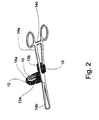
- FIG. 1 illustrates a preferred embodiment of an apparatus according to the present invention, which is referred to herein below as apparatus 9 .
- apparatus 9 includes an endovaginal ultrasound transducer 10 , a cervical holder 14 and a connector 12 for connecting endovaginal ultrasound transducer 10 to cervical holder 14 .
- endovaginal transducer 10 features substantially small diameter so as to allow simultaneous insertion of transducer 10 and cervical holder 14 into the patient's vagina.
- Cervical holder 14 is preferably a conventional cervical holder, including two arms 14a each including a securing member 14c; and two holders 14b for holding a cervix of a patient, as for example shown in Figure 3.
- connector 12 preferably includes a first segment 12a and a second segment 12b .
- first segment 12a features a flat configuration and includes a circular aperture 16 for accommodating transducer 10 therein.
- an adjustment annular member 16a is embedded within aperture 16 for adjusting the orientation of transducer 10 relative to first segment 12a .
- second segment 12b features an elongated configuration and includes a protrusion 18 for locking connector 12 between arms 14a, as holders 14b grip the cervix of the patient upon securing of cervical holder 14 by means of securing member 14c .
- the dimensions of connector 12 may be specifically adapted for various probes.
- Connector 12 may be made of any appropriate material.
- connector 12 is disposable.
- connector 12 and cervical holder 14 are integrally made.
- connector 12 and endovaginal ultrasound transducer 10 are integrally made.
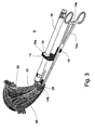
- FIG. 3 illustrates the use of apparatus 9 according to the present invention for monitoring and guiding curettage of a patient's uterus 40.
- apparatus 9 which is also shown in Figure 1
- endovaginal ultrasound transducer 10 is assembled with connector 12 by inserting transducer 10 into aperture 16 of connector 12 .
- Cervical holder 14 is then used to grip the cervix 28 of a patient by means of holders 14b , such that protrusion 18 of connector 12 is locked between arms 14a when securing the cervical holder.
- endovaginal transducer 10 is then slidably inserted into the fornix of the patient, and its desired orientation is set so as to allow optimal guidance and monitoring of the intra-uterine procedure.
- cervical holder 14 and endovaginal ultrasound transducer 10 are preferably held by one hand of the surgeon so that the other hand is free to conduct the surgical procedure. Since the diameter of endovaginal ultrasound transducer 10 is substantially small, the operator may conveniently introduce a medical instrument such as curette 32 through the cervix 28 into the uterine cavity 30 of the patient. The surgical procedure is then carried out and is continuously guided and monitored by means of endovaginal ultrasound transducer 10. The orientation of transducer 10 relative to connector 12 may be continuously changed as the surgical procedure proceeds.
- guiding a curettage is used herein as a non limiting example for guiding any other medical instrument (tool) for diagnostic and/or surgical purposes into the cervix, uterine or fallopian tubes of the patient.
- Such instruments include, but are not limited to, uterine sound - plastic disposable or stainless steel, uterine dilators - hegar double or single end, uterine curettes, uterine dressing, hysterectomy forceps, ovum forceps, intra-uterine device remover, biopsy punches, endocervical speculum, aspirate curette, vacuum curette, aspirate tube, coagulator, embryo transfer set, insemination device, embryo gamete intra-fallopian transfer (GIFT) catheter, embryo intra uterine insemination (IUI) catheter, KarmanTM catheter for uterine aspiration, minimally invasive surgery equipment, such as, grasping forceps, scissors, light dissecting/grasping forceps, diathermy balloon intra cavitary, IUCD, hysterosalpingography catheter, uterine catheter, tubal catheter, brush vacuum intrauterine sound, uterine elevator, SpackmannTM cannula, ScottTM uterine manipulator,
- a common feature to the above listed medical instruments is that they are typically operated by the strong hand (e.g., the right hand of a right handed surgeon) of the surgeon, while apparatus 9 is held and operated by the weak hand (e.g., the left hand of a right handed surgeon) thereof.
- the strong hand e.g., the right hand of a right handed surgeon
- the weak hand e.g., the left hand of a right handed surgeon
- connector 12 is used to connect endovaginal ultrasound transducer 10 to an image transmitting device for diagnostic and/or therapeutic purposes such that ultrasound transducer 10 is preferably inserted into the patient's fornix and the image transmitting device is preferably inserted through the cervical canal into the uterine cavity.
- the image transmitting device may be, for example, an optic fiber, or endoscopy equipment.
- the image transmitting device may include an image transmitting element such as a CCD or a video camera.
- transducer 10 may be connected by means of connector 12 to an endoscopy equipment so as to allow simultaneous monitoring of the surgical procedure by means of two complementary methods, thereby enabling to accurately determine the position of a medical instrument with relation to the uterine wall.
- Apparatus 9 described hereinabove not only allows for ultrasonic view of the treated area in the cervix, uterine or fallopian tube, it further allows for ultrasonic view of the operating medical instrument. This is the case, provided that the medical instrument is brought "inside” or “into” the beam generated by the ultrasound transducer, which beam is shaped as a triangle located within the ultrasound plane of view.
- apparatus 9 is inserted into a portion of the vagina of the patient prior to the insertion of a medical instrument through the cervix, and further since the medical instrument and apparatus 9 are each held by a different hand of the surgeon, a non-practiced surgeon may find it difficult to bring the medical instrument "inside" or "into” the sonography beam.
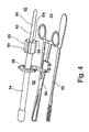
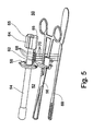
- system 50 a system for guidance and monitoring of intra-uterine, cervical and tubal procedures, which is referred to hereinbelow as system 50.
- System 50 includes an assembly 52 typically operable by a weak hand of a surgeon.
- Assembly 52 includes an endovaginal ultrasound transducer 54 adapted for insertion into a portion of a patient's vagina.
- Endovaginal ultrasound transducer 54 serves for generating an ultrasound beam.
- Assembly 50 further includes a cervical holder 56 for holding a patient's cervix.
- a connector 58 is used for interconnecting ultrasound transducer 54 and cervical holder 56 .
- Assembly 52 as so far described, is, in fact, structurally and functionally identical to apparatus 9 ( Figure 1) described hereinabove and serves identical proposes. Thus, all the features described hereinabove with respect to apparatus 9 apply also to assembly 52 .
- System 50 further includes a medical instrument 60 .
- Instrument 60 serves to perform the intra-uterine, cervical or tubal procedure and is typically operable by a strong hand of the surgeon.
- Medical instrument 60 may be a diagnostic instrument, such as, but not limited to, hysterosalpingography catheter, uterine catheter, tubal catheter, brush cytology, cervical adapter for hydrotubation, uterine controlling instruments, vacuum intrauterine sound, uterine elevator, SpackmannTM cannula, ScottTM uterine manipulator, HulkaTM controlling tenaculum or forceps, rocket vacuum aspirator curette, uterine depth probe, sampling devices, NOVAKTM, KEVORKIANTM, EXPORATM and PipelleTM, or a surgical instrument, such as, but not limited to, uterine sound plastic disposable or stainless steel, uterine dilators - hegar double or single end, uterine curettes, uterine dressing, hysterectomy forceps, ovum forceps, intra-
- a common feature to the above listed medical instruments is that they are all typically operated by the strong hand (e.g., the right hand of a right handed surgeon) of the surgeon, while assembly 52 is held and operated by the weak hand (e.g., the left hand of a right handed surgeon) thereof.
- the strong hand e.g., the right hand of a right handed surgeon
- the weak hand e.g., the left hand of a right handed surgeon
- System 50 further includes a device 62 which serves for monitoring the alignment of medical instrument 60 with respect to endovaginal ultrasound transducer 54 and therefore also with respect to the ultrasound beam generated thereby.
- Device 62 is typically connected to the distal end of transducer 54 via a suitable connector, generally marked as 64 . However, direct connection, and other locations are also envisaged.
- Connector 64 is preferably equipped with wings 65 , being aligned within the plane of the ultrasound beam.
- distal end 68 of transducer 54 is asymmetrically formed, such that when connector 64 is applied thereon, wings 65 acquire their respective positions.
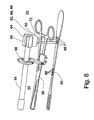
- device 62 includes an extension 66 coaxially connected at a distal end 69 of endovaginal ultrasound transducer 54 , thereby facilitating visual alignment of medical instrument 60 with respect to endovaginal ultrasound transducer 54 and therefore also with respect to the ultrasound beam generated thereby.
- the surgeon while inserting medical instrument 60 through the cervix of the patient, the surgeon ensures that instrument 60 parallels extension 66 , to thereby direct instrument 60 "inside” or "into” the ultrasound beam.
- device 62 includes at least one light beam generator 68 (say, e.g., two, four are shown) connected to assembly 52 , preferably to transducer 54 thereof, preferably via connector 64.
- Light beam generators 68 serve for generating at least one focused light beam 70 .
- Light beams 70 reside substantially in the plane defined by the ultrasound beam of transducer 54 .
- light beams 70 serve for facilitating visual alignment of medical instrument with respect to endovaginal ultrasound transducer 54 and therefore also with respect to the ultrasound beam.
- Each of light beam generators 68 may be, for example, a laser source, generating, for example, a green laser beam, which is known not to be absorbed by living tissues. However, non-coherent light sources are also applicable.
- Light beam generators 68 preferably receive energy from a power source, e.g., a battery, implemented in a battery housing located within connector 64 .
- Each of generators 68 may be, for example, a pointer type laser diode, having, for example, a maximum output below 5 mW, wavelength of 650 nm, with beam dimensions of about 3.0 nm x 2.5 nm.
- a suitable diode is the "ES smallest laser pointer" Cat. No. D53,050 which is available from Edmund Scientific, Industrial Optics Division, Barrington, NJ 08007-1380 U.S.A.
- Generators 68 may alternatively be selected to generate a stripe of light. Edmund Scientific Cat. No. D52,562 "Gamma-x laser light show".
- Each of generators 68 preferably further includes a beam splitter, e.g., a TECH SPECTM pellicle beam splitter.
- the pellicles are very thin nitrocellulose membranes bonded to lapped aluminium frames. Ghost images are eliminated by the thinness of the membrane as the second surface reflection superimposed on the first surface reflection.
- the uncoated pellicle reflects 8 % and transmits 92 % through the visible and near infrared regions.
- the pellicles' thickness is in the range of 2 ⁇ m, their index of reflection is (Nd):1.5. Suitable pellicles are available from Edmund Scientific, Industrial Optics Division, Barrington, NJ 08007-1380 U.S.A., Cat. No. D39,478):
- device 62 includes an imaging implement 72 connected to assembly 52 , preferably to transducer 54 thereof, preferably via connector 64 .
- Imaging implement 72 serves for generating an image of objects in the plane defined by the ultrasound beam.
- Implement 72 thereby serves for facilitating alignment of medical instrument 60 with respect to endovaginal ultrasound transducer 54 and therefore also with respect to the ultrasound beam generated thereby.
- the surgeon while inserting medical instrument 60 through the cervix of the patient, the surgeon ensures that imaging implement 72 "sees” or “captures” instrument 60 , to thereby direct instrument 60 "inside” or "into” the ultrasound beam.
- the image generated by implement 72 is preferably displayed on a screen. A single screen may serve for presenting, in real time, the ultrasound image perceived through transducer 54 and the image perceived through imaging implement 72 .
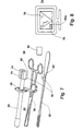
- FIG 8 An example is shown in Figure 8, showing a screen 74 displaying an ultrasound image 76 and an image 78 , perceived through implement 72 .
- Implement 72 is positioned such that when image 78 shows instrument 60 in, for example, a vertical alignment with respect to screen 74 , as indicated in Figure 8 by 60a , then the surgeon knows that medical instrument 60 is aligned with respect to endovaginal ultrasound transducer 54 and therefore also with respect to the ultrasound beam generated thereby.
- screen 74 may further provide a displayed grid or coordinates, such that assessing the verticality of the image 60a of instrument 60 is facilitated.
- Implement 72 preferably receive energy from a power source, e.g., a battery, implemented in a battery housing located within connector 64.
- a power source e.g., a battery
- imaging implement 72 is a camera 82 , e.g., a charge coupled device (CCD) camera equipped with a lens or optic fibers arrangement, which is adapted to perceive light in the visible range.
- a camera sensitive to light in the infrared range i.e., an infrared (thermal) camera 84 , which may similarly include a lens or an optic fibers arrangement.
- imaging implement 72 is an ultrasound implement 86 .
- imaging implement 72 is an X ray implement. In the latter case, an X rays sensitive plate is provided to perceive the image of instrument 60 thereby. Such plates are well known in the art. In the latter case, an X rays
- an image of instrument 60 is generated, which image enables the surgeon to direct instrument 60 "inside” or “into” the beam generated by ultrasound transducer 54 .
- medical instrument 60 is provided with marks 88 along at least a portion thereof. Marks 88 are selected identifiable by imaging implement 72 of choice and are therefore usable for image recognition analysis, which may be used to estimate the depth to which instrument 60 has been inserted at any given time. Image recognition is well known art and therefore will not be further elaborated herein.
- marks 88 must depend on the nature of imaging implement 72 of choice. Thus, if a CCD camera is selected, marks 88 may acquire a color distinguishable from the background color of instrument 60. If an infrared (thermal) camera is selected, marks 88 may be applied, for example, as substances of increased or decreased heat conductivity as compared with the substance from which instrument 60 is made. If ultrasound or X ray implements are selected, marks 88 may be applied, for example, as holes, recessions, protrusions, etc., to render them distinguishable from the background of instrument 60 . In each of these cases, marks 88 may be further selected distinguishable from one another in a fashion, e.g., similar to a bar-code, such that image recognition analysis may be applied.
- a suitable CCD is a CCD sensitive to light at 0.2 lux, having a S/N ratio greater than 46 Db.
- the CCD is preferably monochromatic and is capable of sensing an area of 6.4 X 4.8 mm.
- the CCD preferably features miniature size e.g., 30 x 30 x 60 mm, and low weight, e.g., 120 grams.
- a CCD obeying all of the above criteria is distributed by Edmund Scientific, Cat No. D39,244.
- device 62 includes at least two electromagnetic field generators 90 which serve for generating electromagnetic fields.
- One of electromagnetic field generators 90 is connected to assembly 52 , preferably to transducer 54 thereof, preferably via connector 64 .
- the other electromagnetic field generator 90 is connected to medical instrument 60.
- device 62 further includes at least one electromagnetic field sensor, generally indicated by 92 .
- Sensor 92 is positioned in a predetermined position in space, such that by analyzing the magnetic fields perceived by electromagnetic sensor 92 , spatial information of the relative locations of electromagnetic field generators 90 and therefore of transducer 54 and medical instrument 60 is obtainable, thereby facilitating alignment of medical instrument 60 with respect to endovaginal ultrasound transducer 54 and therefore also with respect to the ultrasound beam generated thereby. Further description concerning the operation of electromagnetic field generators and electromagnetic field sensors and the use of the latter to retrieve spatial information of the formers is disclosed in, for example, PCT/IL96/00050 (WO 97/03609) and further in U.S. Pat No. 4,945,305.
- Generators 90 are preferably powered by a mutual power source implemented in a dedicated housing in connector 64 or by independent power sources. Suitable power wiring is envisaged.
- a method of guidance and monitoring of intra-uterine, cervical and tubal procedures is effected by executing the following method steps, in which is a first step a cervical holder is employed for holding a patient's cervix. In a second step an endovaginal ultrasound transducer is inserted into a portion of the patient's vagina. The endovaginal ultrasound transducer serves for generating an ultrasound beam. The ultrasound transducer and the cervical holder are inter-connected there between by a connector to form an assembly which further includes a device for monitoring an alignment of a medical instrument with respect to the endovaginal ultrasound transducer and therefore also with respect to the ultrasound beam generated thereby.
- a third step of the method the procedure is performed by (i) pointing the endovaginal ultrasound transducer such that a treated area is identifiable; and (ii) inserting the medical instrument through the cervix, while holding the patient's cervix by the cervical holder and via the device, aligning the medical instrument with respect to endovaginal ultrasound transducer and therefore also with respect to the ultrasound beam.
- a fourth step the procedure and medical instrument are both monitored in real-time by the ultrasound transducer.
Landscapes
- Health & Medical Sciences (AREA)
- Life Sciences & Earth Sciences (AREA)
- Surgery (AREA)
- Public Health (AREA)
- Nuclear Medicine, Radiotherapy & Molecular Imaging (AREA)
- General Health & Medical Sciences (AREA)
- Engineering & Computer Science (AREA)
- Biomedical Technology (AREA)
- Heart & Thoracic Surgery (AREA)
- Medical Informatics (AREA)
- Molecular Biology (AREA)
- Veterinary Medicine (AREA)
- Animal Behavior & Ethology (AREA)
- Pathology (AREA)
- Radiology & Medical Imaging (AREA)
- Physics & Mathematics (AREA)
- Biophysics (AREA)
- Oral & Maxillofacial Surgery (AREA)
- Gynecology & Obstetrics (AREA)
- Pregnancy & Childbirth (AREA)
- Reproductive Health (AREA)
- Ultra Sonic Daignosis Equipment (AREA)
- Measuring And Recording Apparatus For Diagnosis (AREA)
- Surgical Instruments (AREA)
- Medicines Containing Plant Substances (AREA)
Abstract
Description
Claims (19)
- An apparatus for guidance and monitoring of intra-uterine, cervical and tubal procedures, comprising an assembly (9;52) including:(a) an endovaginal ultrasound transducer (10; 54) being adapted for insertion into a portion of a patient's vagina;
characterised in that the assembly (9;52) further includes:(b) a cervical holder (14; 56), for holding the patient's cervix; and(c) a connector (12; 58) for interconnecting said ultrasound transducer (16; 54) and said cervical holder (14; 56). - The apparatus of claim 1, wherein said cervical holder (14; 56) includes two arms (14a) having a securing member (14c) and two holders (14b), said holders (14b) being for holding the patient's cervix.
- The apparatus of claim 1 or 2, wherein said connector (12) includes an aperture (16) for accommodating said ultrasound transducer (10) therein.
- The apparatus of claim 1, 2 or 3, wherein said connector (12) includes an adjustment member (16a) for adjusting the orientation of said ultrasound transducer (10) relative to said connector (12).
- The apparatus of claim 2, 3 or 4, wherein said connector (12) includes a protrusion (18) for locking said connector (12) between said arms (14a) of said cervical holder (14) upon securing of said cervical holder (14) by means of said securing member (14c).
- The apparatus of any preceding claim, wherein said connector (12) and said cervical holder (14) are integrally made.
- The apparatus of any one of claims 1 to 5, wherein said connector (12) and said ultrasound transducer (10) are integrally made.
- A system (50) for guidance and monitoring of intra-uterine, cervical and tubal procedures, the system comprising:(a) an assembly (52) being operable by a weak hand of a surgeon, said assembly (52) being provided by an apparatus according to any preceding claim;(b) a medical instrument (60) for performing the procedure, said medical instrument being operable by a strong hand of the surgeon; and(c) a device (62) for monitoring an alignment of said medical instrument (60) with respect to said endovaginal ultrasound transducer (54) of said assembly (52) and therefore also with respect to said ultrasound beam.
- The system of claim 8, wherein said device (62) includes an extension (66) coaxially connected at a distal end (69) of said endovaginal ultrasound transducer (54) thereby facilitating visual alignment of said medical instrument (60) with respect to said endovaginal ultrasound transducer (54) and therefore also with respect to said ultrasound beam.
- The system of claim 8, wherein said device (62) includes at least one light beam generator (68) connected to said assembly (52) for generating at least one light beam (70) substantially in a plane defined by said ultrasound beam, when impinges on said medical instrument (60) said at least one light beam serves for facilitating visual alignment of said medical instrument (60) with respect to said endovaginal ultrasound transducer (54) and therefore also with respect to said ultrasound beam.
- The system of claim 8, wherein said device (62) includes an imaging implement (72) connected to said assembly (52) for generating an image (60a) of objects in a plane defined by said ultrasound beam, thereby facilitating alignment of said medical instrument (60) with respect to said endovaginal ultrasound transducer (54) and therefore also with respect to said ultrasound beam.
- The system of claim 11, including a screen (74) for displaying said image (60a).
- The system of claim 11, wherein said imaging implement (72) is a camera (82; 84).
- The system of claim 13, wherein said camera (82) is sensitive to light in the visible range.
- The system of claim 13, wherein said camera is an infrared camera (84).
- The system of claim 11, wherein said imaging implement (72) is an ultrasound implement (86).
- The system of claim 11, wherein said medical instrument (60) is provided with marks (88) along at least a portion thereof, said marks (88) are identifiable by said imaging implement (72) and are therefore usable for image recognition analysis.
- The system of claim 8, wherein said device (62) includes at least two electromagnetic field generators (90) for generating electromagnetic fields, one of said electromagnetic field generators (90) is connected to said assembly (52), whereas the other electromagnetic field generator (90) is connected to said medical instrument (60), the device (62) further includes at least one electromagnetic field sensor (92) of a predetermined position, such that by analysing magnetic fields perceived by said at least one electromagnetic sensor (92), spatial information of the relative locations of said electromagnetic field generators (90) and therefore of said assembly (52) and said medical instrument (60) is obtainable, thereby facilitating alignment of said medical instrument (60) with respect to said endovaginal ultrasound transducer (54) and therefore also with respect to said ultrasound beam.
- The system of claim 8, wherein said medical instrument (60) is selected from the group consisting of an image transmitting device and a surgical instrument.
Applications Claiming Priority (3)
| Application Number | Priority Date | Filing Date | Title |
|---|---|---|---|
| US08/896,052 US5833611A (en) | 1997-07-17 | 1997-07-17 | Real-time endovaginal sonography guidance of intra-uterine procedures |
| PCT/US1998/014012 WO1999003399A1 (en) | 1997-07-17 | 1998-07-02 | Endovaginal sonography guidance of intra-uterine procedures |
| US896052 | 2001-06-29 |
Publications (3)
| Publication Number | Publication Date |
|---|---|
| EP0996363A1 EP0996363A1 (en) | 2000-05-03 |
| EP0996363A4 EP0996363A4 (en) | 2001-10-17 |
| EP0996363B1 true EP0996363B1 (en) | 2004-10-27 |
Family
ID=25405548
Family Applications (1)
| Application Number | Title | Priority Date | Filing Date |
|---|---|---|---|
| EP98933199A Expired - Lifetime EP0996363B1 (en) | 1997-07-17 | 1998-07-02 | Endovaginal sonography guidance of intra-uterine procedures |
Country Status (11)
| Country | Link |
|---|---|
| US (1) | US5833611A (en) |
| EP (1) | EP0996363B1 (en) |
| JP (1) | JP2002509464A (en) |
| CN (1) | CN1264280A (en) |
| AT (1) | ATE280535T1 (en) |
| AU (1) | AU725185B2 (en) |
| BR (1) | BR9810152A (en) |
| CA (1) | CA2294497A1 (en) |
| DE (1) | DE69827257T2 (en) |
| IL (1) | IL133263A0 (en) |
| WO (1) | WO1999003399A1 (en) |
Families Citing this family (26)
| Publication number | Priority date | Publication date | Assignee | Title |
|---|---|---|---|---|
| AU3555899A (en) * | 1998-04-13 | 1999-11-01 | Theodore J. Dubinsky | Method and apparatus for sonographic examination, biopsy, and excision |
| IL126723A0 (en) | 1998-10-22 | 1999-08-17 | Medoc Ltd | Vaginal probe and method |
| US6210330B1 (en) | 1999-08-04 | 2001-04-03 | Rontech Medical Ltd. | Apparatus, system and method for real-time endovaginal sonography guidance of intra-uterine, cervical and tubal procedures |
| GB0120645D0 (en) | 2001-08-24 | 2001-10-17 | Smiths Group Plc | Medico-surgical devices |
| US6960166B1 (en) * | 2002-11-05 | 2005-11-01 | Irwin Lane Wong | Speculum having ultrasound probe |
| GB0307350D0 (en) | 2003-03-29 | 2003-05-07 | Smiths Group Plc | Catheters |
| US20050234305A1 (en) * | 2004-04-15 | 2005-10-20 | Frederick Licciardi | Medical device and system for providing an image |
| CN100431501C (en) * | 2004-05-20 | 2008-11-12 | 深圳市福安康科技发展有限公司 | Visible artificial abortion diagnosis and treatment equipment |
| US7426960B2 (en) * | 2005-05-03 | 2008-09-23 | Luca Technologies, Inc. | Biogenic fuel gas generation in geologic hydrocarbon deposits |
| CN101606847B (en) * | 2008-06-18 | 2012-07-04 | 曹峰章 | Disposable universal rotating part for clamping connection of cervical clamp and ultrasonic probe |
| GB2479694B (en) * | 2010-03-17 | 2012-02-08 | Thomas Maurice Stewart Gregory | Shoulder replacement apparatus |
| CN101856257A (en) * | 2010-06-01 | 2010-10-13 | 杨国富 | Disposable universal connector for connecting ultrasonic probe and cervical clamp |
| US9918617B2 (en) | 2010-11-02 | 2018-03-20 | Covidien Lp | Mountable camera for laparoscopic surgery |
| CN102793581A (en) * | 2011-05-25 | 2012-11-28 | 西安同享医疗科技有限公司 | Novel gynaecologic numerical control navigation system |
| US9089365B2 (en) | 2012-04-26 | 2015-07-28 | Imds Llc | Tissue fixation device |
| EP3151828A4 (en) * | 2014-06-09 | 2018-02-14 | Clemson University | Short chain pegylation of amino acid monomers glutamine and lysine and peptides formed thereby |
| CN104905852B (en) * | 2015-04-28 | 2017-10-10 | 中日友好医院 | A kind of intelligent multifunctional remote control uterus raising device |
| CN105962877B (en) * | 2016-06-24 | 2017-11-10 | 武汉佑康科技有限公司 | A kind of soft endoscope motion compensator |
| US11045169B2 (en) * | 2016-06-24 | 2021-06-29 | Arizona Board Of Regents On Behalf Of Arizona State University | Systems for multimodal real-time imaging for biopsies and related methods |
| WO2018130878A1 (en) * | 2017-01-12 | 2018-07-19 | Auto Drive Solutions S.L. | System for the positioning and guiding of vehicles |
| US11547481B2 (en) | 2018-01-11 | 2023-01-10 | Covidien Lp | Systems and methods for laparoscopic planning and navigation |
| CN108378878A (en) * | 2018-05-08 | 2018-08-10 | 青岛市中心医院 | Cervical smear auxiliary device |
| DE102020206393A1 (en) | 2020-05-20 | 2021-11-25 | Aesculap Ag | Surgical instrument |
| US12364395B2 (en) | 2020-11-23 | 2025-07-22 | Arizona Board Of Regents On Behalf Of Arizona State University | Dual brillouin-photoacoustic microscopy |
| US12082938B2 (en) | 2020-11-23 | 2024-09-10 | Arizona Board Of Regents On Behalf Of Arizona State University | Photoacoustic voltage indicators |
| WO2024189498A1 (en) | 2023-03-10 | 2024-09-19 | Arthrex, Inc. | Camera apparatus for coordinated operation with surgical tools |
Family Cites Families (17)
| Publication number | Priority date | Publication date | Assignee | Title |
|---|---|---|---|---|
| US2482622A (en) * | 1948-10-11 | 1949-09-20 | Kahn Edward | Self-retaining uterine cannula |
| US3709215A (en) * | 1970-12-28 | 1973-01-09 | S Richmond | Anterior vaginal retractor for vaginal surgery |
| US4497325A (en) | 1982-07-15 | 1985-02-05 | Wedel Victor J | Ultrasound needle, biopsy instrument or catheter guide |
| US4681103A (en) | 1985-03-11 | 1987-07-21 | Diasonics, Inc. | Ultrasound guided surgical instrument guide and method |
| US4671292A (en) | 1985-04-30 | 1987-06-09 | Dymax Corporation | Concentric biopsy probe |
| US5037430A (en) * | 1986-01-06 | 1991-08-06 | Hasson Harrith M | Clamp for gynecological instruments |
| US4742829A (en) * | 1986-08-11 | 1988-05-10 | General Electric Company | Intracavitary ultrasound and biopsy probe for transvaginal imaging |
| US4945305A (en) | 1986-10-09 | 1990-07-31 | Ascension Technology Corporation | Device for quantitatively measuring the relative position and orientation of two bodies in the presence of metals utilizing direct current magnetic fields |
| US4883033A (en) | 1987-05-13 | 1989-11-28 | Nippondenso Co., Ltd. | Ignition timing control system for internal combustion engines |
| US4877033A (en) * | 1988-05-04 | 1989-10-31 | Seitz Jr H Michael | Disposable needle guide and examination sheath for transvaginal ultrasound procedures |
| US4838506A (en) * | 1988-06-15 | 1989-06-13 | Cooper William I | Guidance device for ultrasound guided surgical procedures |
| JPH0255050A (en) * | 1988-08-22 | 1990-02-23 | Toshiba Corp | Mechanical scanning type ultrasonic probe |
| US5280427A (en) | 1989-11-27 | 1994-01-18 | Bard International, Inc. | Puncture guide for computer tomography |
| US5199437A (en) * | 1991-09-09 | 1993-04-06 | Sensor Electronics, Inc. | Ultrasonic imager |
| CA2117032A1 (en) * | 1993-03-09 | 1994-09-10 | Konstantin L. Valtchev | Collar system for uterine manipulator |
| US5529571A (en) * | 1995-01-17 | 1996-06-25 | Daniel; Elie C. | Surgical retractor/compressor |
| AU722539B2 (en) | 1995-07-16 | 2000-08-03 | Ultra-Guide Ltd. | Free-hand aiming of a needle guide |
-
1997
- 1997-07-17 US US08/896,052 patent/US5833611A/en not_active Expired - Fee Related
-
1998
- 1998-07-02 BR BR9810152-8A patent/BR9810152A/en not_active Application Discontinuation
- 1998-07-02 AU AU82911/98A patent/AU725185B2/en not_active Ceased
- 1998-07-02 EP EP98933199A patent/EP0996363B1/en not_active Expired - Lifetime
- 1998-07-02 JP JP50746799A patent/JP2002509464A/en active Pending
- 1998-07-02 WO PCT/US1998/014012 patent/WO1999003399A1/en not_active Ceased
- 1998-07-02 IL IL13326398A patent/IL133263A0/en unknown
- 1998-07-02 CN CN98806326A patent/CN1264280A/en active Pending
- 1998-07-02 DE DE69827257T patent/DE69827257T2/en not_active Expired - Fee Related
- 1998-07-02 AT AT98933199T patent/ATE280535T1/en not_active IP Right Cessation
- 1998-07-02 CA CA002294497A patent/CA2294497A1/en not_active Abandoned
Also Published As
| Publication number | Publication date |
|---|---|
| JP2002509464A (en) | 2002-03-26 |
| CA2294497A1 (en) | 1999-01-28 |
| WO1999003399A1 (en) | 1999-01-28 |
| DE69827257D1 (en) | 2004-12-02 |
| EP0996363A1 (en) | 2000-05-03 |
| US5833611A (en) | 1998-11-10 |
| BR9810152A (en) | 2000-08-08 |
| AU725185B2 (en) | 2000-10-05 |
| IL133263A0 (en) | 2001-04-30 |
| ATE280535T1 (en) | 2004-11-15 |
| DE69827257T2 (en) | 2006-02-02 |
| CN1264280A (en) | 2000-08-23 |
| EP0996363A4 (en) | 2001-10-17 |
| AU8291198A (en) | 1999-02-10 |
Similar Documents
| Publication | Publication Date | Title |
|---|---|---|
| AU725185B2 (en) | Endovaginal sonography guidance of intra-uterine procedures | |
| US6210330B1 (en) | Apparatus, system and method for real-time endovaginal sonography guidance of intra-uterine, cervical and tubal procedures | |
| US6371973B1 (en) | Forceps useful for intrabody guiding and/or positioning of a medical instrument | |
| US6293952B1 (en) | Medical instrument system for piercing through tissue | |
| US6156006A (en) | Medical instrument system for piercing through tissue | |
| US20030220542A1 (en) | Obstetrical imaging system and integrated fetal vacuum extraction system | |
| WO2019056784A1 (en) | Medical device having visible puncture apparatus | |
| KR20170051876A (en) | Dissection tool And Dissection system | |
| US20030229267A1 (en) | Obstetrical imaging system and integrated fetal vacuum extraction system | |
| Downing | Oocyte pick-up | |
| Volle | Future growth and development of hysteroscopy | |
| Brinsden | Oocyte recovery and embryo transfer 11 | |
| CN200939143Y (en) | Supersonic probe placing inside of vagina for monitoring gynaecologic operation | |
| CA2264494C (en) | Medical instrument system for piercing through tissue | |
| Quintero et al. | Transabdominal thin-gauge embryofetoscopy: a new prenatal diagnostic technique | |
| CN115192148A (en) | Device for establishing fetal intraperitoneal passage through mother and use thereof | |
| Marty | Various features of each diagnostic and operative fibrohysteroscope | |
| Tadir et al. | Laparoscopic and hysteroscopic CO2 laser procedures in infertility | |
| Bojahr et al. | Laparoscopic removal of a 5-cm subserous pedunculated myoma with small instruments | |
| Dayal et al. | Reproductive Surgery: Technique and Reproductive Outcomes | |
| Brinsden | techniques for in vitro fertilization | |
| Blanc et al. | Diagnostic hysteroscopy | |
| TADIR et al. | Laparoscopic and hysteroscopic CO2 laser |
Legal Events
| Date | Code | Title | Description |
|---|---|---|---|
| PUAI | Public reference made under article 153(3) epc to a published international application that has entered the european phase |
Free format text: ORIGINAL CODE: 0009012 |
|
| 17P | Request for examination filed |
Effective date: 20000209 |
|
| AK | Designated contracting states |
Kind code of ref document: A1 Designated state(s): AT BE CH DE DK FR GB IT LI NL SE |
|
| A4 | Supplementary search report drawn up and despatched |
Effective date: 20010904 |
|
| AK | Designated contracting states |
Kind code of ref document: A4 Designated state(s): AT BE CH DE DK FR GB IT LI NL SE |
|
| RIC1 | Information provided on ipc code assigned before grant |
Free format text: 7A 61B 8/00 A, 7A 61B 17/42 B, 7A 61B 19/00 B, 7A 61B 8/12 B |
|
| 17Q | First examination report despatched |
Effective date: 20030709 |
|
| GRAP | Despatch of communication of intention to grant a patent |
Free format text: ORIGINAL CODE: EPIDOSNIGR1 |
|
| GRAS | Grant fee paid |
Free format text: ORIGINAL CODE: EPIDOSNIGR3 |
|
| GRAA | (expected) grant |
Free format text: ORIGINAL CODE: 0009210 |
|
| AK | Designated contracting states |
Kind code of ref document: B1 Designated state(s): AT BE CH DE DK FR GB IT LI NL SE |
|
| REG | Reference to a national code |
Ref country code: GB Ref legal event code: FG4D |
|
| REG | Reference to a national code |
Ref country code: CH Ref legal event code: EP |
|
| REF | Corresponds to: |
Ref document number: 69827257 Country of ref document: DE Date of ref document: 20041202 Kind code of ref document: P |
|
| REG | Reference to a national code |
Ref country code: DK Ref legal event code: T3 |
|
| REG | Reference to a national code |
Ref country code: SE Ref legal event code: TRGR |
|
| PG25 | Lapsed in a contracting state [announced via postgrant information from national office to epo] |
Ref country code: IT Free format text: LAPSE BECAUSE OF NON-PAYMENT OF DUE FEES Effective date: 20050702 Ref country code: AT Free format text: LAPSE BECAUSE OF NON-PAYMENT OF DUE FEES Effective date: 20050702 |
|
| PG25 | Lapsed in a contracting state [announced via postgrant information from national office to epo] |
Ref country code: SE Free format text: LAPSE BECAUSE OF NON-PAYMENT OF DUE FEES Effective date: 20050703 |
|
| PG25 | Lapsed in a contracting state [announced via postgrant information from national office to epo] |
Ref country code: LI Free format text: LAPSE BECAUSE OF NON-PAYMENT OF DUE FEES Effective date: 20050731 Ref country code: CH Free format text: LAPSE BECAUSE OF NON-PAYMENT OF DUE FEES Effective date: 20050731 Ref country code: BE Free format text: LAPSE BECAUSE OF NON-PAYMENT OF DUE FEES Effective date: 20050731 |
|
| PG25 | Lapsed in a contracting state [announced via postgrant information from national office to epo] |
Ref country code: DK Free format text: LAPSE BECAUSE OF NON-PAYMENT OF DUE FEES Effective date: 20050801 |
|
| PLBE | No opposition filed within time limit |
Free format text: ORIGINAL CODE: 0009261 |
|
| STAA | Information on the status of an ep patent application or granted ep patent |
Free format text: STATUS: NO OPPOSITION FILED WITHIN TIME LIMIT |
|
| ET | Fr: translation filed | ||
| 26N | No opposition filed |
Effective date: 20050728 |
|
| PG25 | Lapsed in a contracting state [announced via postgrant information from national office to epo] |
Ref country code: NL Free format text: LAPSE BECAUSE OF NON-PAYMENT OF DUE FEES Effective date: 20060201 |
|
| REG | Reference to a national code |
Ref country code: CH Ref legal event code: PL |
|
| EUG | Se: european patent has lapsed | ||
| NLV4 | Nl: lapsed or anulled due to non-payment of the annual fee |
Effective date: 20060201 |
|
| REG | Reference to a national code |
Ref country code: DK Ref legal event code: EBP |
|
| PGFP | Annual fee paid to national office [announced via postgrant information from national office to epo] |
Ref country code: DE Payment date: 20070628 Year of fee payment: 10 |
|
| BERE | Be: lapsed |
Owner name: *RON-TECH MEDICAL LTD Effective date: 20050731 |
|
| PGFP | Annual fee paid to national office [announced via postgrant information from national office to epo] |
Ref country code: FR Payment date: 20070710 Year of fee payment: 10 |
|
| PG25 | Lapsed in a contracting state [announced via postgrant information from national office to epo] |
Ref country code: DE Free format text: LAPSE BECAUSE OF NON-PAYMENT OF DUE FEES Effective date: 20090203 |
|
| REG | Reference to a national code |
Ref country code: FR Ref legal event code: ST Effective date: 20090331 |
|
| PG25 | Lapsed in a contracting state [announced via postgrant information from national office to epo] |
Ref country code: FR Free format text: LAPSE BECAUSE OF NON-PAYMENT OF DUE FEES Effective date: 20080731 |
|
| PGFP | Annual fee paid to national office [announced via postgrant information from national office to epo] |
Ref country code: GB Payment date: 20090720 Year of fee payment: 12 |
|
| GBPC | Gb: european patent ceased through non-payment of renewal fee |
Effective date: 20100702 |
|
| PG25 | Lapsed in a contracting state [announced via postgrant information from national office to epo] |
Ref country code: GB Free format text: LAPSE BECAUSE OF NON-PAYMENT OF DUE FEES Effective date: 20100702 |