EP0996200A2 - Multipole waterproof connector - Google Patents
Multipole waterproof connector Download PDFInfo
- Publication number
- EP0996200A2 EP0996200A2 EP99121057A EP99121057A EP0996200A2 EP 0996200 A2 EP0996200 A2 EP 0996200A2 EP 99121057 A EP99121057 A EP 99121057A EP 99121057 A EP99121057 A EP 99121057A EP 0996200 A2 EP0996200 A2 EP 0996200A2
- Authority
- EP
- European Patent Office
- Prior art keywords
- press
- fit
- cable insertion
- cable
- protector
- Prior art date
- Legal status (The legal status is an assumption and is not a legal conclusion. Google has not performed a legal analysis and makes no representation as to the accuracy of the status listed.)
- Granted
Links
Images


Classifications
-
- H—ELECTRICITY
- H01—ELECTRIC ELEMENTS
- H01R—ELECTRICALLY-CONDUCTIVE CONNECTIONS; STRUCTURAL ASSOCIATIONS OF A PLURALITY OF MUTUALLY-INSULATED ELECTRICAL CONNECTING ELEMENTS; COUPLING DEVICES; CURRENT COLLECTORS
- H01R13/00—Details of coupling devices of the kinds covered by groups H01R12/70 or H01R24/00 - H01R33/00
- H01R13/46—Bases; Cases
- H01R13/52—Dustproof, splashproof, drip-proof, waterproof, or flameproof cases
- H01R13/5219—Sealing means between coupling parts, e.g. interfacial seal
- H01R13/5221—Sealing means between coupling parts, e.g. interfacial seal having cable sealing means
Definitions
- the present invention relates to multipole water-proof connectors to which a plurality of cables are connected.
- Fig. 18 shows a conventional cable 71 for a multipole waterproof connector.
- a contact terminal 70 is attached to an end of the cable 71.
- a wire seal 72 is attached to the cable 71.
- a large number of the cables 71 are mounted manually on a connector housing (not shown) at the contact terminals 70.
- a detecting member (not shown) is attached to the connector housing to detect poor insertion of the contact terminal 70.
- the conventional multipole waterproof connector requires large amounts of labor in manual connection of the cables 71.
- the outside diameter of the wire seal 72 has an influence on the pitch-to-pitch dimension, and the resultant connector is larger than the open type connector.
- the multipole water-proof connector consists of a plug connector A and a receptacle connector B.
- the plug connector A comprises a connector body 1, a press-fit block 2, a large number of cables (wires) 3.
- the connector body 1 comprises a connector housing 7 and a plurality of press-fit terminals 8 attached to the connector housing 7.
- the press-fit block 2 comprises a organizing protector 4, a multihole wire seal 5, and a retainer 6 for preventing bending.
- the connector housing 7 has a plugging projection 32 at the front end and a fitting recess 10 at the rear end and a lock section 11 on the top surface.
- Three recesses 33 extend rearwardly from the front face 32a of the plugging projection 32, and 12 mating terminal insertion slots 34 extend rearwardly from the front face 32a and are arranged laterally in two rows above and below the three recesses 33 at regular intervals.
- Three projections 12 extend rearwardly from the end face 10A of the fitting recess 10 and are arranged laterally at the center line.
- press-fit terminals 8 are provided on the end face 10A in a zigzag fashion in two rows above and below the three projections 12. As best shown in Fig. 5, the press-fit sections 8c of the press-fit terminals 8 extend into the fitting recess 10. The bifurcated contact points 8a of the press-fit terminals 8 extend into the plugging projection 32 such that the throat portions 8b of the contact points 8a align with the mating terminal insertion slots 34.
- a pair of retainer receiving sections 13 are provided at the opening of the fitting recess 10.
- a pair of engaging holes 14 are provided on the walls of the retainer receiving sections 13.
- the lock section 11 comprises a pair of guiding ridges 15, a cantilevered lock lever 16 disposed between them, and a pair of lock projections 17 extending laterally from the lock lever 16.
- the organizing protector 4 has a rectangular protector body 4A.
- 12 cable insertion apertures 18 are provided in the rear face 4a of the protector body 4A in two rows with a constant pitch.
- Six spacer fitting recesses 19 are provided on the rear face 4a in two rows above and below the cable insertion apertures 18.
- Three recesses 20 are provided on the front face 4b of the protective body 4A at the center line with a predetermined interval.
- Four cable insertion apertures 18 are provided for each of the three recesses 20.
- a pair of groups of six longitudinal cable insertion slots 21A and 21B are provided in the upper and lower faces 20a and 20b of the recesses 20, respectively, corresponding to the cable insertion apertures 18.
- a pair of groups of six lateral cable insertion slots 22A and 22B are provided in the front face 4b of the protective body 4A at upper and lower positions, respectively, communicating with the longitudinal cable insertion apertures 21A and 22B, respectively.
- Press-fit terminals insertion slots 23 are provided in the front face 4b of the protector body 4A so as to traverse the upper and lower lateral cable insertion slots 22A and 22B.
- the multihole wire seal 5 has a rectangular seal body 5A made from silicon rubber.
- 12 cable insertion apertures 24 are provided in the face 5a of the seal body 5 in two rows.
- Six spacer fitting holes 25 are provided in the face 5a in two rows above and below the cable insertion apertures 24, respectively.
- a plurality of lip portions 27 are provided at the periphery of the seal body 5A.
- a plurality of lip portions 28 and 29 are provided at the inside of the cable insertion apertures 24 and the spacer fitting holes 25, respectively, to provide waterproof for gaps between the cables 3 and the connector housing 7.
- the retainer 6 has a rectangular retainer body 6A.
- 12 cable insertion apertures 30 are provided in the face 6a of the retainer 6 in two rows.
- Six spacers 31 extend forwardly from the face 6a in two rows above and below the cable insertion apertures 30.
- a plurality of engaging projections 32 are provided on left and right side faces of the retainer body 6A to prevent the multihole wire seal 5 from deforming under an external force upon the cable 3.
- the multihole wire seal 5 is provided between the organizing protector 4 and the retainer 6 such that the spacers 31 of the retainer 6 enter the spacer fitting holes 25 of the multihole wire seal and the ends of the spacers 31 fit in the spacer fitting recesses 19 of the organizing protector 4 to thereby form the press-fit block 2.
- the multihole wire seal 5 is pressed between the organizing protector 4 and the retainer 6 so that it expand in the direction perpendicular to the compression direction. Consequently, the lip portions 27 of the seal body 5A project outwardly, and the lip portions 28 and 29 of the cable insertion apertures 24 and the spacer fitting apertures 25 project inwardly.
- the organizing protector 4 and the retainer 6 may be molded integrally. In this case, there is provided a separate seal between the multihole wire seal 5 and the connector housing 7.
- the organizing protector 4, the retainer 6, and the multihole wire seal 5 may be molded integrally.
- Figs. 2(1)-(6) show how 12 cables 3 are connected to the press-fit block 2.
- 12 cables 3 are inserted into cable insertion apertures 18 of the organizing protector 4 via the cable insertion apertures 24 of the multihole wire seal 5 and the cable insertion apertures 30 of the retainer 6, and the cables 3 are inserted into the longitudinal cable insertion slots 21A and 21B such that the end portions 3a of the cables 3 project from the organizing protector 4.
- the end portions 3a of the cables 3 are bent into the lateral cable insertion slots 22A and 22B and, as shown in Fig. 2(4), the excessive end portions 3b are cut off.
- the press-fit block 2 is press-fitted into the fitting recess 10 of the connector body 1 such that the press-fit portions 8c of the press-fit terminals 8 are inserted into insertion slots 23 and press-fitted to the cables 3 to connect the cables 3 to the press-fit terminals 8 while the retainer 6 is inserted into the insertion section 13 of the connector housing 1 such that the engaging projection 32 of the retainer 6 engage the engaging holes 14 of the retainer insertion section 13 to thereby form a plug connector A.
- the lip portions 27 of the seal body 5A are pressed against the fitting recess 10 of the connector housing 1 while the lop portions 28 of the cable insertion apertures 24 are pressed against the cables 3, and the lip portions 29 of the spacer fitting apertures 25 are pressed against the spacer 31 to thereby provide waterproof.
- a plurality of projections 12 are provided on the end face of the connector housing 7 and a plurality of recesses 20 are provided in the front face 4b of the protector body 4A.
- a plurality of cable insertion apertures 18 are provided in the bottom of the recesses 20 and a plurality of longitudinal cable insertion slots 21A and 21B are provided upper and lower faces 20a and 20b of the recesses 20.
- the longitudinal cable insertion slots 21A and 21B are communicated with the lateral cable insertion slots 22A and 22B such that the cables 3 in the cable insertion apertures 18 are inserted into the longitudinal cable insertion slots 21A and 21B.
- the end portions 3a of the cables 3 projecting from the organizing protector 4 are bent into the lateral cable insertion slots 22A and 22B so that when the press-fit block 2 is press-fitted into the connector housing 7, the projections 12 of the connector housing 7 are inserted into the recesses 20 to hold the cables 3 in the recesses 20 thereby increasing the pulling resistance of the cables 3.
- the receptacle connector B has a connector housing 40 which has a plugging recess 41 at the front end and a mounting section 42 at the rear end.
- a attaching flange 43 is provided at the periphery of the connector housing 40.
- a lock section 44 is provided at the upper wall 41a of the plugging recess 41 and comprises a locking groove 45 and a pair of engaging projections 45A.
- Three projections 45 are provided on the end face 41A of the plugging recess 41 and a plurality of tab terminals (contact terminals) 46 are provided at upper and lower positions of the projections 45.
- the leads 46a of the tab terminals 46 project from the board mounting section 42.
- a seal attaching portion 47 is provided at the periphery of the end face 41A for receiving an annular seal member 48.
- a pair of attaching sections 49 with attaching holes 49a are provided in the attaching flange 43.
- a continuous seal groove 50 is provided in the attaching flange 43 for receiving a seal member (panel seal) 51.
- the receptacle connector B is mounted on a printed circuit board 52 by inserting and soldering the leads 46a to the through-hole 53 and the seal member (panel seal) 51 is pressed against the front panel 55 of a equipment case 54.
- the tab terminals 46 of the receptacle connector B are inserted into the mating terminal insertion slots 34 of the plugging section 32 to bring them into contact with the contact points 8a of the press-fit terminals 8 while the lock lever 16 of the plug connector A is inserted into the lock groove 45 of the receptacle connector 13 to engage the lock projections 17 with the engaging projections 45A for making lock.
- the plugging section 32 of the plug connector A is brought into contact with the seal member 48 for making seal.
- a plurality of cables 3 are connected to the press-fit block 2 and the press-fit block 2 is fitted into the connector housing 7 such that the press-fit portions 8c of the press-fit terminals 8 are press-fitted to the cables 3 to provide a multipole waterproof connector, thereby making not only en-bloc but also automatic connection of the cables 3 possible.
- the multihole wire seal 5 is provided between the organizing protector 4 and the retainer 6 such that the spacers 31 are inserted into the spacer fitting holes 25 of the multihole wire seal 5 to fit the ends of the spacers 31 into the spacer fitting recesses 19, thereby improving assembling of the press-fit block 2 and the connection of the cables 3.
- a plurality of cables are attached to the press-fit block, and the press-fit block is fitted into the connector housing such that the press-fit portions of the press-fit terminals are press-fitted to the cables to thereby make a compact multipole waterproof connector, making possible not only en-bloc connection of the cables but also automated connection of the cables, thus reducing amounts of labor.
- the wire seal is provided between the organizing protector and the retainer such that the spacers are fitted in the fitting holes of the wire seal and the ends of the spacers are fitted into the recesses of the organizing protector to make the press-fit block so that it is easy to assemble the press-fit block and connect the cables to the connector.
- the wire seal is held between the organizing protector and the retainer such that the lip portions of the wire seal are pressed against the inside wall of the connector housing and the lip portions of the cable insertion apertures are pressed against the cables, and lip portions of the spacer fitting holes are pressed against the spacers, thereby improving the waterproof property.
- a plurality of projections are provided on the end face of the fitting recess in the connector housing and a plurality of recesses are provided in the protector body, and a plurality of cable insertion apertures in the bottom of the recess and a plurality of longitudinal cable insertion slots are provided on the side wall of the recess such that the cable insertion slots are communicated with the lateral cable insertion slots of the protector body, the cables in the cable insertion apertures are inserted into the longitudinal cable insertion slots, and the ends of the cables are bent into the lateral cable insertion slots.
Abstract
Description
- The present invention relates to multipole water-proof connectors to which a plurality of cables are connected.
- Fig. 18 shows a
conventional cable 71 for a multipole waterproof connector. Acontact terminal 70 is attached to an end of thecable 71. Awire seal 72 is attached to thecable 71. A large number of thecables 71 are mounted manually on a connector housing (not shown) at thecontact terminals 70. A detecting member (not shown) is attached to the connector housing to detect poor insertion of thecontact terminal 70. - However, the conventional multipole waterproof connector requires large amounts of labor in manual connection of the
cables 71. The outside diameter of thewire seal 72 has an influence on the pitch-to-pitch dimension, and the resultant connector is larger than the open type connector. - Accordingly, it is an object of the invention to provide a compact multipole waterproof connector enabling not only an en-bloc but also automatic connection of cables.
- This object is achieved by the invention claimed in
claim 1. - Embodiments of the invention will now be described by way of example with reference to the accompanying drawings in which:
- Fig. 1 is a longitudinal section of a multipole waterproof connector according to an embodiment of the invention;
- Figs. 2(1)-(6) are perspective views illustrating how cables are connected to the multipole waterproof connector;
- Fig. 3 is a perspective view of a connector body of a plug connector for the multipole waterproof connector;
- Fig. 4 is a rear elevational view of the connector body;
- Fig. 5 is a sectional view taken along line 5-5 of Fig. 4;
- Fig. 6 is a rear elevational view of a press-fit block of the plug connector;
- Fig. 7 is a side elevational view of the press-fit block;
- Fig. 8 is a front elevational view of the press-fit block;
- Fig. 9 is a sectional view of the press-fit block;
- Fig. 10(1) is a perspective view of an organizing protector for the press-fit block;
- Fig. 10(2) is a rear elevational view of the organizing protector;
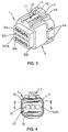
- Fig. 11 is a rear perspective view of a retainer for the press-fit block;
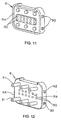
- Fig. 12 is a front perspective view of the retainer;
- Fig. 13 is a front elevational view of a multihole wire seal for the press-fit block;
- Fig. 14 is a side elevational view of the multihole wire seal;
- Fig. 15 is a sectional view taken along line 15-15 of Fig. 13;
- Fig. 16 is a front elevational view of a receptacle connector for the multipole waterproof connector;
- Fig. 17 is a sectional view of the receptacle connector; and
- Fig. 18 is a perspective view of a cable for a conventional multipole waterproof connector.
-
- In Figs. 1 and 2(1)-(6), the multipole water-proof connector consists of a plug connector A and a receptacle connector B. The plug connector A comprises a
connector body 1, a press-fit block 2, a large number of cables (wires) 3. Theconnector body 1 comprises aconnector housing 7 and a plurality of press-fit terminals 8 attached to theconnector housing 7. The press-fit block 2 comprises aorganizing protector 4, amultihole wire seal 5, and aretainer 6 for preventing bending. - In Figs. 3-5, the
connector housing 7 has aplugging projection 32 at the front end and a fitting recess 10 at the rear end and a lock section 11 on the top surface. Threerecesses 33 extend rearwardly from thefront face 32a of theplugging projection terminal insertion slots 34 extend rearwardly from thefront face 32a and are arranged laterally in two rows above and below the threerecesses 33 at regular intervals. Threeprojections 12 extend rearwardly from theend face 10A of thefitting recess 10 and are arranged laterally at the center line. - 12 press-
fit terminals 8 are provided on theend face 10A in a zigzag fashion in two rows above and below the threeprojections 12. As best shown in Fig. 5, the press-fit sections 8c of the press-fit terminals 8 extend into thefitting recess 10. The bifurcatedcontact points 8a of the press-fit terminals 8 extend into theplugging projection 32 such that thethroat portions 8b of thecontact points 8a align with the matingterminal insertion slots 34. A pair ofretainer receiving sections 13 are provided at the opening of thefitting recess 10. A pair ofengaging holes 14 are provided on the walls of theretainer receiving sections 13. The lock section 11 comprises a pair of guidingridges 15, acantilevered lock lever 16 disposed between them, and a pair oflock projections 17 extending laterally from thelock lever 16. - As best shown in Figs. 8 and 10(1)-(2), the
organizing protector 4 has a rectangular protector body 4A. 12cable insertion apertures 18 are provided in therear face 4a of theprotector body 4A in two rows with a constant pitch. Sixspacer fitting recesses 19 are provided on therear face 4a in two rows above and below thecable insertion apertures 18. Threerecesses 20 are provided on thefront face 4b of theprotective body 4A at the center line with a predetermined interval. Fourcable insertion apertures 18 are provided for each of the threerecesses 20. A pair of groups of six longitudinalcable insertion slots lower faces recesses 20, respectively, corresponding to thecable insertion apertures 18. - A pair of groups of six lateral
cable insertion slots front face 4b of theprotective body 4A at upper and lower positions, respectively, communicating with the longitudinalcable insertion apertures terminals insertion slots 23 are provided in thefront face 4b of theprotector body 4A so as to traverse the upper and lower lateralcable insertion slots - As best shown in Figs. 13-15, the
multihole wire seal 5 has a rectangular seal body 5A made from silicon rubber. 12cable insertion apertures 24 are provided in theface 5a of theseal body 5 in two rows. Six spacer fittingholes 25 are provided in theface 5a in two rows above and below thecable insertion apertures 24, respectively. A plurality oflip portions 27 are provided at the periphery of the seal body 5A. A plurality oflip portions cable insertion apertures 24 and the spacer fittingholes 25, respectively, to provide waterproof for gaps between thecables 3 and theconnector housing 7. - As best shown in Figs. 11 and 12, the
retainer 6 has a rectangular retainer body 6A. 12cable insertion apertures 30 are provided in theface 6a of theretainer 6 in two rows. Sixspacers 31 extend forwardly from theface 6a in two rows above and below thecable insertion apertures 30. A plurality ofengaging projections 32 are provided on left and right side faces of theretainer body 6A to prevent themultihole wire seal 5 from deforming under an external force upon thecable 3. - The
multihole wire seal 5 is provided between theorganizing protector 4 and theretainer 6 such that thespacers 31 of theretainer 6 enter the spacer fittingholes 25 of the multihole wire seal and the ends of thespacers 31 fit in thespacer fitting recesses 19 of theorganizing protector 4 to thereby form the press-fit block 2. Themultihole wire seal 5 is pressed between theorganizing protector 4 and theretainer 6 so that it expand in the direction perpendicular to the compression direction. Consequently, thelip portions 27 of the seal body 5A project outwardly, and thelip portions cable insertion apertures 24 and thespacer fitting apertures 25 project inwardly. Theorganizing protector 4 and theretainer 6 may be molded integrally. In this case, there is provided a separate seal between themultihole wire seal 5 and theconnector housing 7. Theorganizing protector 4, theretainer 6, and themultihole wire seal 5 may be molded integrally. - Figs. 2(1)-(6) show how 12
cables 3 are connected to the press-fit block 2. As best shown in Figs. 2(1)-(2), 12cables 3 are inserted intocable insertion apertures 18 of the organizingprotector 4 via thecable insertion apertures 24 of themultihole wire seal 5 and thecable insertion apertures 30 of theretainer 6, and thecables 3 are inserted into the longitudinalcable insertion slots end portions 3a of thecables 3 project from the organizingprotector 4. Then, as shown in Fig. 2(3), theend portions 3a of thecables 3 are bent into the lateralcable insertion slots excessive end portions 3b are cut off. - Then, as shown in Fig. 2(5), the press-
fit block 2 is press-fitted into thefitting recess 10 of theconnector body 1 such that the press-fit portions 8c of the press-fit terminals 8 are inserted intoinsertion slots 23 and press-fitted to thecables 3 to connect thecables 3 to the press-fit terminals 8 while theretainer 6 is inserted into theinsertion section 13 of theconnector housing 1 such that the engagingprojection 32 of theretainer 6 engage the engagingholes 14 of theretainer insertion section 13 to thereby form a plug connector A. - The
lip portions 27 of the seal body 5A are pressed against thefitting recess 10 of theconnector housing 1 while thelop portions 28 of thecable insertion apertures 24 are pressed against thecables 3, and thelip portions 29 of the spacerfitting apertures 25 are pressed against thespacer 31 to thereby provide waterproof. - A plurality of
projections 12 are provided on the end face of theconnector housing 7 and a plurality ofrecesses 20 are provided in thefront face 4b of theprotector body 4A. A plurality ofcable insertion apertures 18 are provided in the bottom of therecesses 20 and a plurality of longitudinalcable insertion slots lower faces recesses 20. The longitudinalcable insertion slots cable insertion slots cables 3 in thecable insertion apertures 18 are inserted into the longitudinalcable insertion slots end portions 3a of thecables 3 projecting from the organizingprotector 4 are bent into the lateralcable insertion slots fit block 2 is press-fitted into theconnector housing 7, theprojections 12 of theconnector housing 7 are inserted into therecesses 20 to hold thecables 3 in therecesses 20 thereby increasing the pulling resistance of thecables 3. - As shown in Figs. 16 and 17, the receptacle connector B has a
connector housing 40 which has a pluggingrecess 41 at the front end and a mountingsection 42 at the rear end. A attachingflange 43 is provided at the periphery of theconnector housing 40. Alock section 44 is provided at the upper wall 41a of the pluggingrecess 41 and comprises a lockinggroove 45 and a pair of engagingprojections 45A. Threeprojections 45 are provided on theend face 41A of the pluggingrecess 41 and a plurality of tab terminals (contact terminals) 46 are provided at upper and lower positions of theprojections 45. The leads 46a of thetab terminals 46 project from theboard mounting section 42. A seal attaching portion 47 is provided at the periphery of theend face 41A for receiving anannular seal member 48. - A pair of attaching
sections 49 with attachingholes 49a are provided in the attachingflange 43. Acontinuous seal groove 50 is provided in the attachingflange 43 for receiving a seal member (panel seal) 51. The receptacle connector B is mounted on a printedcircuit board 52 by inserting and soldering theleads 46a to the through-hole 53 and the seal member (panel seal) 51 is pressed against thefront panel 55 of aequipment case 54. - By plugging the plugging
section 32 of the plug connector A into the pluggingrecess 41 of the receptacle connector B, thetab terminals 46 of the receptacle connector B are inserted into the matingterminal insertion slots 34 of the pluggingsection 32 to bring them into contact with thecontact points 8a of the press-fit terminals 8 while thelock lever 16 of the plug connector A is inserted into thelock groove 45 of thereceptacle connector 13 to engage thelock projections 17 with the engagingprojections 45A for making lock. Thus, the pluggingsection 32 of the plug connector A is brought into contact with theseal member 48 for making seal. - A plurality of
cables 3 are connected to the press-fit block 2 and the press-fit block 2 is fitted into theconnector housing 7 such that the press-fit portions 8c of the press-fit terminals 8 are press-fitted to thecables 3 to provide a multipole waterproof connector, thereby making not only en-bloc but also automatic connection of thecables 3 possible. Themultihole wire seal 5 is provided between the organizingprotector 4 and theretainer 6 such that thespacers 31 are inserted into the spacer fitting holes 25 of themultihole wire seal 5 to fit the ends of thespacers 31 into the spacer fitting recesses 19, thereby improving assembling of the press-fit block 2 and the connection of thecables 3. - According to the invention, a plurality of cables are attached to the press-fit block, and the press-fit block is fitted into the connector housing such that the press-fit portions of the press-fit terminals are press-fitted to the cables to thereby make a compact multipole waterproof connector, making possible not only en-bloc connection of the cables but also automated connection of the cables, thus reducing amounts of labor.
- The wire seal is provided between the organizing protector and the retainer such that the spacers are fitted in the fitting holes of the wire seal and the ends of the spacers are fitted into the recesses of the organizing protector to make the press-fit block so that it is easy to assemble the press-fit block and connect the cables to the connector. The wire seal is held between the organizing protector and the retainer such that the lip portions of the wire seal are pressed against the inside wall of the connector housing and the lip portions of the cable insertion apertures are pressed against the cables, and lip portions of the spacer fitting holes are pressed against the spacers, thereby improving the waterproof property.
- A plurality of projections are provided on the end face of the fitting recess in the connector housing and a plurality of recesses are provided in the protector body, and a plurality of cable insertion apertures in the bottom of the recess and a plurality of longitudinal cable insertion slots are provided on the side wall of the recess such that the cable insertion slots are communicated with the lateral cable insertion slots of the protector body, the cables in the cable insertion apertures are inserted into the longitudinal cable insertion slots, and the ends of the cables are bent into the lateral cable insertion slots. When the press-fit block is fitted into the connector housing, the projections of the connector housing enter the recesses to hold the cables in the recesses so that the pulling resistance of the cables are enhanced.
Claims (5)
- A multipole waterproof connector comprising:a connector housing having a plugging projection and a fitting recess;at least one press-fit terminal attached to said connector housing such that a contact point and a press-fit portion of said press-fit terminal are on sides of said plugging projection and said fitting recess, respectively; a press-fit block having a wire seal around at least one cable insertion aperture;at least one cable put through said cable insertion aperture and bent at an end into said press-fit block;said press-fit block being fitted into said connector housing such that said press-fit portion of said press-fit terminal is press-fitted to said cable.
- A multipole waterproof connector comprising:a connector housing having a plugging projection and a fitting recess;at least one press-fit terminal such that a contact point and a press-fit portion of said press-fit terminal are on sides of said plugging projection and said fitting recess, respectively;a press-fit block consisting of an organizing protector having at least one cable insertion slot, a wire seal, and retainer provided in this order such that cable insertion apertures of said organizing protector, said wire seal, and said retainer communicate with each other;at least one cable put through said cable insertion apertures and bent at one end into said cable insertion slot of said organizing protector;said press-fit block being fit into said connector housing such that said press-fit portion of said press-fit terminal is press-fitted to said cable.
- A multipole waterproof connector according to claim 2, wherein said retainer has at least one spacer and said wire seal has at least one spacer fitting hole, and said organizing protector has a spacer fitting recess such that an end of said spacer is fitted in said spacer fitting recess through said spacer fitting hole.
- A multipole waterproof connector according to claim 3, wherein said wire seal has at least one lip portion at a side wall, at least one lip portion around said cable insertion aperture, and at least one lip portion around said spacer fitting hole such that when said wire seal is held between said organizing protector and said retainer, said lip portions are pressed against an inside wall of said connector housing, said cable, and said spacer, respectively.
- A multipole waterproof connector according to claim 3, wherein said connector housing has at least one projection provided on a bottom of said fitting recess and said organizing protector has at least one recess through which said cable insertion aperture extends, at least one longitudinal cable insertion slot on a side of said recess and at least lateral cable insertion slot on said organizing protector communicating with said longitudinal cable insertion slot such that said cable in said cable insertion aperture is inserted into said longitudinal cable insertion slot and bent into said lateral cable insertion slot and, when said press-fit block is fitted into said connector housing, said projection enters said recess to hold said cable in said recess.
Applications Claiming Priority (3)
| Application Number | Priority Date | Filing Date | Title |
|---|---|---|---|
| JP29921998 | 1998-10-21 | ||
| JP29921998A JP3313329B2 (en) | 1998-10-21 | 1998-10-21 | Multi-pole waterproof connector |
| US09/421,408 US6116952A (en) | 1998-10-21 | 1999-10-21 | Multipole waterproof connector |
Publications (3)
| Publication Number | Publication Date |
|---|---|
| EP0996200A2 true EP0996200A2 (en) | 2000-04-26 |
| EP0996200A3 EP0996200A3 (en) | 2002-01-23 |
| EP0996200B1 EP0996200B1 (en) | 2005-08-31 |
Family
ID=26561832
Family Applications (1)
| Application Number | Title | Priority Date | Filing Date |
|---|---|---|---|
| EP99121057A Expired - Lifetime EP0996200B1 (en) | 1998-10-21 | 1999-10-21 | Multipole waterproof connector |
Country Status (3)
| Country | Link |
|---|---|
| US (1) | US6116952A (en) |
| EP (1) | EP0996200B1 (en) |
| JP (1) | JP3313329B2 (en) |
Cited By (1)
| Publication number | Priority date | Publication date | Assignee | Title |
|---|---|---|---|---|
| EP1780836A2 (en) * | 2005-10-28 | 2007-05-02 | Hirschmann Automation and Control Gmbh | Sealing means for a connector and connector |
Families Citing this family (14)
| Publication number | Priority date | Publication date | Assignee | Title |
|---|---|---|---|---|
| JP4064537B2 (en) * | 1998-06-30 | 2008-03-19 | 矢崎総業株式会社 | Rear cover and method for forming elastic seal member in rear cover |
| JP2000133369A (en) * | 1998-10-27 | 2000-05-12 | Yazaki Corp | Waterproof connector and its assembling method |
| ATE251807T1 (en) * | 2000-03-30 | 2003-10-15 | Harting Kgaa | ELECTRICAL CONNECTOR FOR CONNECTING ELECTRICAL CONDUCTORS TO AN ELECTRICAL DEVICE |
| US6464523B1 (en) * | 2001-05-18 | 2002-10-15 | Northrop Grumman Corporation | Watertight electrical cable connector |
| US7048563B2 (en) * | 2003-04-23 | 2006-05-23 | Yazaki Corporation | Waterproof connector |
| JP2005222816A (en) * | 2004-02-05 | 2005-08-18 | Jst Mfg Co Ltd | Waterproof connector |
| US7101196B1 (en) * | 2005-05-18 | 2006-09-05 | Molex Incorporated | Sealed electrical connector assembly |
| US7201604B1 (en) * | 2006-03-16 | 2007-04-10 | John Mezzalingua Associates, Inc. | Ethernet cable connector and methods of use thereof |
| JP4800904B2 (en) * | 2006-02-22 | 2011-10-26 | 矢崎総業株式会社 | connector |
| US7878841B2 (en) * | 2009-02-24 | 2011-02-01 | John Mezzalingua Associates, Inc. | Pull through modular jack and method of use thereof |
| US7850481B2 (en) * | 2009-03-05 | 2010-12-14 | John Mezzalingua Associates, Inc. | Modular jack and method of use thereof |
| US8579772B2 (en) * | 2010-01-08 | 2013-11-12 | BVP Holdings, Inc. | Dynamic lower-body contour trainer and exercise machine |
| DE102011106853A1 (en) * | 2011-07-05 | 2013-01-10 | Wago Verwaltungsgesellschaft Mbh | Built-in connector |
| FR2994619B1 (en) * | 2012-08-17 | 2016-07-08 | Socapex Amphenol | ELECTRICAL CONNECTOR FOR HIGH FLOW |
Citations (7)
| Publication number | Priority date | Publication date | Assignee | Title |
|---|---|---|---|---|
| EP0440305A1 (en) * | 1990-01-30 | 1991-08-07 | E.I. Du Pont De Nemours And Company | Connector with fluid-sealing means |
| US5435747A (en) * | 1991-02-25 | 1995-07-25 | N.V. Raychem S.A. | Electrically-protected connector |
| EP0731531A2 (en) * | 1995-03-07 | 1996-09-11 | The Whitaker Corporation | Electrical connector having gel sealing and post insertion conductor engagement |
| US5632653A (en) * | 1995-04-06 | 1997-05-27 | Yazaki Corporation | Waterproof connector |
| JPH09289057A (en) * | 1996-04-19 | 1997-11-04 | Yazaki Corp | Waterproof connector |
| JPH10125408A (en) * | 1996-10-17 | 1998-05-15 | Dai Ichi Denshi Kogyo Kk | Connector device |
| CA2233189A1 (en) * | 1997-03-25 | 1998-09-25 | Plasticos Mondragon, S.A. | Perfected protection and cutting unit by flap cover, for connection and testing modules of telephone lines |
Family Cites Families (5)
| Publication number | Priority date | Publication date | Assignee | Title |
|---|---|---|---|---|
| JP2725758B2 (en) * | 1993-10-27 | 1998-03-11 | 矢崎総業株式会社 | Dummy plug for waterproof connector and waterproof connector |
| US5490785A (en) * | 1994-10-28 | 1996-02-13 | Alcoa Fujikura Limited | Automotive splice connector |
| US5871373A (en) * | 1996-02-23 | 1999-02-16 | Labinal Components And Systems, Inc. | Electrical connector |
| US5720629A (en) * | 1996-10-16 | 1998-02-24 | The Whitaker Corporation | Sealed electrical connector |
| US6039596A (en) * | 1997-11-10 | 2000-03-21 | The Whitaker Corporation | Gaskets for power cable tap connector |
-
1998
- 1998-10-21 JP JP29921998A patent/JP3313329B2/en not_active Expired - Fee Related
-
1999
- 1999-10-21 EP EP99121057A patent/EP0996200B1/en not_active Expired - Lifetime
- 1999-10-21 US US09/421,408 patent/US6116952A/en not_active Expired - Fee Related
Patent Citations (7)
| Publication number | Priority date | Publication date | Assignee | Title |
|---|---|---|---|---|
| EP0440305A1 (en) * | 1990-01-30 | 1991-08-07 | E.I. Du Pont De Nemours And Company | Connector with fluid-sealing means |
| US5435747A (en) * | 1991-02-25 | 1995-07-25 | N.V. Raychem S.A. | Electrically-protected connector |
| EP0731531A2 (en) * | 1995-03-07 | 1996-09-11 | The Whitaker Corporation | Electrical connector having gel sealing and post insertion conductor engagement |
| US5632653A (en) * | 1995-04-06 | 1997-05-27 | Yazaki Corporation | Waterproof connector |
| JPH09289057A (en) * | 1996-04-19 | 1997-11-04 | Yazaki Corp | Waterproof connector |
| JPH10125408A (en) * | 1996-10-17 | 1998-05-15 | Dai Ichi Denshi Kogyo Kk | Connector device |
| CA2233189A1 (en) * | 1997-03-25 | 1998-09-25 | Plasticos Mondragon, S.A. | Perfected protection and cutting unit by flap cover, for connection and testing modules of telephone lines |
Cited By (2)
| Publication number | Priority date | Publication date | Assignee | Title |
|---|---|---|---|---|
| EP1780836A2 (en) * | 2005-10-28 | 2007-05-02 | Hirschmann Automation and Control Gmbh | Sealing means for a connector and connector |
| EP1780836A3 (en) * | 2005-10-28 | 2007-08-01 | Hirschmann Automation and Control Gmbh | Sealing means for a connector and connector |
Also Published As
| Publication number | Publication date |
|---|---|
| JP3313329B2 (en) | 2002-08-12 |
| EP0996200A3 (en) | 2002-01-23 |
| US6116952A (en) | 2000-09-12 |
| EP0996200B1 (en) | 2005-08-31 |
| JP2000133365A (en) | 2000-05-12 |
Similar Documents
| Publication | Publication Date | Title |
|---|---|---|
| US4588242A (en) | Sealed electrical connector | |
| US7410386B2 (en) | Pluggable screwless wire connector system | |
| EP2164137B1 (en) | A joint connector, joint terminal, a wiring harness with a joint connector and method of assembling it | |
| US5380220A (en) | Connector | |
| EP0996200B1 (en) | Multipole waterproof connector | |
| US4653825A (en) | Shielded electrical connector assembly | |
| US6966798B1 (en) | Jack with foolproof member for selectively restricting plug insertion | |
| US4653836A (en) | Shielded electrical connector | |
| EP0806814A2 (en) | Electrical connector having terminals with improved retention means | |
| EP0971442A1 (en) | A connector with a side type retainer | |
| EP0156539A1 (en) | Keying system and method of keying for electrical connectors | |
| US5626499A (en) | Connector | |
| EP0014037B1 (en) | Electrical connector for flat cable | |
| US6283793B1 (en) | Electrical connector system | |
| EP0795930B1 (en) | High contact force pin-receiving electrical contact | |
| US6129574A (en) | Connector having a construction for preventing an erroneous assembling of a connector housing and a cover | |
| US6210237B1 (en) | Multi-port modular jack assembly and method for making the same | |
| US20020086586A1 (en) | Cable connector assembly | |
| US20100144188A1 (en) | Electric connector with a dust cover | |
| EP1204177B1 (en) | Board mount type connector and connector board mounting structure | |
| EP0043200B1 (en) | Electrical connector assembly with releasably retained terminals | |
| US6019641A (en) | Electric connector | |
| CA2242287C (en) | Connector | |
| US4863400A (en) | Electrical connector | |
| US4726792A (en) | Electrical connector having electrical contacts provided with retention means |
Legal Events
| Date | Code | Title | Description |
|---|---|---|---|
| PUAI | Public reference made under article 153(3) epc to a published international application that has entered the european phase |
Free format text: ORIGINAL CODE: 0009012 |
|
| AK | Designated contracting states |
Kind code of ref document: A2 Designated state(s): AT BE CH CY DE DK ES FI FR GB GR IE IT LI LU MC NL PT SE Kind code of ref document: A2 Designated state(s): DE FR GB IT |
|
| AX | Request for extension of the european patent |
Free format text: AL;LT;LV;MK;RO;SI |
|
| PUAL | Search report despatched |
Free format text: ORIGINAL CODE: 0009013 |
|
| AK | Designated contracting states |
Kind code of ref document: A3 Designated state(s): AT BE CH CY DE DK ES FI FR GB GR IE IT LI LU MC NL PT SE |
|
| AX | Request for extension of the european patent |
Free format text: AL;LT;LV;MK;RO;SI |
|
| 17P | Request for examination filed |
Effective date: 20020627 |
|
| AKX | Designation fees paid |
Free format text: DE FR GB IT |
|
| 17Q | First examination report despatched |
Effective date: 20040913 |
|
| GRAP | Despatch of communication of intention to grant a patent |
Free format text: ORIGINAL CODE: EPIDOSNIGR1 |
|
| GRAS | Grant fee paid |
Free format text: ORIGINAL CODE: EPIDOSNIGR3 |
|
| GRAA | (expected) grant |
Free format text: ORIGINAL CODE: 0009210 |
|
| AK | Designated contracting states |
Kind code of ref document: B1 Designated state(s): DE FR GB IT |
|
| REG | Reference to a national code |
Ref country code: GB Ref legal event code: FG4D |
|
| REF | Corresponds to: |
Ref document number: 69926968 Country of ref document: DE Date of ref document: 20051006 Kind code of ref document: P |
|
| ET | Fr: translation filed | ||
| PLBE | No opposition filed within time limit |
Free format text: ORIGINAL CODE: 0009261 |
|
| STAA | Information on the status of an ep patent application or granted ep patent |
Free format text: STATUS: NO OPPOSITION FILED WITHIN TIME LIMIT |
|
| 26N | No opposition filed |
Effective date: 20060601 |
|
| PGFP | Annual fee paid to national office [announced via postgrant information from national office to epo] |
Ref country code: GB Payment date: 20061025 Year of fee payment: 8 |
|
| PGFP | Annual fee paid to national office [announced via postgrant information from national office to epo] |
Ref country code: FR Payment date: 20061027 Year of fee payment: 8 Ref country code: DE Payment date: 20061027 Year of fee payment: 8 |
|
| PGFP | Annual fee paid to national office [announced via postgrant information from national office to epo] |
Ref country code: IT Payment date: 20071029 Year of fee payment: 9 |
|
| GBPC | Gb: european patent ceased through non-payment of renewal fee |
Effective date: 20071021 |
|
| PG25 | Lapsed in a contracting state [announced via postgrant information from national office to epo] |
Ref country code: DE Free format text: LAPSE BECAUSE OF NON-PAYMENT OF DUE FEES Effective date: 20080501 |
|
| REG | Reference to a national code |
Ref country code: FR Ref legal event code: ST Effective date: 20080630 |
|
| PG25 | Lapsed in a contracting state [announced via postgrant information from national office to epo] |
Ref country code: GB Free format text: LAPSE BECAUSE OF NON-PAYMENT OF DUE FEES Effective date: 20071021 |
|
| PG25 | Lapsed in a contracting state [announced via postgrant information from national office to epo] |
Ref country code: FR Free format text: LAPSE BECAUSE OF NON-PAYMENT OF DUE FEES Effective date: 20071031 |
|
| PG25 | Lapsed in a contracting state [announced via postgrant information from national office to epo] |
Ref country code: IT Free format text: LAPSE BECAUSE OF NON-PAYMENT OF DUE FEES Effective date: 20081021 |