EP0996023B2 - Progressive addition lenses - Google Patents
Progressive addition lenses Download PDFInfo
- Publication number
- EP0996023B2 EP0996023B2 EP99308360A EP99308360A EP0996023B2 EP 0996023 B2 EP0996023 B2 EP 0996023B2 EP 99308360 A EP99308360 A EP 99308360A EP 99308360 A EP99308360 A EP 99308360A EP 0996023 B2 EP0996023 B2 EP 0996023B2
- Authority
- EP
- European Patent Office
- Prior art keywords
- lens
- progressive addition
- maximum
- dioptric
- astigmatism
- Prior art date
- Legal status (The legal status is an assumption and is not a legal conclusion. Google has not performed a legal analysis and makes no representation as to the accuracy of the status listed.)
- Expired - Lifetime
Links
- 0 C=C1CC=*=CC1 Chemical compound C=C1CC=*=CC1 0.000 description 2
Images


Classifications
-
- G—PHYSICS
- G02—OPTICS
- G02C—SPECTACLES; SUNGLASSES OR GOGGLES INSOFAR AS THEY HAVE THE SAME FEATURES AS SPECTACLES; CONTACT LENSES
- G02C7/00—Optical parts
- G02C7/02—Lenses; Lens systems ; Methods of designing lenses
- G02C7/04—Contact lenses for the eyes
-
- G—PHYSICS
- G02—OPTICS
- G02C—SPECTACLES; SUNGLASSES OR GOGGLES INSOFAR AS THEY HAVE THE SAME FEATURES AS SPECTACLES; CONTACT LENSES
- G02C7/00—Optical parts
- G02C7/02—Lenses; Lens systems ; Methods of designing lenses
- G02C7/06—Lenses; Lens systems ; Methods of designing lenses bifocal; multifocal ; progressive
- G02C7/061—Spectacle lenses with progressively varying focal power
- G02C7/068—Special properties achieved by the combination of the front and back surfaces
-
- B—PERFORMING OPERATIONS; TRANSPORTING
- B29—WORKING OF PLASTICS; WORKING OF SUBSTANCES IN A PLASTIC STATE IN GENERAL
- B29D—PRODUCING PARTICULAR ARTICLES FROM PLASTICS OR FROM SUBSTANCES IN A PLASTIC STATE
- B29D11/00—Producing optical elements, e.g. lenses or prisms
- B29D11/00009—Production of simple or compound lenses
- B29D11/00028—Bifocal lenses; Multifocal lenses
-
- B—PERFORMING OPERATIONS; TRANSPORTING
- B29—WORKING OF PLASTICS; WORKING OF SUBSTANCES IN A PLASTIC STATE IN GENERAL
- B29D—PRODUCING PARTICULAR ARTICLES FROM PLASTICS OR FROM SUBSTANCES IN A PLASTIC STATE
- B29D11/00—Producing optical elements, e.g. lenses or prisms
- B29D11/00009—Production of simple or compound lenses
- B29D11/00432—Auxiliary operations, e.g. machines for filling the moulds
-
- B—PERFORMING OPERATIONS; TRANSPORTING
- B29—WORKING OF PLASTICS; WORKING OF SUBSTANCES IN A PLASTIC STATE IN GENERAL
- B29D—PRODUCING PARTICULAR ARTICLES FROM PLASTICS OR FROM SUBSTANCES IN A PLASTIC STATE
- B29D11/00—Producing optical elements, e.g. lenses or prisms
- B29D11/0073—Optical laminates
-
- G—PHYSICS
- G02—OPTICS
- G02C—SPECTACLES; SUNGLASSES OR GOGGLES INSOFAR AS THEY HAVE THE SAME FEATURES AS SPECTACLES; CONTACT LENSES
- G02C7/00—Optical parts
- G02C7/02—Lenses; Lens systems ; Methods of designing lenses
- G02C7/06—Lenses; Lens systems ; Methods of designing lenses bifocal; multifocal ; progressive
- G02C7/061—Spectacle lenses with progressively varying focal power
Definitions
- the present invention relates to multifocal ophthalmic lenses.
- the invention provides progressive addition lenses in which unwanted lens astigmatism is reduced without functional compromise of the distance and channel widths through the intermediate and near vision zones, as compared to conventional progressive addition lenses.
- ophthalmic lenses for the correction of ametropia
- multifocal lenses such as progressive addition lenses (“PAL's")
- PAL's progressive addition lenses
- the surface of a PAL provides far, intermediate, and near vision in a gradual, continuous progression of vertically increasing dioptric power from far to near focus, or top to bottom of the lens.
- PAL's are appealing to the wearer because PAL's are free of the visible ledges between the zones of differing dioptric power that are found in other multifocal lenses, such as bifocals and trifocals.
- an inherent disadvantage in PAL's is unwanted lens astigmatism, or astigmatism introduced or caused by one or more of the lens' surfaces.
- the unwanted lens astigmatism is located on either side of the near vision zone of the lens and, at or near its approximate center, reaches a maximum level that corresponds approximately to the near vision dioptric add power of the lens.
- a PAL with a 2.00 diopter add power and 15 mm channel length will have about a 2.00 diopter maximum, localized unwanted astigmatism.
- the channel width of the lens will be approximately 6 mm in which the unwanted astigmatism is less than or equal to a 0.75 diopter threshold value.
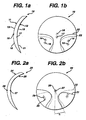
- FIG. 1a is a side view of a lens of the invention.
- FIG. 1b is an astigmatism map of the lens of FIG. 1a
- FIG. 2a is a side view of a lens of the invention.
- FIG. 2b is an astigmatism map of the lens of FIG. 2a .
- FIG. 3 is a side view of a lens of the invention.
- FIG. 4a is a side view of the lens of the invention.
- FIG. 4b is an astigmatism map of the lens of FIG. 4a
- FIG. 5a is a side view of a lens of the invention.
- FIG. 5b is an astigmatism map of a progressive surface of the lens of FIG. 5a .
- FIG. 5c is an astigmatism map of a progressive surface of the lens of FIG. 5a .
- FIG. 5d is an astigmatism map of the lens of FIG. 5a .
- the present invention provides progressive addition lenses, as well as methods for their design and production, in which the maximum, localized unwanted astigmatism that is associated with a given dioptric add power is reduced compared to prior art lenses. Additionally, the distance width, or width about the optical center of the lens that is free of about 0.50 diopters or more of unwanted astigmatism, and minimum channel width of the lens is suitable for use by the lens wearer.
- channel is meant the corridor of vision that is free of astigmatism of about 0.75 diopters or greater when the wearer's eye is scanning from the distance zone to the near zone and back.
- lens or “lenses” is meant any ophthalmic lens including, without limitation, spectacle lenses, contact lenses, intraocular lenses and the like.
- the lens of the invention is a spectacle lens.
- maximum, localized astigmatism may be reduced by combining two or more progressive addition surfaces each providing a dioptric add power that combines with that of the other surface or surfaces to produce a lens of a higher dioptric add power than that of the surfaces individually.
- dioptric add power is meant the amount of dioptric power difference between the near and far vision zones of a progressive addition surface.
- the lens of the invention exhibits less maximum, localized unwanted astigmatism and a wider channel than would be expected by producing a lens with the same dioptric add power using only a single progressive addition surface.
- the use of more than one progressive addition surface ensures that the distance dioptric power and the total dioptric add power needed to correct the wearer's vision are uncompromised. It is yet another discovery of the invention that when the progressive surfaces' dioptric add power areas are misaligned with respect to one another, the resultant total maximum, localized unwanted astigmatism of the lens is less than the sum of the maximum, localized unwanted astigmatism contributed by the individual dioptric add powers of each progressive addition surface.
- progressive addition surface is meant a continuous, aspheric surface having far and near vision zones and a zone of increasing dioptric power connecting the far and near vision zones.
- maximum, localized unwanted astigmatism is meant the highest, measurable level of astigmatism in an area of unwanted astigmatism on a lens surface.
- the lens of the invention comprises, consists essentially of, and consists of: a.) a first progressive addition surface having one or more areas of maximum, localized unwanted astigmatism and a first dioptric add power; and b.) a second progressive addition surface having one or more areas of maximum, localized unwanted astigmatism and a second dioptric add power, the progressive addition surfaces disposed in relation to each other so that a portion or all of the areas of maximum, localized unwanted astigmatism are misaligned and wherein the dioptric add power of the lens is the sum of the first and second dioptric add powers.
- the invention provides a process for producing a lens comprising, consisting essentially of, and consisting of the steps of: a.) providing at least a first and a second progressive addition surface, the first progressive addition surface having one or more areas of maximum, localized unwanted astigmatism and a first dioptric add power and the second progressive addition surface having one or more areas of maximum, localized unwanted astigmatism and a second dioptric add power; and b.) disposing the first and second progressive addition surfaces so that a portion or all of the areas of maximum, localized unwanted astigmatism are misaligned and the dioptric add power of the lens is the sum of the first and second dioptric add powers.
- misalignd is meant that the surfaces, and thus the areas of unwanted astigmatism, are arranged or disposed in relation to one another so that a portion or all of the areas of maximum, localized unwanted astigmatism of one surface do not substantially coincide with one or more areas of maximum, localized unwanted astigmatism of the other surface.
- the misalignment is such that no area of maximum, localized unwanted astigmatism of a surface substantially coincides with that of the other surface.
- the progressive addition surfaces used in the lens of the invention may be misaligned by any of a number of methods.
- the optical centers of the surfaces may be shifted either or both laterally or vertically with respect to each other.
- optical center is meant the point on a surface intersected by the optical axis of the lens.
- a progressive addition lens design using a lateral shift preferably uses progressive addition surfaces with wider channel widths to compensate for the diminution in channel width caused by the shift.
- channel length is meant the distance along the central meridian of the surface between the optical center and the top end of the near vision zone.
- each surface is designed so that it is asymmetric about the center line of its channel. In this case, the areas of maximum, localized unwanted astigmatism of the surfaces do not substantially coincide on rotation of the optics about an axis joining the surfaces' optical centers.
- asymmetric is meant that the power and astigmatism maps of the surface are asymmetric about the center meridian of the surface.
- the lateral and vertical shifts are done in such a way as to preserve the distance and near vision dioptric powers of the lens.
- the shifts In order to minimize the introduction of lens prism power, the shifts must occur so that the optical center of one progressive addition surface is shifted along a curve that is parallel to the distance curve of the other progressive addition surface.
- the surfaces In the case of rotations, the surfaces are rotated about their optical centers so that the distance and near powers are substantially unaffected.
- the rotational misalignment may be in addition to the misalignment carried out for purposes of reducing unwanted astigmatism.
- the amount of misalignment, or the vertical shift, lateral shift or rotation of optical centers is an amount sufficient to prevent substantial superposition, or coincidence, of the maximum, localized unwanted astigmatism areas of the progressive addition surfaces. More specifically, it is believed that the misalignment leads to a mismatch of the direction of the astigmatic vectors associated with one surface relative to the corresponding astigmatic vectors of the other surface resulting in the total maximum, localized unwanted astigmatism for the final lens being less than that if the vectors were aligned.
- the lateral or vertical shift may be about 0.1 mm to about 10 mm, preferably about 1.0 mm to about 8 mm, more preferably about 2.0 mm to about 4.0 mm.
- Rotational shifts may be about 1 to about 40 degrees, preferably about 5 to about 30 degrees, more preferably about 10 to about 20 degrees.
- each surface may be designed so that the channel length of the surfaces are of different lengths.
- the areas of maximum, localized, unwanted astigmatism of the surfaces do not align when the optical centers of the surfaces are brought into alignment.
- the unwanted astigmatism is reduced compared to a lens of the same total dioptric add power.
- the greater the difference between the channel lengths the greater will be the reduction in maximum, localized unwanted astigmatism.
- the channel lengths must not be so large as to produce a mismatch in the near vision zones so that the near vision of the lens wearer is compromised.
- the lens resulting from this embodiment will have a channel length falling between that of each surface and dependent upon the dioptric add power contributed by each surface to the total dioptric add power of the lens.
- the channel length difference between the surfaces may be about 0.1 mm to about 10 mm, preferably about 1 mm to about 7 mm, more preferably about 2 mm to about 5 mm.
- the progressive addition surfaces may each be independently on the convex or concave surface of the lens or in a layer between the outer concave and outer convex surfaces of the lens.
- Other surfaces such as spheric and toric surfaces, designed to adapt the lens to the ophthalmic prescription of the lens' wearer may be used in combination with, or in addition to, one or more of the progressive addition surfaces.
- a progressive addition surface may be combined with a toric surface, such as concave surface that is a progressive addition surface and has a cylinder power at a particular axis.
- a dioptric add power and cylinder power need not be provided at every axis combination desired for the lens. Rather, it has been discovered that, because dioptric add power decreases relatively slowly when one moves horizontally away from the center of the add zone to the lens periphery, a rotational misalignment of surfaces of up to about + or -25, preferably + or - 20, more preferably + or - 15 degrees may be used while still achieving the desired dioptric add power for the lens.
- the dioptric add power of each of the progressive addition surfaces used in the invention is selected so that the sum of their dioptric add powers is substantially equal to the value needed to correct the lens wearer's near vision acuity.
- the dioptric add power of each surface is selected in view of the maximum, localized unwanted astigmatism associated with a given near dioptric power.
- the dioptric add power of the progressive addition surfaces may be each independently from about + 0.01 diopters to about +3.00 diopters, preferably from about +0.25 diopters to about +2.00 diopters, more preferably about +0.50 to about +1.50 diopters.
- the distance and near dioptric powers for each surface are selected so that the sum of the powers is the value needed to correct the wearer's distance and near vision.
- the distance dioptric power for each surface will be within the range of about 0.25 diopters to about 8.50 diopters.
- the dioptric power of the distance zone of the concave surface may be + or - about 2.00 to about 5.50 diopters and for the convex surface, + or - about 0.5 to about 8.00 diopters.
- the near vision dioptric power for each of the surfaces will be about 1.00 diopters to about 12.00 diopters.
- the progressive addition surfaces and lenses of the invention may be formed by any convenient method such as, without limitation, thermoforming, molding, grinding, casting or the like.
- an optical preform having a progressive addition surface is used and a second progressive addition surface is cast onto the preform.
- a preform the concave surface of which is a progressive addition surface with a base spherical power and a cylinder power is used and a progressive addition surface is formed on the front surface by any convenient method, preferably by casting and more preferably by surface casting.
- lens 10 of the invention is shown having convex progressive addition surface 11 and concave progressive addition surface 12.
- Surface 11 has distance zone 13 with a curvature of 6.00 diopters and near zone 18 with a curvature of 7.00 diopters.
- Surface 12 has distance zone 19 with a curvature of 6.00 diopters and near zone 21 with a curvature of 5.00 diopters.
- the resulting distance power of the lens is 0.00 diopters and the dioptric add power of the lens is 2.00 diopters, 1.00 diopters contributed by each of surfaces 11 and 12.
- the convex and concave optical centers 16 and 17, respectively, are shifted with respect to each other by 4.0 mm.
- FIG. 1b is an astigmatism map of lens 10 illustrating the misalignment of the surfaces. Areas 22 and 23 are of the unwanted astigmatism for surfaces 11 and 12, respectively. The locations of the maximum, localized astigmatism 14 and 15 do not overlap and, thus, are not additive. The maximum, localized unwanted astigmatism value of 1.90 D for this lens is shown in Table 1 and is significantly lower than the 2.20 D that is found in a conventional PAL of the same near dioptric power. Table 1 Example Add Power Front (D) Add Power Back (D) Add Power Total (D) Vertical Shift (mm) Max. Astigmatism (D) Max. Astig./Add Ratio Prior Art 2.00 0.00 2.00 0.0 2.20 1.10 1 1.05 1.05 2.10 4.0 1.90 0.90 2 1.05 1.05 2.10 8.0 1.90 0.90
- a lens with two progressive addition surfaces is used, the misalignment for which is 8.00 mm.
- the misalignment results in a reduction of maximum localized unwanted astigmatism of 0.30 D compared to the prior art Lens of Table 1.
- lens 20 with a concave progressive addition surface 25 is seen.
- Surface 25 has distance and near zone curvatures of 6.00 and 5.00 diopters, respectively.
- Convex surface 24 with distance and near zone curvatures of 6.00 and 7.00 diopters is also shown.
- the optical center 27 of surface 25 is rotated by ⁇ , an amount of 10 degrees, with respect to that of optical center 26 of convex progressive surface 24.
- FIG. 2b the astigmatism map of lens 20 is shown. Areas 31 and 32 depict the areas of unwanted astigmatism for surfaces 24 and 25, respectively. Maximum, localized unwanted astigmatism areas 28 and 29 for surfaces 24 and 25, respectively, are also shown.
- Table 2 shows that the resulting lens has a maximum, localized unwanted astigmatism of 1.90 diopters as compared to 2.10 diopters for a prior art lens.
- Table 2 Example Add Power Front (D) Add Power Back (D) Add Power Total (D) Rotational Shift (deg.) Max. Astigmatism (D) Max. Astig./Add Ratio Prior Art 2.00 0.00 2.00 0.0 2.20 1.10 3 1.00 1.00 1.90 10.0 1.90 1.00 4 1.00 1.00 1.95 20.0 1.85 0.95 5 1.00 1.00 1.85 30.0 1.75 0.95 6 1.00 1.00 1.85 40.0 1.41 0.76
- the concave progressive addition surface of a lens is rotated around its optical center by 20, 30, and 40 degrees with respect to the convex progressive addition surface.
- the rotations result in maximum, localized unwanted astigmatisms of 1.85, 1.75, and 1.41 diopters, respectively as listed on Table 2.
- FIG. 3 depicts a concave progressive addition surface 34 placed between surfaces 33 and 35 of lens 30.
- Lens 30 is made of an optical preform 38 having a refractive index of 1.60 and a cast layer 39 having a refractive index of 1.50.
- Convex surface 33 of preform 38 has optical center 36, a distance curvature of 6.50 diopters and a near curvature of 8.50 diopters.
- Optical center 37 is shifted vertically downwards 4 mm with respect to optical center 36.
- Concave surface 35 of layer 39 includes a cylindrical power of -2.00 D for correcting the wearer's astigmatism.
- Lens 30 has a distance power of 0.00 diopters, a total dioptric add power of 3.00 diopters, arrived at by the 2.00 diopter dioptric add power of surface 33 and the 1.00 diopters dioptric add power of surface 34 combined.
- the maximum, localized unwanted astigmatism is lower than that of a conventional lens with a 3.00 diopters dioptric add power.
- FIG. 4a depicted lens 50 having convex surface 51 and concave surface 52.
- Surface 51 is a progressive addition surface with optical center 53.
- Surface 52 is a combination progressive addition-toric surface having optical center 54 shifted vertically downwards 4 mm with respect to optical center 53.
- FIG. 4b depicts the astigmatism map for lens 50 showing the shift. Areas 55 and 56 are the areas of unwanted astigmatism, 57 and 58 being their respective maximum, localized unwanted astigmatism areas respectively, for surfaces 51 and 52.
- I-I is the toric axis for surface 52.
- the overlap of the progressive addition surfaces are such that, although the near and distance vision zones are preserved, the location of the maximum, localized unwanted astigmatisms 57 and 58 of each surface do not coincide and, thus, their effect is not additive.
- Lens 60 is depicted in FIG. 5a in which a left oriented, convex progressive addition surface 61 shown combined with a right oriented, concave progressive addition surface 62. Each surface is depicted individually in FIGs. 5b and 5c , respectively. Optical centers 63 and 64 of each surface are rotated so as to become optically aligned. In FIG. 5d is depicted that the left and right orientation of the surfaces provides misalignment of the unwanted astigmatism areas 65 and 66 of surfaces 61 and 62, respectively.
- Table 3 Example Add Power Front (D) Add Power Back (D) Add Power Total (D) Max. Astigmatism (D) Max. Astig./Add Ratio Prior Art 2.02 0.00 2.02 2.20 1.10 9 1.00L 1.00R 2.10 1.70 0.81
- An optical preform is produced containing a spherical convex surface with a curvature of 6.00 diopters.
- the preform's concave surface is a toric progressive surface with a base spherical curvature of 6.00 diopters, a cylinder curvature of 4.00 diopters at an axis placed at the 0-180 axis, and a near vision zone with an add power of 1.00.
- the near vision zone is placed on the concave toric surface of the preform at 11.25 degrees clockwise from the bottom of the lens (the 270 degree axis).
- the resultant preform has a 0.00 diopter distance power, a -2.00 diopter cylinder power at an axis of 0 degrees and a 1.00 diopter add power.
- a progressive addition glass mold with a 6.00 diopter base curvature and a 1.00 diopter add power placed at the 270 degree axis is used to surface cast a UV curable resin layer on the convex surface of the preform using conventional surface casting techniques.
- the resultant lens has a distance power of 0.00 diopters, a cylinder of-2.00 diopters at 0 degree axis, an add power of 2.00 diopters.
- the 11.25 degree misalignment of the front and back add powers results in a reduction of maximum, localized unwanted astigmatism relative to a prior art lens.
Abstract
Description
- The present invention relates to multifocal ophthalmic lenses. In particular, the invention provides progressive addition lenses in which unwanted lens astigmatism is reduced without functional compromise of the distance and channel widths through the intermediate and near vision zones, as compared to conventional progressive addition lenses.
- The use of ophthalmic lenses for the correction of ametropia is well known. For example, multifocal lenses, such as progressive addition lenses ("PAL's"), are used for the treatment of presbyopia. The surface of a PAL provides far, intermediate, and near vision in a gradual, continuous progression of vertically increasing dioptric power from far to near focus, or top to bottom of the lens.
- PAL's are appealing to the wearer because PAL's are free of the visible ledges between the zones of differing dioptric power that are found in other multifocal lenses, such as bifocals and trifocals. However, an inherent disadvantage in PAL's is unwanted lens astigmatism, or astigmatism introduced or caused by one or more of the lens' surfaces. Generally, the unwanted lens astigmatism is located on either side of the near vision zone of the lens and, at or near its approximate center, reaches a maximum level that corresponds approximately to the near vision dioptric add power of the lens.
- Generally, a PAL with a 2.00 diopter add power and 15 mm channel length will have about a 2.00 diopter maximum, localized unwanted astigmatism. The channel width of the lens will be approximately 6 mm in which the unwanted astigmatism is less than or equal to a 0.75 diopter threshold value.
- Any number of lens designs have been tried in attempting to either or both reduce unwanted astigmatism or increase the minimum channel width, e.g. that of
US 5 726 734 . However, current state-of-the-art progressive addition lenses provide only minimal decreases in unwanted astigmatism while having large areas in the lenses' peripheries that are unusable due to unwanted astigmatism. Thus, a need exists for a PAL that reduces maximum, localized unwanted astigmatism and, at the same time, provides an increase in the minimum channel width. This problem is solved by the features of the lens according to claim 1 produced by the method according toclaim 10. -
FIG. 1a is a side view of a lens of the invention. -
FIG. 1b is an astigmatism map of the lens ofFIG. 1a -
FIG. 2a is a side view of a lens of the invention. -
FIG. 2b is an astigmatism map of the lens ofFIG. 2a . -
FIG. 3 is a side view of a lens of the invention. -
FIG. 4a is a side view of the lens of the invention. -
FIG. 4b is an astigmatism map of the lens ofFIG. 4a -
FIG. 5a is a side view of a lens of the invention. -
FIG. 5b is an astigmatism map of a progressive surface of the lens ofFIG. 5a . -
FIG. 5c is an astigmatism map of a progressive surface of the lens ofFIG. 5a . -
FIG. 5d is an astigmatism map of the lens ofFIG. 5a . - The present invention provides progressive addition lenses, as well as methods for their design and production, in which the maximum, localized unwanted astigmatism that is associated with a given dioptric add power is reduced compared to prior art lenses. Additionally, the distance width, or width about the optical center of the lens that is free of about 0.50 diopters or more of unwanted astigmatism, and minimum channel width of the lens is suitable for use by the lens wearer.
- For purposes of the invention, by "channel" is meant the corridor of vision that is free of astigmatism of about 0.75 diopters or greater when the wearer's eye is scanning from the distance zone to the near zone and back. By "lens" or "lenses" is meant any ophthalmic lens including, without limitation, spectacle lenses, contact lenses, intraocular lenses and the like. Preferably, the lens of the invention is a spectacle lens.
- It is one discovery of the invention that maximum, localized astigmatism may be reduced by combining two or more progressive addition surfaces each providing a dioptric add power that combines with that of the other surface or surfaces to produce a lens of a higher dioptric add power than that of the surfaces individually. By "dioptric add power" is meant the amount of dioptric power difference between the near and far vision zones of a progressive addition surface. The lens of the invention exhibits less maximum, localized unwanted astigmatism and a wider channel than would be expected by producing a lens with the same dioptric add power using only a single progressive addition surface. Further, it is a discovery of the invention that the use of more than one progressive addition surface ensures that the distance dioptric power and the total dioptric add power needed to correct the wearer's vision are uncompromised. It is yet another discovery of the invention that when the progressive surfaces' dioptric add power areas are misaligned with respect to one another, the resultant total maximum, localized unwanted astigmatism of the lens is less than the sum of the maximum, localized unwanted astigmatism contributed by the individual dioptric add powers of each progressive addition surface.
- By "progressive addition surface" is meant a continuous, aspheric surface having far and near vision zones and a zone of increasing dioptric power connecting the far and near vision zones. By "maximum, localized unwanted astigmatism" is meant the highest, measurable level of astigmatism in an area of unwanted astigmatism on a lens surface.
- In one embodiment, the lens of the invention comprises, consists essentially of, and consists of: a.) a first progressive addition surface having one or more areas of maximum, localized unwanted astigmatism and a first dioptric add power; and b.) a second progressive addition surface having one or more areas of maximum, localized unwanted astigmatism and a second dioptric add power, the progressive addition surfaces disposed in relation to each other so that a portion or all of the areas of maximum, localized unwanted astigmatism are misaligned and wherein the dioptric add power of the lens is the sum of the first and second dioptric add powers.
- In another embodiment, the invention provides a process for producing a lens comprising, consisting essentially of, and consisting of the steps of: a.) providing at least a first and a second progressive addition surface, the first progressive addition surface having one or more areas of maximum, localized unwanted astigmatism and a first dioptric add power and the second progressive addition surface having one or more areas of maximum, localized unwanted astigmatism and a second dioptric add power; and b.) disposing the first and second progressive addition surfaces so that a portion or all of the areas of maximum, localized unwanted astigmatism are misaligned and the dioptric add power of the lens is the sum of the first and second dioptric add powers.
- By "misaligned" is meant that the surfaces, and thus the areas of unwanted astigmatism, are arranged or disposed in relation to one another so that a portion or all of the areas of maximum, localized unwanted astigmatism of one surface do not substantially coincide with one or more areas of maximum, localized unwanted astigmatism of the other surface. Preferably, the misalignment is such that no area of maximum, localized unwanted astigmatism of a surface substantially coincides with that of the other surface.
- The progressive addition surfaces used in the lens of the invention may be misaligned by any of a number of methods. For example, the optical centers of the surfaces may be shifted either or both laterally or vertically with respect to each other. By "optical center" is meant the point on a surface intersected by the optical axis of the lens. One ordinarily skilled in the art will recognize that, if the optical centers are shifted laterally, the minimum channel width is reduced by the extent of the shift. Thus, a progressive addition lens design using a lateral shift preferably uses progressive addition surfaces with wider channel widths to compensate for the diminution in channel width caused by the shift.
- Alternatively, if the optical centers of the surfaces are shifted vertically, the channel length will be increased. By "channel length is meant the distance along the central meridian of the surface between the optical center and the top end of the near vision zone. Thus, a design using such a shift preferably uses progressive addition surfaces with shorter channel lengths in compensation.
- As yet another alternative, maintaining the optical centers of the progressive surfaces coincident with each other, the centers may be rotated with respect to one another. In a preferred embodiment, each surface is designed so that it is asymmetric about the center line of its channel. In this case, the areas of maximum, localized unwanted astigmatism of the surfaces do not substantially coincide on rotation of the optics about an axis joining the surfaces' optical centers. By "asymmetric" is meant that the power and astigmatism maps of the surface are asymmetric about the center meridian of the surface.
- The lateral and vertical shifts are done in such a way as to preserve the distance and near vision dioptric powers of the lens. In order to minimize the introduction of lens prism power, the shifts must occur so that the optical center of one progressive addition surface is shifted along a curve that is parallel to the distance curve of the other progressive addition surface. In the case of rotations, the surfaces are rotated about their optical centers so that the distance and near powers are substantially unaffected. One ordinarily skilled in the art will recognize that the rotational misalignment may be in addition to the misalignment carried out for purposes of reducing unwanted astigmatism.
- The amount of misalignment, or the vertical shift, lateral shift or rotation of optical centers, is an amount sufficient to prevent substantial superposition, or coincidence, of the maximum, localized unwanted astigmatism areas of the progressive addition surfaces. More specifically, it is believed that the misalignment leads to a mismatch of the direction of the astigmatic vectors associated with one surface relative to the corresponding astigmatic vectors of the other surface resulting in the total maximum, localized unwanted astigmatism for the final lens being less than that if the vectors were aligned. The lateral or vertical shift may be about 0.1 mm to about 10 mm, preferably about 1.0 mm to about 8 mm, more preferably about 2.0 mm to about 4.0 mm. Rotational shifts may be about 1 to about 40 degrees, preferably about 5 to about 30 degrees, more preferably about 10 to about 20 degrees.
- As yet another alternative for misalignment, each surface may be designed so that the channel length of the surfaces are of different lengths. In this embodiment, the areas of maximum, localized, unwanted astigmatism of the surfaces do not align when the optical centers of the surfaces are brought into alignment. As a result, the unwanted astigmatism is reduced compared to a lens of the same total dioptric add power. The greater the difference between the channel lengths, the greater will be the reduction in maximum, localized unwanted astigmatism. However, the channel lengths must not be so large as to produce a mismatch in the near vision zones so that the near vision of the lens wearer is compromised. The lens resulting from this embodiment will have a channel length falling between that of each surface and dependent upon the dioptric add power contributed by each surface to the total dioptric add power of the lens. The channel length difference between the surfaces may be about 0.1 mm to about 10 mm, preferably about 1 mm to about 7 mm, more preferably about 2 mm to about 5 mm.
- The progressive addition surfaces may each be independently on the convex or concave surface of the lens or in a layer between the outer concave and outer convex surfaces of the lens. Other surfaces, such as spheric and toric surfaces, designed to adapt the lens to the ophthalmic prescription of the lens' wearer may be used in combination with, or in addition to, one or more of the progressive addition surfaces.
- For example, a progressive addition surface may be combined with a toric surface, such as concave surface that is a progressive addition surface and has a cylinder power at a particular axis. In this case, a dioptric add power and cylinder power need not be provided at every axis combination desired for the lens. Rather, it has been discovered that, because dioptric add power decreases relatively slowly when one moves horizontally away from the center of the add zone to the lens periphery, a rotational misalignment of surfaces of up to about + or -25, preferably + or - 20, more preferably + or - 15 degrees may be used while still achieving the desired dioptric add power for the lens.
- The dioptric add power of each of the progressive addition surfaces used in the invention is selected so that the sum of their dioptric add powers is substantially equal to the value needed to correct the lens wearer's near vision acuity.
- Additionally, the dioptric add power of each surface is selected in view of the maximum, localized unwanted astigmatism associated with a given near dioptric power. The dioptric add power of the progressive addition surfaces may be each independently from about + 0.01 diopters to about +3.00 diopters, preferably from about +0.25 diopters to about +2.00 diopters, more preferably about +0.50 to about +1.50 diopters.
- Similarly, the distance and near dioptric powers for each surface are selected so that the sum of the powers is the value needed to correct the wearer's distance and near vision. Generally, the distance dioptric power for each surface will be within the range of about 0.25 diopters to about 8.50 diopters. Preferably, the dioptric power of the distance zone of the concave surface may be + or - about 2.00 to about 5.50 diopters and for the convex surface, + or - about 0.5 to about 8.00 diopters. The near vision dioptric power for each of the surfaces will be about 1.00 diopters to about 12.00 diopters.
- The progressive addition surfaces and lenses of the invention may be formed by any convenient method such as, without limitation, thermoforming, molding, grinding, casting or the like. In a preferred method, an optical preform having a progressive addition surface is used and a second progressive addition surface is cast onto the preform. In a more preferred method, a preform the concave surface of which is a progressive addition surface with a base spherical power and a cylinder power is used and a progressive addition surface is formed on the front surface by any convenient method, preferably by casting and more preferably by surface casting.
- The invention will be clarified further by a consideration of the following, non-limiting examples.
- Referring to
FIG. 1a ,lens 10 of the invention is shown having convexprogressive addition surface 11 and concaveprogressive addition surface 12.Surface 11 hasdistance zone 13 with a curvature of 6.00 diopters and nearzone 18 with a curvature of 7.00 diopters.Surface 12 hasdistance zone 19 with a curvature of 6.00 diopters and nearzone 21 with a curvature of 5.00 diopters. The resulting distance power of the lens is 0.00 diopters and the dioptric add power of the lens is 2.00 diopters, 1.00 diopters contributed by each ofsurfaces FIG. 1a , the convex and concaveoptical centers -
FIG. 1b is an astigmatism map oflens 10 illustrating the misalignment of the surfaces.Areas surfaces localized astigmatism Table 1 Example Add Power Front (D) Add Power Back (D) Add Power Total (D) Vertical Shift
(mm)Max. Astigmatism
(D)Max. Astig./Add Ratio Prior Art 2.00 0.00 2.00 0.0 2.20 1.10 1 1.05 1.05 2.10 4.0 1.90 0.90 2 1.05 1.05 2.10 8.0 1.90 0.90 - A lens with two progressive addition surfaces is used, the misalignment for which is 8.00 mm. The misalignment results in a reduction of maximum localized unwanted astigmatism of 0.30 D compared to the prior art Lens of Table 1.
- As shown in
FIGs. 2a and 2b ,lens 20 with a concaveprogressive addition surface 25 is seen.Surface 25 has distance and near zone curvatures of 6.00 and 5.00 diopters, respectively.Convex surface 24 with distance and near zone curvatures of 6.00 and 7.00 diopters is also shown. Theoptical center 27 ofsurface 25 is rotated by α, an amount of 10 degrees, with respect to that ofoptical center 26 of convexprogressive surface 24. InFIG. 2b , the astigmatism map oflens 20 is shown.Areas surfaces unwanted astigmatism areas surfaces Table 2 Example Add Power Front (D) Add Power Back (D) Add Power Total (D) Rotational Shift (deg.) Max. Astigmatism
(D)Max. Astig./Add Ratio Prior Art 2.00 0.00 2.00 0.0 2.20 1.10 3 1.00 1.00 1.90 10.0 1.90 1.00 4 1.00 1.00 1.95 20.0 1.85 0.95 5 1.00 1.00 1.85 30.0 1.75 0.95 6 1.00 1.00 1.85 40.0 1.41 0.76 - The concave progressive addition surface of a lens is rotated around its optical center by 20, 30, and 40 degrees with respect to the convex progressive addition surface. The rotations result in maximum, localized unwanted astigmatisms of 1.85, 1.75, and 1.41 diopters, respectively as listed on Table 2.
-
FIG. 3 depicts a concaveprogressive addition surface 34 placed betweensurfaces lens 30.Lens 30 is made of anoptical preform 38 having a refractive index of 1.60 and acast layer 39 having a refractive index of 1.50.Convex surface 33 ofpreform 38 hasoptical center 36, a distance curvature of 6.50 diopters and a near curvature of 8.50 diopters.Concave surface 34 ofpreform 38 hasoptical center 37, a distance curvature ("DC") of 6.50 diopters and a near curvature ("NC") of 0.50 diopters derived by the formula:
optical preform 38 and n2 is the refractive index oflayer 39.Optical center 37 is shifted vertically downwards 4 mm with respect tooptical center 36.Concave surface 35 oflayer 39 includes a cylindrical power of -2.00 D for correcting the wearer's astigmatism.Lens 30 has a distance power of 0.00 diopters, a total dioptric add power of 3.00 diopters, arrived at by the 2.00 diopter dioptric add power ofsurface 33 and the 1.00 diopters dioptric add power ofsurface 34 combined. The maximum, localized unwanted astigmatism is lower than that of a conventional lens with a 3.00 diopters dioptric add power. - In
FIG. 4a is depictedlens 50 havingconvex surface 51 andconcave surface 52.Surface 51 is a progressive addition surface withoptical center 53.Surface 52 is a combination progressive addition-toric surface havingoptical center 54 shifted vertically downwards 4 mm with respect tooptical center 53.FIG. 4b depicts the astigmatism map forlens 50 showing the shift.Areas surfaces surface 52. The overlap of the progressive addition surfaces are such that, although the near and distance vision zones are preserved, the location of the maximum, localizedunwanted astigmatisms -
Lens 60 is depicted inFIG. 5a in which a left oriented, convexprogressive addition surface 61 shown combined with a right oriented, concaveprogressive addition surface 62. Each surface is depicted individually inFIGs. 5b and 5c , respectively.Optical centers FIG. 5d is depicted that the left and right orientation of the surfaces provides misalignment of theunwanted astigmatism areas surfaces lens 60 of 1.70 diopters listed on Table 3.Table 3 Example Add Power Front
(D)Add Power Back
(D)Add Power Total
(D)Max. Astigmatism
(D)Max. Astig./Add Ratio Prior Art 2.02 0.00 2.02 2.20 1.10 9 1.00L 1.00R 2.10 1.70 0.81 - An optical preform is produced containing a spherical convex surface with a curvature of 6.00 diopters. The preform's concave surface is a toric progressive surface with a base spherical curvature of 6.00 diopters, a cylinder curvature of 4.00 diopters at an axis placed at the 0-180 axis, and a near vision zone with an add power of 1.00. The near vision zone is placed on the concave toric surface of the preform at 11.25 degrees clockwise from the bottom of the lens (the 270 degree axis). The resultant preform has a 0.00 diopter distance power, a -2.00 diopter cylinder power at an axis of 0 degrees and a 1.00 diopter add power. A progressive addition glass mold with a 6.00 diopter base curvature and a 1.00 diopter add power placed at the 270 degree axis is used to surface cast a UV curable resin layer on the convex surface of the preform using conventional surface casting techniques. The resultant lens has a distance power of 0.00 diopters, a cylinder of-2.00 diopters at 0 degree axis, an add power of 2.00 diopters. The 11.25 degree misalignment of the front and back add powers results in a reduction of maximum, localized unwanted astigmatism relative to a prior art lens.
Claims (5)
- A lens, such as a spectacle lens, comprising a first progressive addition surface having one or more areas of maximum, localized unwanted astigmatism and a first dioptric add power and second progressive addition surface having one or more areas of maximum, localized unwanted astigmatism and a second dioptric add power, the progressive addition surfaces disposed in relation to each other so that a portion or all areas of maximum, localized unwanted astigmatism are misaligned and wherein the dioptric add power of the lens is about the sum of the first and second dioptric add powers wherein by "progressive addition surface" is meant a continuous, aspheric surface having far and near vision zones and a zone of increasing dioptric power connecting the far and near vision zone.
- The lens of claim 1, wherein the progressive addition surfaces are asymmetric.
- The lens of any one of claims 1 to 2, further comprising a concave surface and a convex surface, the first progressive addition surface being on the concave surface and the second progressive addition surface being on the convex surface.
- The lens of any one of claims 1 to 2, further comprising a concave surface, a convex surface, and a layer there-between, the first progressive addition surface being on the concave surface or the convex surface and the second progressive addition surface being in the layer between the concave and convex surfaces.
- A process for producing a lens comprising the steps of:providing at least a first and a second progressive addition surface, the first progressive addition surface having one or more areas of maximum, localized unwanted astigmatism and a first dioptric add power and the second progressive addition surface having one or more areas of maximum, localized unwanted astigmatism and a second dioptric add power; anddisposing the first and second progressive addition surfaces so that all or a portion of the areas of maximum, localized unwanted astigmatism are misaligned and the dioptric add power of the lens is about the sum of the first and second dioptric add powers where in by "progressive addition surface" is meant a continuous, aspheric surface having far and near vision zones and a zone of increasing dioptric power connecting the far and near vision zone.
Applications Claiming Priority (2)
| Application Number | Priority Date | Filing Date | Title |
|---|---|---|---|
| US09/178,471 US6149271A (en) | 1998-10-23 | 1998-10-23 | Progressive addition lenses |
| US178471 | 1998-10-23 |
Publications (4)
| Publication Number | Publication Date |
|---|---|
| EP0996023A2 EP0996023A2 (en) | 2000-04-26 |
| EP0996023A3 EP0996023A3 (en) | 2000-09-13 |
| EP0996023B1 EP0996023B1 (en) | 2002-12-11 |
| EP0996023B2 true EP0996023B2 (en) | 2010-04-07 |
Family
ID=22652665
Family Applications (1)
| Application Number | Title | Priority Date | Filing Date |
|---|---|---|---|
| EP99308360A Expired - Lifetime EP0996023B2 (en) | 1998-10-23 | 1999-10-22 | Progressive addition lenses |
Country Status (15)
| Country | Link |
|---|---|
| US (2) | US6149271A (en) |
| EP (1) | EP0996023B2 (en) |
| JP (2) | JP4955846B2 (en) |
| KR (1) | KR100640183B1 (en) |
| CN (1) | CN1169007C (en) |
| AT (1) | ATE229657T1 (en) |
| AU (1) | AU754265B2 (en) |
| BR (1) | BR9905589B1 (en) |
| CA (1) | CA2287058C (en) |
| DE (1) | DE69904423T3 (en) |
| IL (1) | IL132467A (en) |
| MY (1) | MY116050A (en) |
| RU (1) | RU2231996C2 (en) |
| SG (1) | SG83750A1 (en) |
| TW (1) | TW470854B (en) |
Families Citing this family (54)
| Publication number | Priority date | Publication date | Assignee | Title |
|---|---|---|---|---|
| AUPO903197A0 (en) * | 1997-09-09 | 1997-10-02 | Sola International Holdings Ltd | Improved progressive lens |
| US6199984B1 (en) * | 1999-03-17 | 2001-03-13 | Johnson & Johnson Vision Care, Inc. | Progressive addition lenses with varying power profiles |
| US6106118A (en) * | 1999-09-05 | 2000-08-22 | Johnson & Johnson Vision Products, Inc. | Progressive addition lenses |
| WO2001025837A1 (en) * | 1999-10-01 | 2001-04-12 | Sola International Holdings Ltd | Progressive lens |
| AU772399B2 (en) * | 1999-10-01 | 2004-04-29 | Carl Zeiss Vision Australia Holdings Ltd | Progressive lens |
| US6231184B1 (en) * | 1999-11-12 | 2001-05-15 | Johnson & Johnson Vision Care, Inc. | Progressive addition lenses |
| US6398946B1 (en) * | 1999-12-22 | 2002-06-04 | Chevron U.S.A., Inc. | Process for making a lube base stock from a lower molecular weight feedstock |
| DE10104700A1 (en) * | 2001-02-02 | 2002-10-02 | Rodenstock Optik G | Process for the representation and optimization of a double progressive spectacle lens |
| JP4246422B2 (en) * | 2001-09-11 | 2009-04-02 | セイコーオプティカルプロダクツ株式会社 | Progressive power spectacle lens design method and manufacturing method |
| DE10211033A1 (en) * | 2002-03-13 | 2003-09-25 | Rodenstock Gmbh | Progressive spectacle lens has two non-spherical surfaces and especially progressive surfaces |
| JP3617004B2 (en) * | 2002-05-28 | 2005-02-02 | Hoya株式会社 | Double-sided aspherical progressive-power lens |
| ATE414930T1 (en) * | 2002-05-28 | 2008-12-15 | Hoya Corp | DOUBLE-SIDED ASPHERIC VARIFOCAL POWER LENS |
| JP4030814B2 (en) * | 2002-07-10 | 2008-01-09 | ペンタックス株式会社 | Multifocal spectacle lens and manufacturing method thereof |
| US6923540B2 (en) * | 2002-07-31 | 2005-08-02 | Novartis Ag | Toric multifocal contact lenses |
| WO2004034129A1 (en) * | 2002-10-04 | 2004-04-22 | Carl Zeiss Ag | Method for production of a lens and lens produced thus |
| DE10252814A1 (en) * | 2002-11-13 | 2004-06-03 | Rodenstock Gmbh | Double progressive glasses |
| DE10253130A1 (en) * | 2002-11-14 | 2004-06-03 | Rodenstock Gmbh | Double progressive glasses |
| AU2002953061A0 (en) * | 2002-11-20 | 2002-12-19 | Sola International Holdings Ltd | Method for designing progressive lenses |
| US7125118B2 (en) * | 2003-04-02 | 2006-10-24 | Seiko Epson Corporation | Progressive multifocal lens and method of designing the same |
| JP3582527B1 (en) * | 2003-04-10 | 2004-10-27 | セイコーエプソン株式会社 | Progressive power lens and manufacturing method |
| US7377638B2 (en) * | 2003-05-19 | 2008-05-27 | Essilor International (Compagnie Generale D'optique) | Four zone multifocal lenses |
| US6956682B2 (en) * | 2003-06-26 | 2005-10-18 | Johnson & Johnson Vision Care, Inc. | Method for designing progressive addition lenses |
| US7101042B2 (en) * | 2003-08-12 | 2006-09-05 | S.I.B. Investments Llc | Multifocal contact lens |
| DE10345214B4 (en) * | 2003-09-29 | 2007-09-06 | Rodenstock Gmbh | Series of progressive lenses with low divergence and rotation of the astigmatism |
| US7059718B2 (en) * | 2004-01-21 | 2006-06-13 | Hidden Harbor Group L.L.C. | Eyewear having a magnified wide field of view |
| FR2880428B1 (en) * | 2005-01-04 | 2007-10-26 | Essilor Int | PROGRESSIVE OPHTHALMIC GLASS AND METHOD OF MANUFACTURING SUCH A GLASS |
| EP1894058A2 (en) * | 2005-06-20 | 2008-03-05 | ESSILOR INTERNATIONAL Compagnie Générale d'Optique | Method for providing dual surface progressive addition lens series |
| JP4811875B2 (en) * | 2005-06-24 | 2011-11-09 | Hoya株式会社 | Double-sided aspherical progressive-power lens group design method and double-sided aspherical progressive-power lens group |
| US7258437B2 (en) * | 2005-09-07 | 2007-08-21 | Transitions Optical, Inc. | Photochromic multifocal optical article |
| TWI394789B (en) | 2005-12-22 | 2013-05-01 | Nippon Catalytic Chem Ind | Water-absorbent resin composition, method of manufacturing the same, and absorbent article |
| CN100456052C (en) * | 2005-12-30 | 2009-01-28 | 上海三联(集团)有限公司吴良材眼镜公司 | Office using gradual-change multi-focus lens |
| AR062067A1 (en) | 2006-07-17 | 2008-10-15 | Novartis Ag | TORICAS CONTACT LENSES WITH CONTROLLED OPTICAL POWER PROFILE |
| JP2010520514A (en) | 2007-03-07 | 2010-06-10 | ピクセルオプティクス, インコーポレイテッド | Multifocal lens with progressive optical power region and discontinuity |
| US20080273169A1 (en) * | 2007-03-29 | 2008-11-06 | Blum Ronald D | Multifocal Lens Having a Progressive Optical Power Region and a Discontinuity |
| TWI487516B (en) | 2007-08-22 | 2015-06-11 | Novartis Ag | Presbyopic treatment system |
| FR2920888B1 (en) | 2007-09-12 | 2010-10-15 | Essilor Int | REALIZING AN OPHTHALMIC GLASS FOR A BEARER |
| CA2704213A1 (en) * | 2007-10-30 | 2009-05-07 | Visionware Llc | Progressive reading and intermediate distance lens defined by employment of a zernike expansion |
| AU2008332369B2 (en) | 2007-12-04 | 2011-09-08 | Hoya Corporation | Pair of progressive power lens and method for designing same |
| WO2009150265A1 (en) * | 2008-06-13 | 2009-12-17 | Lopez Hernandez Reyes | Double-sided progressive lens |
| EP2149812B1 (en) * | 2008-07-31 | 2021-08-25 | Hoya Corporation | Progressive-addition lens, method for preparing shape data thereof, method for manufacturing the lens, and apparatus and computer program product for preparing such shape data |
| US7828433B2 (en) * | 2008-10-22 | 2010-11-09 | Shamir Optical Industry | Assymetrical progressive lens |
| EP2202561A1 (en) * | 2008-12-24 | 2010-06-30 | Essilor International (Compagnie Générale D'Optique) | A lens customizing method |
| RU2511711C2 (en) | 2009-01-30 | 2014-04-10 | Хойа Корпорейшн | Method of evaluating spectacle lens, method of designing spectacle lens and method of manufacturing spectacle lens |
| CN102548654A (en) | 2009-09-29 | 2012-07-04 | 株式会社日本触媒 | Particulate water absorbent and process for production thereof |
| EP2526455B1 (en) | 2010-01-18 | 2017-05-17 | Essilor International (Compagnie Générale D'Optique) | Process for designing an ophthalmic progressive eyeglass |
| US8042941B2 (en) * | 2010-01-29 | 2011-10-25 | Indizen Optical Technologies, S.I. | Lens with continuous power gradation |
| JP5725646B2 (en) * | 2010-03-10 | 2015-05-27 | ホーヤ レンズ マニュファクチャリング フィリピン インク | Progressive power lens design method, progressive power lens design system, and progressive power lens manufacturing method |
| JP2012013742A (en) * | 2010-06-29 | 2012-01-19 | Seiko Epson Corp | Progressive refractive power eyeglass lens and design method thereof |
| CN104204915B (en) * | 2012-03-23 | 2017-03-01 | Hoya株式会社 | The method for designing of eyeglass and eyeglass, manufacture method and manufacture system |
| TWI588560B (en) | 2012-04-05 | 2017-06-21 | 布萊恩荷登視覺協會 | Lenses, devices, methods and systems for refractive error |
| RU2510477C2 (en) * | 2012-04-06 | 2014-03-27 | Сергей Александрович Снигур | Projector with lens light flux former |
| US9201250B2 (en) | 2012-10-17 | 2015-12-01 | Brien Holden Vision Institute | Lenses, devices, methods and systems for refractive error |
| TWI600418B (en) | 2012-10-17 | 2017-10-01 | 布萊恩荷登視覺協會 | Lenses, devices, methods and systems for refractive error |
| CN106062616B (en) * | 2014-04-01 | 2019-04-12 | 依视路国际公司 | It is arranged to the multifocal ophthalmology spectacle lens for exporting supplemental image |
Family Cites Families (36)
| Publication number | Priority date | Publication date | Assignee | Title |
|---|---|---|---|---|
| GB775007A (en) * | 1953-09-21 | 1957-05-15 | John Henry Jeffree | Improvements in or relating to lenses |
| DE1805561C3 (en) * | 1967-10-30 | 1980-10-23 | Societe Des Lunetiers, Paris | Ophthalmic lens with strong refractive power and predetermined astigmatism |
| US3711191A (en) * | 1971-09-16 | 1973-01-16 | L Tagnon | Aberration corrected ophthalmic progressive power lenses |
| CA1012392A (en) * | 1973-08-16 | 1977-06-21 | American Optical Corporation | Progressive power ophthalmic lens |
| US4056311A (en) * | 1973-08-16 | 1977-11-01 | American Optical Corporation | Progressive power ophthalmic lens having a plurality of viewing zones with non-discontinuous variations therebetween |
| US4055379A (en) * | 1973-08-16 | 1977-10-25 | American Optical Corporation | Multifocal lens |
| FR2425653A1 (en) * | 1978-05-12 | 1979-12-07 | Essilor Int | PROCESS FOR DEVELOPING A REFRACTION SURFACE OF AN OPHTHALMIC LENS WITH PROGRESSIVELY VARIABLE FOCAL POWER |
| FR2481813A1 (en) * | 1980-04-30 | 1981-11-06 | Essilor Int | PROGRESSIVE OPHTHALMIC LENS |
| US4676610A (en) * | 1983-07-22 | 1987-06-30 | Sola International Holdings Ltd. | Method of making progressive lens surface and resulting article |
| DE3331757A1 (en) * | 1983-09-02 | 1985-05-23 | Optische Werke G. Rodenstock, 8000 München | Bilaterally aspherical progressive spectacle lens |
| DE3430334A1 (en) * | 1984-08-17 | 1986-02-27 | Optische Werke G. Rodenstock, 8000 München | PROGRESSIVE EYEWEAR WITH TWO ASPHERIC AREAS |
| US5771089A (en) * | 1984-08-17 | 1998-06-23 | Optische Werke G. Rodenstock | Progressive spectacle lens |
| DE3433916C2 (en) * | 1984-09-15 | 1986-10-16 | Optische Werke G. Rodenstock, 8000 München | Lens for half glasses |
| GB8528460D0 (en) * | 1985-11-19 | 1985-12-24 | Sola Int Holdings | Multifocal lens |
| DE3635777A1 (en) * | 1986-10-21 | 1988-05-05 | Rodenstock Optik G | PROGRESSIVE EYEWEAR |
| JP2519921B2 (en) * | 1987-04-13 | 1996-07-31 | セイコーエプソン株式会社 | Vision correction device using two progressive multifocal lenses |
| DE3716201C2 (en) * | 1987-05-14 | 2001-02-15 | Rodenstock Optik G | Progressive glasses |
| US4952048A (en) * | 1987-09-14 | 1990-08-28 | Opticorp, Inc. | Method of designing a non-progressive multifocal ophthalmic lens |
| US5178800A (en) * | 1990-10-10 | 1993-01-12 | Innotech, Inc. | Method for forming plastic optical quality spectacle lenses |
| US5219497A (en) * | 1987-10-30 | 1993-06-15 | Innotech, Inc. | Method for manufacturing lenses using thin coatings |
| DE3752164T2 (en) * | 1987-11-25 | 1998-08-06 | Hitoshi Okano | MULTIFOCAL LENS WITH A SEGMENT WITH PROGRESSIVE EFFECT |
| US4859261A (en) * | 1988-05-11 | 1989-08-22 | Ace Ronald S | Method of making multi-focus ophthalmic lens |
| US5305028A (en) * | 1990-04-24 | 1994-04-19 | Hitoshi Okano | Multifocal lens provided with progressive focal segment |
| US5455642A (en) * | 1990-12-27 | 1995-10-03 | Sieko Epson Corporation | Progressive power lens |
| JP2769931B2 (en) * | 1991-04-02 | 1998-06-25 | 利宜 白井 | Bifocal eyeglass lens |
| EP0578833A4 (en) * | 1992-02-03 | 1994-06-29 | Seiko Epson Corp | Variable focus visual power correction apparatus |
| US5644374A (en) * | 1992-02-03 | 1997-07-01 | Seiko Epson Corporation | Variable focus type eyesight correcting apparatus |
| JP3619264B2 (en) * | 1994-08-22 | 2005-02-09 | ペンタックス株式会社 | Progressive multifocal lens and its mold |
| US6019470A (en) * | 1995-11-24 | 2000-02-01 | Seiko Epson Corporation | Progressive multifocal lens and manufacturing method of eyeglass lens and progressive multifocal lens |
| DE69638108D1 (en) * | 1995-11-24 | 2010-02-25 | Seiko Epson Corp | Multi-strength glass for spectacles and spectacle lenses |
| US5812237A (en) * | 1995-11-27 | 1998-09-22 | Roddy; Kenneth C. | Ophthalmic no-line progressive addition lenses |
| US5726734A (en) * | 1996-01-19 | 1998-03-10 | American Optical Corporation | Hard/soft superposition progressive lens design |
| US5715032A (en) * | 1996-03-19 | 1998-02-03 | Optical Radiation Corporation | Progressive addition power ophthalmic lens |
| US5847803A (en) * | 1996-09-17 | 1998-12-08 | Innotech, Inc. | Optic incorporating a power gradient |
| US5793465A (en) * | 1996-10-08 | 1998-08-11 | Innotech, Inc. | Toric surfacecasting |
| DE19701312A1 (en) * | 1997-01-16 | 1998-07-23 | Zeiss Carl Fa | Spectacle lens with spherical front and multifocal back, and method for its production |
-
1998
- 1998-10-23 US US09/178,471 patent/US6149271A/en not_active Expired - Lifetime
-
1999
- 1999-05-20 US US09/315,477 patent/US6123422A/en not_active Expired - Lifetime
- 1999-10-19 IL IL13246799A patent/IL132467A/en not_active IP Right Cessation
- 1999-10-20 SG SG9905294A patent/SG83750A1/en unknown
- 1999-10-21 CA CA002287058A patent/CA2287058C/en not_active Expired - Lifetime
- 1999-10-21 MY MYPI99004543A patent/MY116050A/en unknown
- 1999-10-22 AU AU56028/99A patent/AU754265B2/en not_active Expired
- 1999-10-22 JP JP30166199A patent/JP4955846B2/en not_active Expired - Lifetime
- 1999-10-22 BR BRPI9905589-9A patent/BR9905589B1/en not_active IP Right Cessation
- 1999-10-22 AT AT99308360T patent/ATE229657T1/en not_active IP Right Cessation
- 1999-10-22 KR KR1019990045970A patent/KR100640183B1/en active IP Right Grant
- 1999-10-22 RU RU99122175/14A patent/RU2231996C2/en active
- 1999-10-22 DE DE69904423T patent/DE69904423T3/en not_active Expired - Lifetime
- 1999-10-22 EP EP99308360A patent/EP0996023B2/en not_active Expired - Lifetime
- 1999-10-23 CN CNB991254554A patent/CN1169007C/en not_active Expired - Lifetime
-
2000
- 2000-03-30 TW TW088118266A patent/TW470854B/en not_active IP Right Cessation
-
2010
- 2010-07-16 JP JP2010161763A patent/JP5200068B2/en not_active Expired - Lifetime
Also Published As
| Publication number | Publication date |
|---|---|
| BR9905589B1 (en) | 2010-11-16 |
| IL132467A0 (en) | 2001-03-19 |
| SG83750A1 (en) | 2001-10-16 |
| CA2287058C (en) | 2007-11-27 |
| DE69904423D1 (en) | 2003-01-23 |
| JP5200068B2 (en) | 2013-05-15 |
| DE69904423T2 (en) | 2003-04-17 |
| BR9905589A (en) | 2000-08-29 |
| ATE229657T1 (en) | 2002-12-15 |
| US6123422A (en) | 2000-09-26 |
| EP0996023A2 (en) | 2000-04-26 |
| JP2000155294A (en) | 2000-06-06 |
| AU5602899A (en) | 2000-05-04 |
| EP0996023B1 (en) | 2002-12-11 |
| JP2010237710A (en) | 2010-10-21 |
| KR20000029253A (en) | 2000-05-25 |
| CN1254850A (en) | 2000-05-31 |
| JP4955846B2 (en) | 2012-06-20 |
| KR100640183B1 (en) | 2006-10-31 |
| RU2231996C2 (en) | 2004-07-10 |
| AU754265B2 (en) | 2002-11-07 |
| MY116050A (en) | 2003-10-31 |
| CN1169007C (en) | 2004-09-29 |
| EP0996023A3 (en) | 2000-09-13 |
| CA2287058A1 (en) | 2000-04-23 |
| DE69904423T3 (en) | 2010-11-04 |
| US6149271A (en) | 2000-11-21 |
| IL132467A (en) | 2002-07-25 |
| TW470854B (en) | 2002-01-01 |
Similar Documents
| Publication | Publication Date | Title |
|---|---|---|
| EP0996023B2 (en) | Progressive addition lenses | |
| EP1379911B1 (en) | Progressive addition lenses | |
| EP1026533B1 (en) | Progressive addition lenses having regressive surfaces | |
| US6106118A (en) | Progressive addition lenses | |
| EP1063556B1 (en) | Methods for producing progressive addition lenses | |
| AU2002252366A1 (en) | Progressive addition lenses | |
| MXPA99009766A (en) | Progressive addition lenses | |
| MXPA99009764A (en) | Methods for producing progressive addition lenses |
Legal Events
| Date | Code | Title | Description |
|---|---|---|---|
| PUAI | Public reference made under article 153(3) epc to a published international application that has entered the european phase |
Free format text: ORIGINAL CODE: 0009012 |
|
| AK | Designated contracting states |
Kind code of ref document: A2 Designated state(s): AT BE CH CY DE DK ES FI FR GB GR IE IT LI LU MC NL PT SE |
|
| AX | Request for extension of the european patent |
Free format text: AL;LT;LV;MK;RO;SI |
|
| PUAL | Search report despatched |
Free format text: ORIGINAL CODE: 0009013 |
|
| AK | Designated contracting states |
Kind code of ref document: A3 Designated state(s): AT BE CH CY DE DK ES FI FR GB GR IE IT LI LU MC NL PT SE |
|
| AX | Request for extension of the european patent |
Free format text: AL;LT;LV;MK;RO;SI |
|
| 17P | Request for examination filed |
Effective date: 20010223 |
|
| AKX | Designation fees paid |
Free format text: AT BE CH CY DE DK ES FI FR GB GR IE IT LI LU MC NL PT SE |
|
| GRAG | Despatch of communication of intention to grant |
Free format text: ORIGINAL CODE: EPIDOS AGRA |
|
| 17Q | First examination report despatched |
Effective date: 20011112 |
|
| GRAG | Despatch of communication of intention to grant |
Free format text: ORIGINAL CODE: EPIDOS AGRA |
|
| GRAG | Despatch of communication of intention to grant |
Free format text: ORIGINAL CODE: EPIDOS AGRA |
|
| GRAH | Despatch of communication of intention to grant a patent |
Free format text: ORIGINAL CODE: EPIDOS IGRA |
|
| GRAH | Despatch of communication of intention to grant a patent |
Free format text: ORIGINAL CODE: EPIDOS IGRA |
|
| GRAA | (expected) grant |
Free format text: ORIGINAL CODE: 0009210 |
|
| AK | Designated contracting states |
Kind code of ref document: B1 Designated state(s): AT BE CH CY DE DK ES FI FR GB GR IE IT LI LU MC NL PT SE |
|
| PG25 | Lapsed in a contracting state [announced via postgrant information from national office to epo] |
Ref country code: LI Free format text: LAPSE BECAUSE OF FAILURE TO SUBMIT A TRANSLATION OF THE DESCRIPTION OR TO PAY THE FEE WITHIN THE PRESCRIBED TIME-LIMIT Effective date: 20021211 Ref country code: GR Free format text: LAPSE BECAUSE OF FAILURE TO SUBMIT A TRANSLATION OF THE DESCRIPTION OR TO PAY THE FEE WITHIN THE PRESCRIBED TIME-LIMIT Effective date: 20021211 Ref country code: FI Free format text: LAPSE BECAUSE OF FAILURE TO SUBMIT A TRANSLATION OF THE DESCRIPTION OR TO PAY THE FEE WITHIN THE PRESCRIBED TIME-LIMIT Effective date: 20021211 Ref country code: CH Free format text: LAPSE BECAUSE OF FAILURE TO SUBMIT A TRANSLATION OF THE DESCRIPTION OR TO PAY THE FEE WITHIN THE PRESCRIBED TIME-LIMIT Effective date: 20021211 Ref country code: AT Free format text: LAPSE BECAUSE OF FAILURE TO SUBMIT A TRANSLATION OF THE DESCRIPTION OR TO PAY THE FEE WITHIN THE PRESCRIBED TIME-LIMIT Effective date: 20021211 |
|
| REF | Corresponds to: |
Ref document number: 229657 Country of ref document: AT Date of ref document: 20021215 Kind code of ref document: T |
|
| REG | Reference to a national code |
Ref country code: GB Ref legal event code: FG4D |
|
| REG | Reference to a national code |
Ref country code: CH Ref legal event code: EP |
|
| REG | Reference to a national code |
Ref country code: IE Ref legal event code: FG4D |
|
| REF | Corresponds to: |
Ref document number: 69904423 Country of ref document: DE Date of ref document: 20030123 |
|
| PG25 | Lapsed in a contracting state [announced via postgrant information from national office to epo] |
Ref country code: SE Free format text: LAPSE BECAUSE OF FAILURE TO SUBMIT A TRANSLATION OF THE DESCRIPTION OR TO PAY THE FEE WITHIN THE PRESCRIBED TIME-LIMIT Effective date: 20030311 Ref country code: PT Free format text: LAPSE BECAUSE OF FAILURE TO SUBMIT A TRANSLATION OF THE DESCRIPTION OR TO PAY THE FEE WITHIN THE PRESCRIBED TIME-LIMIT Effective date: 20030311 Ref country code: DK Free format text: LAPSE BECAUSE OF FAILURE TO SUBMIT A TRANSLATION OF THE DESCRIPTION OR TO PAY THE FEE WITHIN THE PRESCRIBED TIME-LIMIT Effective date: 20030311 |
|
| ET | Fr: translation filed | ||
| PG25 | Lapsed in a contracting state [announced via postgrant information from national office to epo] |
Ref country code: ES Free format text: LAPSE BECAUSE OF FAILURE TO SUBMIT A TRANSLATION OF THE DESCRIPTION OR TO PAY THE FEE WITHIN THE PRESCRIBED TIME-LIMIT Effective date: 20030627 |
|
| REG | Reference to a national code |
Ref country code: CH Ref legal event code: PL |
|
| PLBI | Opposition filed |
Free format text: ORIGINAL CODE: 0009260 |
|
| PLBQ | Unpublished change to opponent data |
Free format text: ORIGINAL CODE: EPIDOS OPPO |
|
| PLAX | Notice of opposition and request to file observation + time limit sent |
Free format text: ORIGINAL CODE: EPIDOSNOBS2 |
|
| PG25 | Lapsed in a contracting state [announced via postgrant information from national office to epo] |
Ref country code: LU Free format text: LAPSE BECAUSE OF NON-PAYMENT OF DUE FEES Effective date: 20031022 Ref country code: CY Free format text: LAPSE BECAUSE OF FAILURE TO SUBMIT A TRANSLATION OF THE DESCRIPTION OR TO PAY THE FEE WITHIN THE PRESCRIBED TIME-LIMIT Effective date: 20031022 |
|
| PG25 | Lapsed in a contracting state [announced via postgrant information from national office to epo] |
Ref country code: MC Free format text: LAPSE BECAUSE OF NON-PAYMENT OF DUE FEES Effective date: 20031031 |
|
| 26 | Opposition filed |
Opponent name: ESSILOR INTERNATIONAL (CIE GENERALE D'OPTIQUE) Effective date: 20030911 Opponent name: RODENSTOCK GMBH Effective date: 20030911 |
|
| NLR1 | Nl: opposition has been filed with the epo |
Opponent name: ESSILOR INTERNATIONAL (CIE GENERALE D'OPTIQUE) Opponent name: RODENSTOCK GMBH |
|
| PLAX | Notice of opposition and request to file observation + time limit sent |
Free format text: ORIGINAL CODE: EPIDOSNOBS2 |
|
| PLAX | Notice of opposition and request to file observation + time limit sent |
Free format text: ORIGINAL CODE: EPIDOSNOBS2 |
|
| PLBB | Reply of patent proprietor to notice(s) of opposition received |
Free format text: ORIGINAL CODE: EPIDOSNOBS3 |
|
| PLBP | Opposition withdrawn |
Free format text: ORIGINAL CODE: 0009264 |
|
| PGFP | Annual fee paid to national office [announced via postgrant information from national office to epo] |
Ref country code: NL Payment date: 20051003 Year of fee payment: 7 |
|
| PGFP | Annual fee paid to national office [announced via postgrant information from national office to epo] |
Ref country code: BE Payment date: 20051221 Year of fee payment: 7 |
|
| RAP2 | Party data changed (patent owner data changed or rights of a patent transferred) |
Owner name: JOHNSON & JOHNSON VISION CARE, INC. |
|
| NLT2 | Nl: modifications (of names), taken from the european patent patent bulletin |
Owner name: JOHNSON & JOHNSON VISION CARE, INC. Effective date: 20060104 |
|
| RAP2 | Party data changed (patent owner data changed or rights of a patent transferred) |
Owner name: ESSILOR INTERNATIONAL (COMPAGNIE GENERALE D'OPTIQU |
|
| NLT2 | Nl: modifications (of names), taken from the european patent patent bulletin |
Owner name: ESSILOR INTERNATIONAL Effective date: 20060329 |
|
| APBP | Date of receipt of notice of appeal recorded |
Free format text: ORIGINAL CODE: EPIDOSNNOA2O |
|
| REG | Reference to a national code |
Ref country code: GB Ref legal event code: 732E |
|
| APAH | Appeal reference modified |
Free format text: ORIGINAL CODE: EPIDOSCREFNO |
|
| APBP | Date of receipt of notice of appeal recorded |
Free format text: ORIGINAL CODE: EPIDOSNNOA2O |
|
| APBQ | Date of receipt of statement of grounds of appeal recorded |
Free format text: ORIGINAL CODE: EPIDOSNNOA3O |
|
| APBQ | Date of receipt of statement of grounds of appeal recorded |
Free format text: ORIGINAL CODE: EPIDOSNNOA3O |
|
| NLS | Nl: assignments of ep-patents |
Owner name: ESSILOR INTERNATIONAL (COMPAGNIE GENERALE D'OPTIQU Effective date: 20070308 |
|
| NLT1 | Nl: modifications of names registered in virtue of documents presented to the patent office pursuant to art. 16 a, paragraph 1 |
Owner name: JOHNSON & JOHNSON VISION CARE, INC. |
|
| PG25 | Lapsed in a contracting state [announced via postgrant information from national office to epo] |
Ref country code: NL Free format text: LAPSE BECAUSE OF NON-PAYMENT OF DUE FEES Effective date: 20070501 |
|
| NLV4 | Nl: lapsed or anulled due to non-payment of the annual fee |
Effective date: 20070501 |
|
| BERE | Be: lapsed |
Owner name: *JOHNSON & JOHNSON VISION PRODUCTS INC. Effective date: 20061031 |
|
| PGFP | Annual fee paid to national office [announced via postgrant information from national office to epo] |
Ref country code: IT Payment date: 20071020 Year of fee payment: 9 |
|
| PG25 | Lapsed in a contracting state [announced via postgrant information from national office to epo] |
Ref country code: IT Free format text: LAPSE BECAUSE OF NON-PAYMENT OF DUE FEES Effective date: 20081022 Ref country code: BE Free format text: LAPSE BECAUSE OF FAILURE TO SUBMIT A TRANSLATION OF THE DESCRIPTION OR TO PAY THE FEE WITHIN THE PRESCRIBED TIME-LIMIT Effective date: 20061031 |
|
| APBU | Appeal procedure closed |
Free format text: ORIGINAL CODE: EPIDOSNNOA9O |
|
| PUAH | Patent maintained in amended form |
Free format text: ORIGINAL CODE: 0009272 |
|
| STAA | Information on the status of an ep patent application or granted ep patent |
Free format text: STATUS: PATENT MAINTAINED AS AMENDED |
|
| 27A | Patent maintained in amended form |
Effective date: 20100407 |
|
| AK | Designated contracting states |
Kind code of ref document: B2 Designated state(s): AT BE CH CY DE DK ES FI FR GB GR IE IT LI LU MC NL PT SE |
|
| REG | Reference to a national code |
Ref country code: ES Ref legal event code: FD2A Effective date: 20031023 |
|
| REG | Reference to a national code |
Ref country code: DE Ref legal event code: R008 Ref document number: 69904423 Country of ref document: DE |
|
| REG | Reference to a national code |
Ref country code: DE Ref legal event code: R097 Ref document number: 69904423 Country of ref document: DE |
|
| REG | Reference to a national code |
Ref country code: DE Ref legal event code: R040 Ref document number: 69904423 Country of ref document: DE Effective date: 20111130 |
|
| REG | Reference to a national code |
Ref country code: FR Ref legal event code: PLFP Year of fee payment: 17 |
|
| REG | Reference to a national code |
Ref country code: FR Ref legal event code: PLFP Year of fee payment: 18 |
|
| REG | Reference to a national code |
Ref country code: FR Ref legal event code: PLFP Year of fee payment: 19 |
|
| REG | Reference to a national code |
Ref country code: DE Ref legal event code: R082 Ref document number: 69904423 Country of ref document: DE Representative=s name: BOEHMERT & BOEHMERT ANWALTSPARTNERSCHAFT MBB -, DE Ref country code: DE Ref legal event code: R081 Ref document number: 69904423 Country of ref document: DE Owner name: ESSILOR INTERNATIONAL, FR Free format text: FORMER OWNER: ESSILOR INTERNATIONAL (COMPAGNIE GENERALE D'OPTIQUE), CHARENTON-LE-PONT, FR |
|
| REG | Reference to a national code |
Ref country code: GB Ref legal event code: 732E Free format text: REGISTERED BETWEEN 20180517 AND 20180523 |
|
| REG | Reference to a national code |
Ref country code: FR Ref legal event code: TP Owner name: ESSILOR INTERNATIONAL, FR Effective date: 20180601 |
|
| REG | Reference to a national code |
Ref country code: FR Ref legal event code: PLFP Year of fee payment: 20 |
|
| PGFP | Annual fee paid to national office [announced via postgrant information from national office to epo] |
Ref country code: IE Payment date: 20181025 Year of fee payment: 20 Ref country code: DE Payment date: 20181029 Year of fee payment: 20 |
|
| PGFP | Annual fee paid to national office [announced via postgrant information from national office to epo] |
Ref country code: FR Payment date: 20181025 Year of fee payment: 20 Ref country code: GB Payment date: 20181029 Year of fee payment: 20 |
|
| REG | Reference to a national code |
Ref country code: DE Ref legal event code: R071 Ref document number: 69904423 Country of ref document: DE |
|
| REG | Reference to a national code |
Ref country code: GB Ref legal event code: PE20 Expiry date: 20191021 |
|
| REG | Reference to a national code |
Ref country code: IE Ref legal event code: MK9A |
|
| PG25 | Lapsed in a contracting state [announced via postgrant information from national office to epo] |
Ref country code: GB Free format text: LAPSE BECAUSE OF EXPIRATION OF PROTECTION Effective date: 20191021 Ref country code: IE Free format text: LAPSE BECAUSE OF EXPIRATION OF PROTECTION Effective date: 20191022 |