EP0995918B1 - Hydrodynamic clutch - Google Patents
Hydrodynamic clutch Download PDFInfo
- Publication number
- EP0995918B1 EP0995918B1 EP99120774A EP99120774A EP0995918B1 EP 0995918 B1 EP0995918 B1 EP 0995918B1 EP 99120774 A EP99120774 A EP 99120774A EP 99120774 A EP99120774 A EP 99120774A EP 0995918 B1 EP0995918 B1 EP 0995918B1
- Authority
- EP
- European Patent Office
- Prior art keywords
- operating medium
- hydrodynamic coupling
- pump impeller
- housing
- coupling
- Prior art date
- Legal status (The legal status is an assumption and is not a legal conclusion. Google has not performed a legal analysis and makes no representation as to the accuracy of the status listed.)
- Expired - Lifetime
Links
Images

Classifications
-
- F—MECHANICAL ENGINEERING; LIGHTING; HEATING; WEAPONS; BLASTING
- F16—ENGINEERING ELEMENTS AND UNITS; GENERAL MEASURES FOR PRODUCING AND MAINTAINING EFFECTIVE FUNCTIONING OF MACHINES OR INSTALLATIONS; THERMAL INSULATION IN GENERAL
- F16D—COUPLINGS FOR TRANSMITTING ROTATION; CLUTCHES; BRAKES
- F16D33/00—Rotary fluid couplings or clutches of the hydrokinetic type
- F16D33/18—Details
Definitions
- the invention relates to a hydrodynamic coupling, in particular with the Features of the preamble of claim 1.
- Hydrodynamic couplings are used in a variety of applications a variety of designs known.
- a use case one hydrodynamic coupling in a turbo compound system is in the Publication DE 92 02 578.1 discloses.
- This clutch is on the Lubricating oil circuit of the internal combustion engine connected and used its oil as a working and cooling agent.
- the arrangement of the storage is preferably in Area of the parting plane, which depends on the blading of the impeller and Turbine wheel is formed.
- the output shaft extending central bore is provided, from which in the radial direction in the circumferential direction of the output shaft distribution channels extend.
- these are arranged in such a way that this also in the area of the parting plane between turbine and Pump wheel lie.
- the distribution channels open into one of pump and Turbine wheel described in the installation position and the toroidal Working space upstream feed space. This is in the axial direction from Turbine wheel and on the side of the pump wheel essentially from the Bearing arrangement limited.
- the clutch is connected to the lubricating oil circuit of an internal combustion engine connected.
- the oil of the internal combustion engine is simultaneously in the clutch used as a working fluid and as a coolant.
- the bearings mentioned are for the life of the entire coupling crucial. It is therefore due to their adequate sizing as well to pay attention to the correct installation, in particular also to the maintenance and for sufficient lubrication. The life of the bearing itself has not yet satisfied. There are always failures. you tried to counter the problem by using larger bearings but without success.
- the invention has for its object a hydrodynamic coupling of the type mentioned, in particular for use in vehicles shape that the life of the bearings is significantly improved.
- a simple structural design with a small number of components and low Space requirements must be maintained.
- the inventors have recognized that the low viscosity of the oil is the cause of the evil, but also deposits that are contained in the oil. This can very soon lead to bearing damage during operation.
- the solution according to the invention is both for use in vehicles and can also be used in stationary systems.
- the hydrodynamic clutch 1 comprises a primary wheel 3, which also as Pump wheel is called and a secondary wheel 4, which is called a turbine wheel is designated.
- Pump and turbine wheel 3 and 4 form together at least one toroidal work space 5, which with a Operating fluid, the lubricating oil is fillable.
- the impeller 3 is from driven by a gear. This sits on a not shown here Wave. For this purpose, the gear meshes with the one in a rotationally fixed manner Impeller 3 coupled gear 6.
- the turbine wheel 4 is on an output shaft 7 of the hydrodynamic Coupling 1 arranged.
- this is Turbine wheel 4 with the output shaft 7 rotatably by means of force or positive connections in the form of screw connections, here representative of the screw connections 8 and 9, coupled.
- the pump wheel 3 is via a bearing arrangement 10, which is preferably comprises two ball bearings 11 and 12, at least indirectly on the Output shaft 7 mounted.
- the ball bearings of the bearing assembly 10 are as Angular contact ball bearings executed. These allow combined loads, d. H. Radial and axial forces better than absorbing deep groove ball bearings.
- the Pump wheel 3 is supported on the outer rings 13 and 14 respectively Angular contact ball bearings 11 and 12 and the inner rings 15 and 16 directly on the Output shaft 7 from.
- the arrangement of this storage is radial Direction below the work space part described by the pump wheel. In When viewed in the axial direction in the installation position, the bearing is arranged preferably in the area of the parting plane, which depends on the blading of Pump wheel and turbine wheel is formed.
- the impeller is therefore flying stored.
- the rotation of Pump wheel 3 and the outer rings 13 and 14 of the angular contact ball bearings 11 and 12 at the same speed.
- the output shaft 7 the output shaft 7.
- the seal 40 which in the Bearing arrangement 10 is integrated, and the bearing arrangement towards the outside seals.
- the output shaft 7 has a Bore 18, which is preferably coaxial with the axis of symmetry A Output shaft 7 is arranged. This hole extends from the Primary side up to approximately through the perpendicular bisector through the Toroidal working space level E. From this central bore 18th go further distribution holes 19 and 20, which are different from the Central bore 18 to the outer circumference 21 of the output shaft 7 in a radial Extend direction. Via the central bore 18 and the distribution bores 19 and 20, the operating fluid is fed into the toroidal working space 5.
- the bearing arrangement is against the entry of working oil sealed, i.e. the equipment is supplied past the seal.
- the interior of the warehouse is filled with grease, which makes it highly viscous Contains lubricant, especially for relatively low speeds suitable is.
- the hydrodynamic clutch 1 is of a bell-shaped Enclosed housing 26. This is preferably carried out as a deep-drawn part and preferably by means of various connection options at least indirectly attached to the gear.
- the Housing either rotatably with the pump wheel 3 or the turbine wheel 4 to couple, but always between the impeller 3 and the Housing 26 an intermediate space 27 is formed. Because of the coupling the first between the housing 26 and the gear 6 runs when the clutch is operating or when driving the pump wheel 3 with.
- this problem are 3 openings 31 in the impeller, for example in the form a connecting channel between the blade base and the outer circumference of the Paddle wheel, which is aligned such that its position is at least with a directional component in the direction of flow in the operating state between pump and turbine wheel and essentially tangential to Contour of the between the pump and turbine blades Can describe flow flow provided, which the formation of a Allow sidestream from the work space 5 to the intermediate space 27.
- the Openings 31 preferably extend from the inner surface of the bladed part, in particular from Schaufelground 32 to Outer circumference 33 of the pump wheel 3.
- the openings 31 are such aligned that at least one directional component for description the location is present, which is essentially tangential to the contour of the Working oil circuit in the toroidal working space 5 in the operating state considered aligned.
- the direction of the tangential component, which is used to describe the orientation of the opening 31 can always be in the direction of the flow in the circuit toroidal work space 5 aligned.
- a plurality of openings are preferably provided in the circumferential direction of the hydrodynamic coupling, in particular of the pump wheel 3, these being preferably arranged at the same height and on a theoretically conceived circumferential line U L on the circumference 33 of the pump wheel 3.
- the distances between the individual openings 31 are preferably chosen to be constant.
- the opening 31 points in the illustrated case from the blade base to Outer circumference 33 of the impeller 3 has a constant cross section on and is designed in the form of a through hole. Any other possible Cross section is also conceivable. Furthermore, this exists in detail Possibility not shown, the opening 31 on its extension of the Paddle wheel inner surface 31 of the pump wheel 3 to the outer circumference of the Pump wheel 3 with different cross sections to influence the to provide overflow flowing over it.
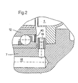
- Fig. 2 shows an enlarged section of a hydrodynamic clutch. From this is u. a. the turbine wheel 4, an angular contact ball bearing 12 with integrated seal 40.
- the workspace is operating equipment in the form of oil through a bore 18 in Drive shaft 7 and supplied through distribution bores 19.
- the seal 40 are not wetted by oil can.
Description
Die Erfindung betrifft eine hydrodynamische Kupplung, im einzelnen mit den Merkmalen des Oberbegriffs des Anspruchs 1.The invention relates to a hydrodynamic coupling, in particular with the Features of the preamble of claim 1.
Hydrodynamische Kupplungen sind für eine Vielzahl von Anwendungsfällen in einer Vielzahl von Ausführungen bekannt. Ein Anwendungsfall einer hydrodynamischen Kupplung in einem Turbocompoundsystem ist in der Druckschrift DE 92 02 578.1 offenbart. Diese Kupplung ist an den Schmierölkreislauf der Verbrennungskraftmaschine angeschlossen und nutzt dessen Öl als Arbeits- und als Kühlmittel.Hydrodynamic couplings are used in a variety of applications a variety of designs known. A use case one hydrodynamic coupling in a turbo compound system is in the Publication DE 92 02 578.1 discloses. This clutch is on the Lubricating oil circuit of the internal combustion engine connected and used its oil as a working and cooling agent.
DE 198 02 524 beschreibt eine hydrodynamische Kupplung, bei welcher der aus Rotor und Stator gebildete Arbeitsraum direkt über die Abtriebswelle mit Öl versorgt ist. Das Öl gelangt dabei durch eine Bohrung in der Abtriebswelle sowie über radiale Verteilbohrungen in den Arbeitsraum. Das Pumpenrad ist hierbei auf der Abtriebswelle mittels Wälzlagern gelagert. Ein Teil des Ölstromes, der zum Arbeitsraum geführt wird, wird abgezweigt und den Lagern zur Schmierung zugeführt. Die Abstützung erfolgt dabei vorzugsweise über eine Lageranordnung, umfassend wenigstens ein Lager, vorzugsweise zwei Lager, wobei vorzugsweise aufgrund der guten Aufnahmefähigkeit für kombinierte Belastungen Schrägkugellager verwendet werden. Die Schrägkugellager werden dabei paarweise nebeneinander angeordnet. Die Anordnung dieser Lagerung erfolgt dabei in radialer Richtung unterhalb des vom Pumpenrad beschriebenen Arbeitsraumteiles. In axialer Richtung in Einbaulage betrachtet erfolgt die Anordnung der Lagerung vorzugsweise im Bereich der Trennebene, welche von der Beschaufelung von Pumpenrad und Turbinenrad gebildet wird. Zur Betriebsmittelversorgung ist eine sich durch die Abtriebswelle erstreckende Zentralbohrung vorgesehen, von welcher sich in radialer Richtung in Umfangsrichtung der Abtriebswelle Verteilkanäle erstrecken. Diese sind in Einbaulage der Kupplung derart angeordnet, daß diese ebenfalls im Bereich der Trennebene zwischen Turbinen- und Pumpenrad liegen. Die Verteilkanäle münden in einen von Pumpen- und Turbinenrad in Einbaulage beschriebenen und dem torusförmigen Arbeitsraum vorgelagerten Zufuhrraum. Dieser wird in axialer Richtung vom Turbinenrad sowie auf seiten des Pumpenrades im wesentlichen von der Lageranordnung begrenzt. Zur Realisierung einer Teilstromabzweigung für die Lageranordnung sind entsprechende Mittel im Betriebsmittelzufuhrraum vorgesehen. Diese können beispielsweise in Form einer Scheibe mit im Querschnitt abgeschrägter Innenkontur ausgeführt sein. Der dadurch entstehende Durchlaß dient der Dosierung des Schmiermittelflusses durch die Lager.DE 198 02 524 describes a hydrodynamic coupling in which the Working space formed from rotor and stator directly via the output shaft Oil is supplied. The oil gets through a hole in the output shaft as well as radial distribution bores in the work area. The impeller is mounted on the output shaft by means of roller bearings. Part of the Oil flow that is led to the work area is branched off and the Bearings fed for lubrication. The support is preferably carried out via a bearing arrangement, comprising at least one bearing, preferably two bearings, preferably due to the good capacity for combined loads angular contact ball bearings can be used. The Angular contact ball bearings are arranged side by side in pairs. The This storage is arranged in the radial direction below the Workspace part described by the impeller. In the axial direction in Considering the installation position, the arrangement of the storage is preferably in Area of the parting plane, which depends on the blading of the impeller and Turbine wheel is formed. One is through for the supply of resources the output shaft extending central bore is provided, from which in the radial direction in the circumferential direction of the output shaft distribution channels extend. In the installed position of the clutch, these are arranged in such a way that this also in the area of the parting plane between turbine and Pump wheel lie. The distribution channels open into one of pump and Turbine wheel described in the installation position and the toroidal Working space upstream feed space. This is in the axial direction from Turbine wheel and on the side of the pump wheel essentially from the Bearing arrangement limited. To implement a partial flow branch for the Bearing arrangements are corresponding means in the equipment supply space intended. These can, for example, in the form of a disc with Cross-section bevelled inner contour. The result The resulting passage serves to meter the lubricant flow through the Camp.
Die Kupplung ist dabei an den Schmierölkreislauf eines Verbrennungsmotors angeschlossen. Das Öl des Verbrennungsmotors wird dabei gleichzeitig in der Kupplung als Arbeitsmittel sowie als Kühlmittel ausgenutzt.The clutch is connected to the lubricating oil circuit of an internal combustion engine connected. The oil of the internal combustion engine is simultaneously in the clutch used as a working fluid and as a coolant.
Die genannten Lager sind für die Lebensdauer der gesamten Kupplung entscheidend. Es ist daher auf deren ausreichende Dimensionierung sowie auf den richtigen Einbau zu achten, insbesondere auch auf die Wartung und auf die ausreichende Schmierung. Die Lebensdauer der Lager selbst hat bisher jedoch nicht befriedigt. Es kommt immer wieder zu Ausfällen. Man versuchte, das Problem durch Verwendung größerer Lager zu begegnen, jedoch ohne Erfolg.The bearings mentioned are for the life of the entire coupling crucial. It is therefore due to their adequate sizing as well to pay attention to the correct installation, in particular also to the maintenance and for sufficient lubrication. The life of the bearing itself has not yet satisfied. There are always failures. you tried to counter the problem by using larger bearings but without success.
US 5,778,668, zeigt eine hydrodynamische Kupplung mit den Merkmalen des Oberbegriffs von Anspruch 1.US 5,778,668 shows a hydrodynamic coupling with the features of The preamble of claim 1.
DE 30 02 804 A1 beschreibt eine hydrodynamische Kupplung für den Antrieb von Bändern, welche unter Tage eingesetzt wird. Diese hydrodynamische Kupplung verwendet als Arbeitsmedium wasser, so dass spezielle abgedichtete, fettgeschmierte Lager verwendet werden müssen.DE 30 02 804 A1 describes a hydrodynamic coupling for driving Bands that are used underground. This hydrodynamic clutch uses water as the working medium, so special sealed, grease-lubricated Bearings must be used.
Der Erfindung liegt die Aufgabe zugrunde, eine hydrodynamische Kupplung der genannten Art, insbesondere für den Einatz in Fahrzeugen, derart zu gestalten, daß die Lebensdauer der Lager entscheidend verbessert wird. Eine einfache konstruktive Ausführung mit geringer Bauteilanzahl und geringem Bauraumbedarf sind beizubehalten.The invention has for its object a hydrodynamic coupling of the type mentioned, in particular for use in vehicles shape that the life of the bearings is significantly improved. A simple structural design with a small number of components and low Space requirements must be maintained.
Diese Aufgabe wird durch die Merkmale von Anspruch 1 gelöst. This object is solved by the features of claim 1.
Die Erfinder haben erkannt, daß die geringe Viskosität des Öls die Ursache des Übels ist, aber auch Ablagerungen, die im Öl enthalten sind. Dies kann während des Betriebes schon sehr bald zu Lagerschäden führen.The inventors have recognized that the low viscosity of the oil is the cause of the evil, but also deposits that are contained in the oil. This can very soon lead to bearing damage during operation.
Sie haben daraufhin die entsprechenden Maßnahmen getroffen. Sie sind nämlich von der an sich sehr praktischen Schmierung mittels des Öles, das als Arbeitsmedium dient, abgegangen und zu einer Fettschmierung übergegangen. Sie haben außerdem die Lager in zuverlässiger Weise abgedichtet, so daß es gegen Eindringen von Öl und damit gegen Ablagerungen geschützt ist. Durch diese verhältnismäßig einfachen Maßnahmen konnte die Lebensdauer gegenüber vorbekannten Turbokupplungen um ein Mehrfaches gesteigert werden.You then took the appropriate measures. they are namely from the very practical lubrication by means of the oil that serves as a working medium, gone and for grease lubrication passed. They also have the bearings in a reliable manner sealed so that it is against oil ingress and thus against Deposits is protected. Through this relatively simple Measures could be taken against the known lifespan Turbo couplings can be increased several times.
Die erfindungsgemäße Lösung ist sowohl für den Einsatz in Fahrzeugen als auch in stationären Anlagen einsetzbar.The solution according to the invention is both for use in vehicles and can also be used in stationary systems.
Die Erfindung ist anhand der Zeichnung näher erläutert. Darin ist eine hydrodynamische Kupplung dargestellt, die im sogenannten Turbocompoundsystem betrieben wird, wobei das Arbeitsmedium der Kupplung gleichzeitig als Schmieröl eines zugeordneten Verbrennungsmotors dient, gegebenenfalls auch eines zugeordneten Getriebes.The invention is explained in more detail with reference to the drawing. There is one in it hydrodynamic coupling shown in the so-called Turbocompoundsystem is operated, the working medium Coupling simultaneously as a lubricating oil of an assigned internal combustion engine serves, possibly also an associated gear.
Die hydrodynamische Kupplung 1 umfaßt ein Primärrad 3, welches auch als
Pumpenrad bezeichnet wird und ein Sekundärrad 4, welches als Turbinenrad
bezeichnet ist. Pumpen- und Turbinenrad 3 bzw. 4 bilden miteinander
wenigstens einen torusförmigen Arbeitsraum 5, welcher mit einem
Betriebsfluid, das Schmieröl ist befüllbar ist. Das Pumpenrad 3 wird von
einem Zahnrad angetrieben. Dieses sitzt auf einer hier nicht dargestellten
Welle. Zu diesem Zweck kämmt das Zahnrad mit einem drehfest mit dem
Pumpenrad 3 gekoppelten Zahnrad 6. The hydrodynamic clutch 1 comprises a
Das Turbinenrad 4 ist auf einer Abtriebswelle 7 der hydrodynamischen
Kupplung 1 angeordnet. Im dargestellten Ausführungsbeispiel ist das
Turbinenrad 4 mit der Abtriebswelle 7 drehfest mittels kraft- bzw.
formschlüssiger Verbindungen in Form von Schraubverbindungen, hier
stellvertretend die Schraubverbindungen 8 und 9, gekoppelt.The
Das Pumpenrad 3 ist über eine Lageranordnung 10, welche vorzugsweise
zwei Kugellager 11 und 12 umfaßt, wenigstens mittelbar auf der
Abtriebswelle 7 gelagert. Die Kugellager der Lageranordnung 10 sind als
Schrägkugellager ausgeführt. Diese ermöglichen es, kombinierte Belastungen,
d. h. Radial- und Axialkräfte besser als Rillenkugellager aufzunehmen. Das
Pumpenrad 3 stützt sich über die Außenringe 13 bzw. 14 der
Schrägkugellager 11 bzw. 12 und der Innenringe 15 bzw. 16 direkt auf der
Abtriebswelle 7 ab. Die Anordnung dieser Lagerung erfolgt dabei in radialer
Richtung unterhalb des vom Pumpenrad beschriebenen Arbeitsraumteiles. In
axialer Richtung in Einbaulage betrachtet erfolgt die Anordnung der Lagerung
vorzugsweise im Bereich der Trennebene, welche von der Beschaufelung von
Pumenrad und Turbinenrad gebildet wird. Das Pumpenrad ist somit fliegend
gelagert. Zur Realisierung der Drehmomentenaufnahme am Pumpenrad und
Weitergabe über das Arbeitsöl an das Turbinenrad 4 erfolgen die Rotation von
Pumpenrad 3 und den Außenringen 13 bzw. 14 der Schrägkugellager 11 bzw.
12 mit gleicher Drehzahl. Zwischen den Außenringen 13 bzw. 14 sowie dem
Pumpenrad 3 sind zu diesem Zweck Preßsitze vorgesehen. Analoges gilt für
die Abstützung des Zahnrades 6 über eine weitere Lageranordnung 17 auf
der Abtriebswelle 7. Ganz wichtig ist die Dichtung 40, die in die
Lageranordnung 10 integriert ist, und die die Lageranordnung nach außen hin
abdichtet.The
Die Ölversorgung des Arbeitsraumes 5 erfolgt im dargestellten Fall direkt über
die Abtriebswelle 7. Zu diesem Zweck weist die Abtriebswelle 7 eine
Bohrung 18 auf, die vorzugsweise koaxial zur Symmetrieachse A der
Abtriebswelle 7 angeordnet ist. Diese Bohrung erstreckt sich von der
Primärseite bis in etwa zur durch die Mittelsenkrechte durch den
torusförmigen Arbeitsraum gelegten Ebene E. Von dieser Zentralbohrung 18
gehen weitere Verteilbohrungen 19 bzw. 20 ab, welche sich von der
Zentralbohrung 18 bis an den Außenumfang 21 der Abtriebswelle 7 in radialer
Richtung erstrecken. Über die Zentralbohrung 18 und die Verteilbohrungen 19
und 20 wird das Betriebsfluid in den torusförmigen Arbeitsraum 5 geleitet.The oil supply to the working space 5 takes place directly in the case shown
the
Gemäß der Erfindung ist die Lageranordnung gegen den Eintritt von Arbeitsöl abgedichtet, d.h. die Betriebsmittelzufuhr erfolgt an der Abdichtung vorbei. Außerdem ist der Lager-Innenraum mit Fett gefüllt, das einen hochviskosen Schmierstoff enthält, und das besonders für relativ niedrige Drehzahlen geeignet ist.According to the invention, the bearing arrangement is against the entry of working oil sealed, i.e. the equipment is supplied past the seal. In addition, the interior of the warehouse is filled with grease, which makes it highly viscous Contains lubricant, especially for relatively low speeds suitable is.
Die hydrodynamische Kupplung 1 wird von einem glockenförmigen
Gehäuse 26 umschlossen. Dieses vorzugsweise als Tiefziehteil ausgeführt
und mittels verschiedener Verbindungsmöglichkeiten vorzugsweise
wenigstens mittelbar mit dem Zahnrad befestigt. Es besteht jedoch auch die
theoretische, jedoch hier nicht im einzelnen dargestellte Möglichkeit, das
Gehäuse entweder drehfest mit dem Pumpenrad 3 oder dem Turbinenrad 4
zu koppeln, wobei jedoch immer zwischen dem Pumpenrad 3 und dem
Gehäuse 26 ein Zwischenraum 27 gebildet wird. Aufgrund der Kopplung
zwischen Gehäuse 26 und Zahnrad 6 läuft ersteres im Betrieb der Kupplung
bzw. beim Antrieb des Pumpenrades 3 mit um.The hydrodynamic clutch 1 is of a bell-shaped
Während des Betriebes der Kupplung gelangt Arbeitsöl aus dem
torusförmigen Arbeitsraum 5 in die Zwischenräume 27. Das Arbeitsöl ist damit
nicht mehr der kreisförmigen und spülenden Strömung zwischen der
Beschaufelung der beiden Schaufelräder, Pumpenrad und Turbinenrad,
ausgesetzt sondern dann nur noch der durch die Rotation der Kupplung
erzeugten Fliehkraft. Verunreinigungen im Arbeitsöl werden dann aufgrund
ihres spezifisch höheren Gewichtes gegen die Innenwand 30 des
Gehäuses 26 geschleudert, wo eine Ablagerungsgefahr zumindest immer
dann besteht, wenn an dieser Innenseite 30 Unebenheiten in Form von
Vorsprüngen, Vertiefungen oder Kanten vorgesehen sind bzw. diese eine
ungenügende Oberflächengüte aufweist. Dies kann zum Berühren des
Sekundärrades 4 mit dem Gehäuse 26 führen, wodurch sich eine starre
Kopplung zwischen Primär- und Sekundärseite ergeben kann. Des weiteren
können örtliche Ablagerungen an umlaufenden Gehäusen die Ausbildung von
Unwuchten bedingen, welche in Biegeschwingungen resultieren. Zur Lösung
. dieses Problemes sind im Pumpenrad 3 Öffnungen 31, beispielsweise in Form
eines Verbindungskanales zwischen Schaufelgrund und Außenumfang des
Schaufelrades, der derart ausgerichtet ist, daß dessen Lage sich wenigstens
mit einer Richtungskomponente in Strömungsrichtung im Betriebszustand
zwischen Pumpen- und Turbinenrad sowie im wesentlichen tangential zur
Kontur des sich zwischen Pumpen- und Turbinenschaufelrad einstellenden
Strömungsverlaufes beschreiben läßt, vorgesehen, welche die Bildung eines
Nebenstromes vom Arbeitsraum 5 zum Zwischenraum 27 ermöglichen. Die
Öffnungen 31 erstrecken sich dabei vorzugsweise von der Innenfläche des
beschaufelten Teiles, insbesondere vom Schaufelgrund 32 zum
Außenumfang 33 des Pumpenrades 3. Die Öffnungen 31 sind dabei derart
ausgerichtet, daß wenigstens eine Richtungskomponente zur Beschreibung
der Lage vorhanden ist, die im wesentlichen tangential zur Kontur des
Arbeitsölkreislaufes im torusförmigen Arbeitsraum 5 im Betriebszustand
betrachtet ausgerichtet ist. Die Richtung der tangentialen Komponente,
welche zur Beschreibung der Ausrichtung der Öffnung 31 herangezogen
werden kann, ist dabei immer in Richtung der Strömung im Kreislauf im
torusförmigen Arbeitsraum 5 ausgerichtet.When the clutch is operating, working oil escapes from the
toroidal working space 5 in the
Vorzugsweise sind eine Vielzahl von Öffnungen in Umfangsrichtung der
hydrodynamischen Kupplung, insbesondere des Pumpenrades 3,
vorgesehen, wobei diese vorzugsweise in gleicher Höhe und auf einer
theoretisch gedachten Umfangslinie UL am Umfang 33 des Pumpenrades 3
angeordnet sind. Die Abstände zwischen den einzelnen Öfffnungen 31 sind
vorzugsweise konstant gewählt.A plurality of openings are preferably provided in the circumferential direction of the hydrodynamic coupling, in particular of the
Die Öffnung 31 weist im dargestellten Fall vom Schaufelgrund bis zum
Außenumfang 33 des Pumpenrades 3 einen konstanten Querschnitt auf und
ist in Form einer Durchgangsbohrung ausgeführt. Jeder andere mögliche
Querschnitt ist ebenfalls denkbar. Des weiteren besteht die hier im einzelnen
nicht dargestellte Möglichkeit, die Öffnung 31 über ihre Erstreckung von der
Schaufelradinnenfläche 31 des Pumpenrades 3 bis zum Außenumfang des
Pumpenrades 3 mit unterschiedlichen Querschnitten zur Beeinflussung des
darüber fließenden Nebenstromes zu versehen.The
Fig. 2 zeigt in vergrößerter Darstellung einen Ausschnitt aus einer
hydrodynamischen Kupplung. Von dieser ist wiederum u. a. das Turbinenrad
4 zu sehen, ferner ein Schrägkugellager 12 mit integrierter Dichtung 40.Fig. 2 shows an enlarged section of a
hydrodynamic clutch. From this is u. a. the
Dem Arbeitsraum wird Betriebsmittel in Form von Öl durch eine Bohrung 18 in
Antriebswelle 7 sowie durch Verteilbohrungen 19 zugeführt. Dabei ist die
Anordnung derart getroffen, daß die Dichtung 40 nicht von Öl benetzt werden
kann.The workspace is operating equipment in the form of oil through a
Claims (9)
- A hydrodynamic coupling (1);with the operating medium supply system comprising:1.1 with a pump impeller (3) and a turbine impeller (4) which jointly form at least one toroidal working chamber (5) which can be filled with an operating medium from an operating medium supply system, with the operating medium being tube oil;1.2 with a housing (26) enclosing the pump impeller (3) in the axial direction at least partly;1.3 with the housing (26) forming at least an intermediate cavity (27) with pump impeller (3);1.4 with the pump impeller (3) being held by way of a bearing arrangement (10) at least indirectly on the driven shaft (7);characterized by the following features:1.5 an operating medium supply chamber which is arranged radially below the toroidal working chamber (5);1.5.2 a central operating medium supply conduit which is arranged in the drive shaft (7);1.5.3 at least one distribution conduit (19, 20) which connects the central operating medium supply channel (18) with the operating medium supply chamber;1.6 the bearing arrangement (10) comprises lubricating grease;1.7 the bearing arrangement (10) is sealed towards the outside.
- A hydrodynamic coupling (1) as claimed in claim 1, characterized in that the operating medium of the coupling acts simultaneously as the tube oil of an internal combustion engine associated with the hydrodynamic coupling.
- A hydrodynamic coupling as claimed in one of the claims 1 to 2, characterized in that the housing (26) revolves in the operating state of the coupling (1).
- A hydrodynamic coupling as claimed in claim 1 to 3, characterized by such a guidance of the operating medium from and to the working chamber (5) that the sealing of the bearing arrangement (10), especially a sealing lip belonging thereto, is not wetted by the operating medium.
- A hydrodynamic coupling as claimed in claim 3 or 4, characterized in that the housing (26) is coupled at least indirectly with the pump impeller (3).
- A hydrodynamic coupling as claimed in claim 3, characterized in that the housing (26) is coupled at least indirectly with the turbine impeller (4).
- A hydrodynamic coupling as claimed in one of the claims 1 to 6, characterized in that the connecting conduit between the toroidal working chamber (5) and the intermediate cavity (27) is aligned tangentially in the direction to the circulation contour of the flow circulation obtained in the operating state between the pump impeller (3) and the turbine impeller (4).
- A hydrodynamic coupling as claimed in one of the claims 1 to 7, characterized in that the connecting conduit (31) has a straight progress which is free from any changes in direction.
- A hydrodynamic coupling as claimed in one of the claims 1 to 8, characterized in that the bearing arrangement (10) occurs below the working chamber section describable by the pump impeller (3).
Applications Claiming Priority (2)
| Application Number | Priority Date | Filing Date | Title |
|---|---|---|---|
| DE19848541 | 1998-10-21 | ||
| DE19848541 | 1998-10-21 |
Publications (3)
| Publication Number | Publication Date |
|---|---|
| EP0995918A2 EP0995918A2 (en) | 2000-04-26 |
| EP0995918A3 EP0995918A3 (en) | 2002-02-27 |
| EP0995918B1 true EP0995918B1 (en) | 2004-09-15 |
Family
ID=7885201
Family Applications (1)
| Application Number | Title | Priority Date | Filing Date |
|---|---|---|---|
| EP99120774A Expired - Lifetime EP0995918B1 (en) | 1998-10-21 | 1999-10-20 | Hydrodynamic clutch |
Country Status (2)
| Country | Link |
|---|---|
| EP (1) | EP0995918B1 (en) |
| DE (1) | DE59910503D1 (en) |
Families Citing this family (4)
| Publication number | Priority date | Publication date | Assignee | Title |
|---|---|---|---|---|
| DE10360056A1 (en) | 2003-12-22 | 2005-07-21 | Voith Turbo Gmbh & Co. Kg | Hydrodynamic coupling |
| DE102004064226B3 (en) | 2004-03-08 | 2020-01-23 | Voith Turbo Gmbh & Co. Kg | Turbo compound unit |
| DE102013214079A1 (en) * | 2013-07-18 | 2015-01-22 | Voith Patent Gmbh | Hydrodynamic machine |
| CN111677834A (en) * | 2020-06-03 | 2020-09-18 | 韩石全 | Hydraulic coupler mirror rotor and processing method thereof |
Family Cites Families (6)
| Publication number | Priority date | Publication date | Assignee | Title |
|---|---|---|---|---|
| GB1151216A (en) * | 1965-08-16 | 1969-05-07 | Fluidrive Eng Co Ltd | Hydraulic Turbo Couplings |
| DE3002804A1 (en) * | 1980-01-26 | 1981-07-30 | K. Schumacher GmbH & Co KG, 4300 Essen | Hydromechanical coupling for mining machinery - has permanently greased bearings and has corrosion protection on exposed shaft portion between inner bearing seals |
| DE8613508U1 (en) * | 1986-05-17 | 1986-07-10 | Voith Turbo Gmbh & Co Kg, 7180 Crailsheim | Sealing arrangement |
| DE19522753C2 (en) * | 1995-06-26 | 1999-08-12 | Voith Turbo Kg | Arrangement of a hydrodynamic clutch in a drive system |
| DE19802524B4 (en) * | 1998-01-26 | 2005-12-22 | Voith Turbo Gmbh & Co. Kg | Hydrodynamic coupling |
| DE19809598A1 (en) * | 1998-03-06 | 1999-09-23 | Voith Turbo Kg | Hydrodynamic coupling for wind turbines |
-
1999
- 1999-10-20 EP EP99120774A patent/EP0995918B1/en not_active Expired - Lifetime
- 1999-10-20 DE DE59910503T patent/DE59910503D1/en not_active Expired - Lifetime
Also Published As
| Publication number | Publication date |
|---|---|
| DE59910503D1 (en) | 2004-10-21 |
| EP0995918A3 (en) | 2002-02-27 |
| EP0995918A2 (en) | 2000-04-26 |
Similar Documents
| Publication | Publication Date | Title |
|---|---|---|
| DE60216474T2 (en) | TOUCH-FREE SEAL FOR LARGE AXLE SPRING APPLICATIONS | |
| EP3029357A1 (en) | Device with a stationary first component and a second component which can be rotated and connected at least partially with the first component | |
| EP1544504A2 (en) | Planetary transmission, in particular for wind power plant | |
| DE60128631T2 (en) | water pump | |
| EP0268904B1 (en) | Transmission with means for lubricating oil supply | |
| DE10256086A1 (en) | Ball bearings and a vacuum pump equipped with this type of bearing | |
| DE4200687A1 (en) | Radial bearing with bearing bush and lubrication gap - has tangential oil supply bores in bearing housing opening into oil chamber | |
| DE2138152A1 (en) | TURBOMOLECULAR VACUUM PUMP | |
| EP1327802A2 (en) | Hydraulic sealing arrangement | |
| EP0995918B1 (en) | Hydrodynamic clutch | |
| EP0751027B1 (en) | Disposition of a hydrodynamic clutch within a drive system | |
| DE3005728A1 (en) | CLUTCH | |
| EP1319871B1 (en) | Supplying lubricant for a planetary transmission | |
| DE2209345A1 (en) | Storage device | |
| DE3708054C2 (en) | ||
| EP1254330B1 (en) | Device for sealing a space | |
| EP3650689A1 (en) | Output module with integrated bearing ring | |
| EP1233211B1 (en) | Differential gearing with lubricating device | |
| EP1049882B1 (en) | Hydrodynamic coupling | |
| EP0188713B1 (en) | Oil feeding device for vacuum pumps | |
| DE102017106942A1 (en) | Hydrodynamic coupling | |
| DE102017206686A1 (en) | Bearing arrangement for mounting a transmission shaft | |
| DE102016222455A1 (en) | Planetary gear, in particular Stirnraddifferentialgetriebe or reduction precursor this | |
| DE2800047A1 (en) | FLOW MACHINE | |
| DE2542947C3 (en) | Solid lubricating ring designed as a hollow ring to supply a plain bearing with lubricant |
Legal Events
| Date | Code | Title | Description |
|---|---|---|---|
| PUAI | Public reference made under article 153(3) epc to a published international application that has entered the european phase |
Free format text: ORIGINAL CODE: 0009012 |
|
| AK | Designated contracting states |
Kind code of ref document: A2 Designated state(s): AT BE CH CY DE DK ES FI FR GB GR IE IT LI LU MC NL PT SE Kind code of ref document: A2 Designated state(s): DE FR GB IT SE |
|
| AX | Request for extension of the european patent |
Free format text: AL;LT;LV;MK;RO;SI |
|
| 17P | Request for examination filed |
Effective date: 20011001 |
|
| PUAL | Search report despatched |
Free format text: ORIGINAL CODE: 0009013 |
|
| AK | Designated contracting states |
Kind code of ref document: A3 Designated state(s): AT BE CH CY DE DK ES FI FR GB GR IE IT LI LU MC NL PT SE |
|
| AX | Request for extension of the european patent |
Free format text: AL;LT;LV;MK;RO;SI |
|
| AKX | Designation fees paid |
Free format text: DE FR GB IT SE |
|
| 17Q | First examination report despatched |
Effective date: 20031106 |
|
| GRAP | Despatch of communication of intention to grant a patent |
Free format text: ORIGINAL CODE: EPIDOSNIGR1 |
|
| GRAS | Grant fee paid |
Free format text: ORIGINAL CODE: EPIDOSNIGR3 |
|
| GRAA | (expected) grant |
Free format text: ORIGINAL CODE: 0009210 |
|
| AK | Designated contracting states |
Kind code of ref document: B1 Designated state(s): DE FR GB IT SE |
|
| REG | Reference to a national code |
Ref country code: GB Ref legal event code: FG4D Free format text: NOT ENGLISH |
|
| REG | Reference to a national code |
Ref country code: IE Ref legal event code: FG4D Free format text: GERMAN |
|
| REF | Corresponds to: |
Ref document number: 59910503 Country of ref document: DE Date of ref document: 20041021 Kind code of ref document: P |
|
| GBT | Gb: translation of ep patent filed (gb section 77(6)(a)/1977) |
Effective date: 20041109 |
|
| REG | Reference to a national code |
Ref country code: SE Ref legal event code: TRGR |
|
| REG | Reference to a national code |
Ref country code: IE Ref legal event code: FD4D |
|
| PLBE | No opposition filed within time limit |
Free format text: ORIGINAL CODE: 0009261 |
|
| STAA | Information on the status of an ep patent application or granted ep patent |
Free format text: STATUS: NO OPPOSITION FILED WITHIN TIME LIMIT |
|
| ET | Fr: translation filed | ||
| 26N | No opposition filed |
Effective date: 20050616 |
|
| PGFP | Annual fee paid to national office [announced via postgrant information from national office to epo] |
Ref country code: GB Payment date: 20131029 Year of fee payment: 15 |
|
| PGFP | Annual fee paid to national office [announced via postgrant information from national office to epo] |
Ref country code: SE Payment date: 20141021 Year of fee payment: 16 Ref country code: FR Payment date: 20141022 Year of fee payment: 16 |
|
| PGFP | Annual fee paid to national office [announced via postgrant information from national office to epo] |
Ref country code: IT Payment date: 20141030 Year of fee payment: 16 |
|
| GBPC | Gb: european patent ceased through non-payment of renewal fee |
Effective date: 20141020 |
|
| PG25 | Lapsed in a contracting state [announced via postgrant information from national office to epo] |
Ref country code: GB Free format text: LAPSE BECAUSE OF NON-PAYMENT OF DUE FEES Effective date: 20141020 |
|
| REG | Reference to a national code |
Ref country code: SE Ref legal event code: EUG |
|
| PG25 | Lapsed in a contracting state [announced via postgrant information from national office to epo] |
Ref country code: IT Free format text: LAPSE BECAUSE OF NON-PAYMENT OF DUE FEES Effective date: 20151020 |
|
| REG | Reference to a national code |
Ref country code: FR Ref legal event code: ST Effective date: 20160630 |
|
| PG25 | Lapsed in a contracting state [announced via postgrant information from national office to epo] |
Ref country code: FR Free format text: LAPSE BECAUSE OF NON-PAYMENT OF DUE FEES Effective date: 20151102 Ref country code: SE Free format text: LAPSE BECAUSE OF NON-PAYMENT OF DUE FEES Effective date: 20151021 |
|
| PGFP | Annual fee paid to national office [announced via postgrant information from national office to epo] |
Ref country code: DE Payment date: 20161020 Year of fee payment: 18 |
|
| REG | Reference to a national code |
Ref country code: DE Ref legal event code: R119 Ref document number: 59910503 Country of ref document: DE |
|
| PG25 | Lapsed in a contracting state [announced via postgrant information from national office to epo] |
Ref country code: DE Free format text: LAPSE BECAUSE OF NON-PAYMENT OF DUE FEES Effective date: 20180501 |