EP0995675A2 - Verfahren zur Verminderung des Wellenwiderstandes eines Flugzeuges - Google Patents
Verfahren zur Verminderung des Wellenwiderstandes eines Flugzeuges Download PDFInfo
- Publication number
- EP0995675A2 EP0995675A2 EP99104595A EP99104595A EP0995675A2 EP 0995675 A2 EP0995675 A2 EP 0995675A2 EP 99104595 A EP99104595 A EP 99104595A EP 99104595 A EP99104595 A EP 99104595A EP 0995675 A2 EP0995675 A2 EP 0995675A2
- Authority
- EP
- European Patent Office
- Prior art keywords
- main wing
- wing
- engine nacelle
- airplane
- wave resistance
- Prior art date
- Legal status (The legal status is an assumption and is not a legal conclusion. Google has not performed a legal analysis and makes no representation as to the accuracy of the status listed.)
- Granted
Links
Images


Classifications
-
- B—PERFORMING OPERATIONS; TRANSPORTING
- B64—AIRCRAFT; AVIATION; COSMONAUTICS
- B64D—EQUIPMENT FOR FITTING IN OR TO AIRCRAFT; FLIGHT SUITS; PARACHUTES; ARRANGEMENTS OR MOUNTING OF POWER PLANTS OR PROPULSION TRANSMISSIONS IN AIRCRAFT
- B64D29/00—Power-plant nacelles, fairings, or cowlings
- B64D29/02—Power-plant nacelles, fairings, or cowlings associated with wings
-
- B—PERFORMING OPERATIONS; TRANSPORTING
- B64—AIRCRAFT; AVIATION; COSMONAUTICS
- B64D—EQUIPMENT FOR FITTING IN OR TO AIRCRAFT; FLIGHT SUITS; PARACHUTES; ARRANGEMENTS OR MOUNTING OF POWER PLANTS OR PROPULSION TRANSMISSIONS IN AIRCRAFT
- B64D27/00—Arrangement or mounting of power plant in aircraft; Aircraft characterised thereby
- B64D27/02—Aircraft characterised by the type or position of power plant
- B64D27/16—Aircraft characterised by the type or position of power plant of jet type
- B64D27/18—Aircraft characterised by the type or position of power plant of jet type within or attached to wing
-
- Y—GENERAL TAGGING OF NEW TECHNOLOGICAL DEVELOPMENTS; GENERAL TAGGING OF CROSS-SECTIONAL TECHNOLOGIES SPANNING OVER SEVERAL SECTIONS OF THE IPC; TECHNICAL SUBJECTS COVERED BY FORMER USPC CROSS-REFERENCE ART COLLECTIONS [XRACs] AND DIGESTS
- Y02—TECHNOLOGIES OR APPLICATIONS FOR MITIGATION OR ADAPTATION AGAINST CLIMATE CHANGE
- Y02T—CLIMATE CHANGE MITIGATION TECHNOLOGIES RELATED TO TRANSPORTATION
- Y02T50/00—Aeronautics or air transport
- Y02T50/40—Weight reduction
Definitions
- the present invention relates to a method for reducing the wave resistance in an airplane by retarding the generation of a shock wave on an upper surface of a main wing of the airplane when the airplane is cruising at a transonic speed.
- a shock wave is generated in a range of transonic speed locally exceeding sonic speed by the flow accelerated at a portion of an airframe (see Fig. 20). If the shock wave is generated in this manner on the upper surface of the main wing, the flow speed of the air flow is suddenly decreased from a supersonic speed to a subsonic speed across the shock wave. As a result, a boundary layer is peeled off at a location downstream of the shock wave to generate a following wake which provides a large wave resistance and hence, the main wing is brought into a so-called shock stalling state due to the sudden increase in drag and the sudden decrease in lift force.
- the phenomenon of a sudden increase in drag due to the generation of the shock wave is called a drag emanation, and the mach number of a main flow at that time, is called a drag emanating mach number M DD .
- the drag emanating mach number M DD When the flying speed of the airplane reaches the drag emanating mach number M DD , not only is the amount of fuel consumed increased due to the increase in drag, but also the balance of an airframe of the airplane is adversely influenced by the movement of the center of wind pressure. For this reason, it is necessary to retard the generation of the shock wave as much as possible to increase the drag emanating mach number M DD .
- the reduction of interference drag is generally provided by mounting engine nacelles to laterally opposite sides of a rear portion of the fuselage having a small interference with a main wing in a business jet plane, and by mounting engine nacelles through pylons to a lower surface of the main wing along which air flows at a lower speed as compared with air flow along an upper surface of the main wing in a large-sized passenger airplane.
- the drag emanating mach number M DD is higher, but if the thickness is decreased, the volume of the main wing is decreased. For this reason, when a fuel tank is provided within the main wing, there is a problem that the amount of fuel carried therein is decreased, and moreover, there is a problem that a structure weight is increased, because a reduction in strength due to the decrease in thickness is compensated. Therefore, a peaky wing and a supercritical wing have been proposed as a wing profile which inhibits the generation of a shock wave, while ensuring a required thickness by improving the pressure profile on the main wing in the range of transonic speed.
- the drag emanating mach number M DD can be increased, while ensuring the wing thickness to a certain extent, but the following problems are encountered: the stalling characteristic at a lower speed is degraded; the structure weight is increased for opposing a larger flexure moment applied to the root of the main wing; and it is difficult to employ a wing of a laminar flow type having a small friction resistance.
- U.S. Patent No. 4,311,289 describes the prevention of the generation of a shock wave by providing a channel defined by a rear edge of a main wing, a fuselage, an engine nacelle and a pylon.
- the ratio of the sectional area of a channel outlet to the minimum sectional area of the channel is set at 1:1.065 or less.
- U.S. Patent No. 4,449,680 describes the reduction in effect of interference between an engine nacelle and a main wing by providing a critical counter area (a portion of the engine nacelle) and a non-critical counter area (the other portion of the engine nacelle and a pylon portion) from a critical zone of the main wing and a critical surface region of the engine nacelle, and forming the critical counter area into a shape which is along a streamline in the vicinity of such area and forming the non-critical counter area into a shape which is not along a streamline in the vicinity of such area.
- U.S. Patent No. 4,314,681 proposes the reduction of the generation of a shock wave by disposing a fairing having a characteristic curve from a thickness-wise intermediate portion to a rear edge of a pylon.
- U.S. Patent No. 4,171,786 proposes the avoidance of an increase in drag without use of a pylon by disposing an engine nacelle supported on a fuselage through an auxiliary wing above a main wing, and defining the height position of the engine nacelle with respect to an upper surface of the main wing and the longitudinal position of the engine nacelle with respect to a front edge of the main wing.
- U.S. Patent No. 3,727,862 proposes the prevention of the generation of resonance between an engine and a main wing by supporting the engine nacelle on the upper surface of the main wing with an elastomer interposed therebetween.
- a fluid element such as an engine nacelle
- a method for reducing the wave resistance of an airplane which comprises disposing a fluid element within the main flow above a rear portion of the air flow on an upper surface of a main wing of the airplane. This generates a negative pressure on the upper surface of the main wing of the airplane when cruising at a transonic speed, and superposing an air flow accelerated in a narrow space defined between a lower surface of the fluid element and the upper surface of the main wing onto the air flow on the upper surface of the main wing, whereby the pressure gradient on the upper surface of the main wing is made gentle to inhibit the generation of a shock wave.
- a shock wave is generated on the upper surface of the main wing to suddenly increase the wave resistance. If the fluid element is disposed within the main flow above the rear portion of the air flow on the upper surface of the main wing, the air flow accelerated in the narrow space defined between the lower surface of the fluid element and the upper surface of the main wing is superposed onto the air flow on the upper surface of the main wing. Therefore, the pressure gradient on the upper surface of the main wing can be made gentle or smoother to inhibit the generation of a shock wave.
- the generation of a wave resistance in the range of transonic speed can be retarded to increase the drag emanating mach number, thereby increasing the cruising speed, while avoiding an increase in amount of fuel consumed.
- the negative pressure at the time when the air flow on the upper surface of the main wing reaches sonic speed is defined as the critical pressure coefficient; a reference point at which the profile of pressure in the direction of a wing chord on the upper surface of the main wing is changed from a state equal to or larger than the critical pressure coefficient to a state smaller than the critical pressure coefficient, is established on the wing chord; and the front end of the fluid element is disposed to the rear of a position which is in front of the reference point by 5% of a length of the wing chord.
- the front end of the fluid element is disposed to the rear of the position 5% (of the length of the wing chord) in front of the reference point at which the negative pressure on the upper surface of the main wing is smaller than the critical pressure coefficient, i.e., the reference point at which the flow speed of the air flow on the upper surface of the main wing is changed from the state equal to or higher than sonic speed to the state lower than sonic speed, a decelerated region of a main flow generated by the fluid element can be effectively superposed onto the air flow on the upper surface of the main wing to reliably inhibit the generation of the shock wave.
- the profile of pressure produced in the direction of the wing chord on the upper surface of the main wing by the deceleration of the air flow on the upper surface of the main wing is a concave negative pressure profile having two negative pressure peaks at front and rear portions of the wing chord, or a convex negative pressure profile having a single negative pressure peak at a central portion of the wing chord.
- the concave negative pressure profile having the two negative pressure peaks at the front and rear portions of the wing chord is produced.
- a lift force is ensured at the front and rear negative pressure peaks, whereby the lift/drag ratio can be increased, and the amount of fuel consumed can be reduced.
- the longitudinal distance between the front end of the fluid element and the front edge of the main wing is in a range of 68% to 100% of the length of the wing chord.
- the longitudinal distance between the front end of the fluid element and the front edge of the main wing is set in the range of 68% to 100% of the length of the wing chord, a shock wave inhibiting effect can be exhibited.
- the longitudinal distance between the front end of the fluid element and the front edge of the main wing is in a range of 75% to 85% of the length of the wing chord.
- the longitudinal distance between the front end of the fluid element and the front edge of the main wing is set in the range of 75% to 85% of the length of the wing chord, a shock wave inhibiting effect can be further effectively exhibited.
- the vertical distance between the lower surface of the fluid element and the upper surface of the main wing is decreased with an increase in longitudinal distance between the front end of the fluid element and the front edge of the main wing.
- the fluid element is a generally cylindrical engine nacelle covering a gas turbine engine.
- the generally cylindrical engine nacelle covering the gas turbine engine is utilized as the fluid element to exhibit a shock wave inhibiting effect and therefore, it is unnecessary to provide a special fluid element, thereby avoiding an increase in weight.
- the vertical distance between the upper surface of the main wing and a lower surface of the engine nacelle is in the range of 30% to 100% of the outside diameter of the engine nacelle.
- the vertical distance between the upper surface of the main wing and the lower surface of the engine nacelle is set in the range of 30% to 100% of the outside diameter of the engine nacelle, a shock wave inhibiting effect can be maintained even if the longitudinal distance of the fluid element is changed.
- the engine nacelle is supported through a pylon rising from the upper surface of the main wing.
- the engine nacelle is mounted on the upper surface of the main wing through the pylon, a wide space for the cabin can be ensured, as compared with the case where the engine nacelle is mounted on the fuselage. Moreover, the flexure moment applied to the root of the main wing by the lift force can be alleviated by the weight of the engine, to contribute to a reduction in structure weight.
- a movable wing surface is provided on the upper surface of the main wing, so that the movable wing surface can be raised and lowered, whereby the sectional area of the flow path in a space defined between the upper surface of the main wing and the lower surface of the engine nacelle functioning as the fluid element, is decreased to increase the lift force by raising the movable wing surface during taking-off and landing of the airplane.
- the lift force of the main wing can be increased during taking-off and landing of the airplane to reduce the taking-off and landing speeds.
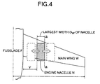
- an airplane in this embodiment is a business jet-propelled airplane having two gas turbine engines, and including a fuselage F, left and right main wings W, W mounted on a lower surface of a central portion of the fuselage F, a vertical tail wing V mounted on a rear portion of the fuselage F, and a horizontal tail wing H mounted at an upper end of the vertical tail wing V.
- Generally cylindrical engine nacelles N, N covering the two gas turbine engines are respectively supported at upper ends of a pair of pylons P, P above the upper surfaces of the left and right main wings W, W.
- the present invention is intended to inhibit the generation a shock wave on the upper surface of the main wing W by positively utilizing the interference of air flow on the upper surface of the main wing W with air flow in the vicinity of the engine nacelle N. Therefore, the position of engine nacelle N mounted relative to an airframe, is an important factor.
- the longitudinal mounting position of the engine nacelle N is based on a front edge of a main-wing chord below the engine nacelle N, and is defined as X/C (%) by a longitudinal distance X from the front edge of the wing chord to a front end (lip) of the engine nacelle N, and a length C of the wing chord. Therefore, when the front end of the engine nacelle N is located above the front edge of the main wing W, X/C is equal to 0%. When the front end of the engine nacelle N is located above a rear edge of the main wing W, X/C is equal to 100%.
- the vertical mounting position of the engine nacelle N is based on the uppermost surface of the main wing W below the engine nacelle N, and is defined as Z/D (%) by a vertical distance Z from the uppermost surface of the main wing W to the lowermost surface of the engine nacelle N, and the largest diameter D of the engine nacelle N.
- the vertical distance Z corresponds to a vertical spacing between the uppermost surface of the main wing W and the lowermost surface of the engine nacelle N in Fig. 3 which is a front view of the airframe.
- the lateral mounting position of the engine nacelle N is based on a laterally outer end of the fuselage F, and is defined as Y/Dw (%) by a lateral distance Y from the laterally outer end of the fuselage F to a laterally inner end of the engine nacelle N, and the largest width Dw of the engine nacelle N.
- the parameter most dominant for inhibiting the generation of a shock wave is X/C.
- the parameter Z/D defining the vertical position of the engine nacelle N has a smaller degree of influence, as compared with such parameter X/C, and the parameter Y/Dw defining the lateral position of the engine nacelle N has a still smaller degree of influence.
- Z/D 0.5 is the vertical position of the engine nacelle N, in which a shock wave inhibiting effect is obtained effectively
- Fig. 7 is a graph showing the coefficient CP of pressure on the upper surface of the main wing corresponding to the wing chord extending along a line a-a in Fig.4, wherein the solid line corresponds to the case where the engine nacelle is not provided; the dashed line corresponds to the case where the engine nacelle position X/C is equal to 75%; and the two-dot dashed line corresponds to the case where the engine nacelle position X/C is equal to 50%.
- the mach number M of the main flow is equal to 0.78, and the lift coefficient CL is equal to 0.40.
- the pressure profile is a concave profile having two negative pressure peaks near the 15% position and near the 85% position on the wing chord.
- the pressure coefficient is remarkably dropped near the 60% position on the chord, in which there is the negative pressure peak when the engine nacelle is not provided.
- the generation of the shock wave and the increase in wave resistance are prevented.
- the pressure coefficient near the 40% position on the wing chord is remarkably dropped, and the pressure profile is a concave profile having two negative pressure peaks near the 10% position and near the 80% position on the wing chord.
- a shock wave is generated near the 80% position on the wing chord due to the presence of the negative pressure peak and the intensive pressure gradient succeeding thereto.
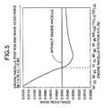
- Fig. 8 is a graph showing the relationship between the mach number M, the drag coefficient resulting from subtraction of the shape drag coefficient CD 0 from the total drag coefficient CD total, and the drag emanating mach number M DD in each of the engine nacelle positions.
- the lift coefficient CL is equal to 0.40.
- a line a corresponds to a reference case where the engine nacelle is not provided (see Fig. 14); lines b , d and e correspond to cases where the engine nacelle is disposed on the upper surface of the main wing (see Fig. 15); lines f and g correspond to cases where the engine nacelle is disposed on the lower surface of the main wing (see Fig. 16); lines h and i correspond to cases where the engine nacelle is disposed at the rear portion of the fuselage (see Fig. 17).
- ⁇ plotted on each of the lines indicates the drag emanating mach number M DD for every engine nacelle position.
- the drag coefficient (CD total - CD 0 ) is highest, and it is presumed that an intensive shock wave has been generated.
- the drag coefficient (CD total - CD 0 ) is lower than that in the case of engine nacelle position X/C equal to 50%, and the effect of inhibiting the generation of the shock wave is observed for the present.
- the effect of inhibiting the generation of the shock wave is not observed in the case of the engine nacelle position X/C equal to -120% (the line f ) nor in the case of the engine nacelle position X/C equal to 80% (the line g ).
- the drag coefficient CD total - CD 0
- the drag coefficient is slightly lower than that in the case indicated by the line g where the engine nacelle is disposed at the rear lower portion of the main wing.
- the line h the case of the engine nacelle position X/C equal to 75%
- the equivalent shock wave inhibiting effect is obtained even if the engine nacelle is mounted on the main wing and on the fuselage.
- the effect of inhibiting the generation of the shock wave is remarkably decreased.
- the drag emanating mach number M DD in which the shock wave is generated on the upper surface of the main wing to suddenly increase the wave resistance, can be varied in an increasing direction, thereby increasing the cruising speed, while suppressing the amount of fuel consumed to a lower level.
- the vertical position Z/D is too large, the influence exerted to an air flow along the upper surface of the main wing by the engine nacelle is reduced and hence, the effect is close to that in the case where the engine nacelle is not provided.
- the position of a thrust line is higher, and thus, the head-lowering moment is increased.
- the longitudinal position X/C of the engine nacelle When the longitudinal position X/C of the engine nacelle is to be longitudinally moved in a range effective for inhibiting the shock wave, it is required that the vertical position Z/D be moved more upward, as the longitudinal position X/C is moved more forward, and the vertical position Z/D be moved more downward, as the longitudinal position X/C is moved more rearward.
- the range of the vertical position Z/D of the engine nacelle effective for inhibiting the shock wave is in the order of 0.3 to 1.0.
- the range in which the engine nacelle exhibits the shock wave inhibiting effect has an effect of some degree on the side of the fuselage and on the side of the wing end about a pylon.
- the coupled portions of the fuselage and the main wing are originally largely interfering portions and hence, a fairing measure or a measure to improve the wing profile of the wing root is generally taken, but the interference of the coupled portions of the fuselage and the main wing can be alleviated even with this disposition of the engine nacelle.
- the shock wave inhibiting effect at the wing end is increased, and on the other hand, it is impossible to contribute to the alleviation of the interference of the coupled portions of the fuselage and the main wing.
- the front end of the engine nacelle is too far to the rear of the reference point R, a decelerated region of a main flow generated by the engine nacelle cannot be superposed on the air flow on the upper surface of the main wing, and the effect of inhibiting the generation of the shock wave is decreased.
- D LIP the diameter of the lip front edge of the engine nacelle
- the pressure profile see Fig. 10
- the negative pressure peak is remarkably dropped, whereby the negative pressure profile is a concave profile having new negative pressure peaks on the front and rear sides.
- the pressure gradient is gentle or smooth, as compared with that in Fig.
- the negative pressure rises in the vicinity of the front and rear negative pressure peaks and hence, a dropping of the negative pressure at the central portion can be compensated to avoid the reduction in overall lift force.
- the front negative peak is higher and the rear negative pressure peak has disappeared due to the 5% backward-displacement of the position of the engine nacelle, thereby providing an entirely convex profile having a negative pressure peak at a central portion.
- a rear intensive negative pressure peak is produced in place of the disappearance of the front negative pressure peak due to the 15% forward-displacement of the engine nacelle position, and the shock wave is generated thereat to decrease the drag emanating mach number M DD .
- the reason why the generation of the shock wave can be inhibited according to the present invention is considered as described below. If the engine nacelle is disposed on the upper surface of the main wing, a venturi is formed between the upper surface of the main wing and the lower surface of the engine nacelle, and the flow speed of the air flow in such area is increased. When a shock wave is generated on the upper surface of the main wing, the flow speed is suddenly decreased to the rear of the shock wave.
- the entire pressure gradient (speed profile) on the upper surface of the main wing can be smoothed, and the generation of the shock wave and the increase in wave resistance can be inhibited or moderated to increase the drag emanating mach number M DD .
- the wave resistance can be decreased without decreasing the thickness of the main wing and without increasing the sweep-back angle of the main wing. Therefore, the cruising speed of the airplane can be increased without bringing about the deterioration of the stalling characteristic during flying of the airplane at a lower speed and an increase in structure weight and without increasing the amount of fuel consumed. Moreover, a laminar flow wing profile of a lower resistance can be employed by decreasing the sweep-forward angle of the main wing and hence, the fuel retrenching effect during cruising of the airplane can be further enhanced.
- the supporting of the engine on the main wing provides an advantage which will be described below, as compared with the case where the engine is supported on the fuselage. More specifically, it is unnecessary to provide a structure for supporting the engine on the fuselage and hence, a wide space for a cabin can be ensured. Further, the weight of the structure can be reduced by supporting the engine on the main wing which originally has a higher rigidity, and the flexure moment applied to the root of the main wing by the lift force provided during flying of the airplane can be reduced with the weight of the engine, whereby the weight of the structure can be reduced.
- movable wing surfaces W 1 , W 1 are pivotally supported at their front edges on the upper surface of the main wing W adjacent laterally opposite sides of the pylon P.
- An electronic control unit U controls the operation of an actuator A on the basis of the pressure profile on the upper surface of the main wing W to swing the movable wing surfaces W 1 , W 1 between a position along the upper surface of the main wing W and a position in which their rear edges are spaced upwards apart from the main wing W.
- the movable wing surfaces W 1 , W 1 are accommodated in the position along the upper surface of the main wing W, and during taking-off and landing of the airplane, the movable wing surfaces W 1 , W 1 are raised on the upper surface of the main wing W to reduce a sectional area of a flow path in the venturi formed between the upper surface of the main wing W and the lower surface of the engine nacelle N. As a result the flow speed on the upper surface of the main wing W is increased to increase the maximum lift coefficient and hence, the taking-off and landing speeds can be reduced.
- the fluid element is not limited to the engine nacelle N illustrated in the embodiment, and may be any element which can form a venturi between the fluid element and the upper surface of the main wing W.
- the pylon P may be mounted on a side of the fuselage F in place of being mounted on the upper surface of the main wing W.
- a method to reduce the wave resistance of an airplane by disposing a fluid element such as an engine nacelle at a predetermined position on an upper surface of a main wing, positively superposing the air flow generated by the fluid element onto the air flow on the upper surface of the main wing, thereby establishing a gentle profile of pressure on the upper surface of the main wing, and retarding the generation of a shock wave. If the engine nacelle is disposed on the upper surface of the main wing, and the longitudinal position of the front end of the engine nacelle is set in a range of 63% to 100% from the front end of a wing chord of the main wing (see b and i in Fig.
- a shock wave is generated on the upper surface of the main wing in the range of a transonic speed to inhibit an increase in wave resistance.
- the cruising speed can be increased, while avoiding an increase in amount of fuel consumed. If the front end of the engine nacelle is ahead of the position corresponding to 63% of the wing chord (see e and f in Fig. 9), a shock wave inhibiting effect is not exhibited, and the wave resistance is increased.
Applications Claiming Priority (2)
| Application Number | Priority Date | Filing Date | Title |
|---|---|---|---|
| JP29713198 | 1998-10-19 | ||
| JP10297131A JP2000118500A (ja) | 1998-10-19 | 1998-10-19 | 飛行機の造波抵抗低減方法 |
Publications (3)
| Publication Number | Publication Date |
|---|---|
| EP0995675A2 true EP0995675A2 (de) | 2000-04-26 |
| EP0995675A3 EP0995675A3 (de) | 2001-03-28 |
| EP0995675B1 EP0995675B1 (de) | 2003-08-20 |
Family
ID=17842618
Family Applications (1)
| Application Number | Title | Priority Date | Filing Date |
|---|---|---|---|
| EP99104595A Expired - Lifetime EP0995675B1 (de) | 1998-10-19 | 1999-03-08 | Verfahren zur Verminderung des Wellenwiderstandes eines Flugzeuges |
Country Status (4)
| Country | Link |
|---|---|
| US (1) | US6102328A (de) |
| EP (1) | EP0995675B1 (de) |
| JP (1) | JP2000118500A (de) |
| DE (1) | DE69910521T2 (de) |
Families Citing this family (17)
| Publication number | Priority date | Publication date | Assignee | Title |
|---|---|---|---|---|
| JP3980775B2 (ja) * | 1998-10-28 | 2007-09-26 | 本田技研工業株式会社 | 飛行機の造波抵抗低減方法 |
| GB2359052B (en) * | 2000-02-09 | 2003-09-17 | Rolls Royce Plc | Engine arrangement |
| US6698684B1 (en) | 2002-01-30 | 2004-03-02 | Gulfstream Aerospace Corporation | Supersonic aircraft with spike for controlling and reducing sonic boom |
| JP4220393B2 (ja) * | 2002-01-30 | 2009-02-04 | ガルフストリーム・エアロスペース・コーポレイション | ソニック・ブームの制御及び低減のための超音速航空機の胴体成形及びスパイク状組込体 |
| US20060038063A1 (en) * | 2004-08-18 | 2006-02-23 | Northrop Grumman Corporation | Shaped sonic boom aircraft |
| GB0418454D0 (en) * | 2004-08-19 | 2004-09-22 | Rolls Royce Plc | An engine mounting assembly |
| CA2998361C (en) | 2005-12-15 | 2020-04-28 | Gulfstream Aerospace Corporation | Isentropic compression inlet for supersonic aircraft |
| US8016233B2 (en) * | 2006-01-30 | 2011-09-13 | The Boeing Company | Aircraft configuration |
| US8628040B2 (en) | 2006-01-30 | 2014-01-14 | The Boeing Company | Aircraft configuration |
| US7900865B2 (en) * | 2006-12-19 | 2011-03-08 | The Boeing Company | Airplane configuration |
| US7883052B2 (en) * | 2006-12-19 | 2011-02-08 | The United States Of America As Represented By The Administrator Of The National Aeronautics And Space Administration | Aircraft wing for over-the-wing mounting of engine nacelle |
| US8393158B2 (en) * | 2007-10-24 | 2013-03-12 | Gulfstream Aerospace Corporation | Low shock strength inlet |
| US8448893B2 (en) * | 2009-10-26 | 2013-05-28 | Aerion Corporation | Laminar flow wing optimized for transonic cruise aircraft |
| GB201120256D0 (en) * | 2011-11-24 | 2012-01-04 | Rolls Royce Plc | An aircraft |
| CN113148222B (zh) * | 2021-05-24 | 2023-01-31 | 北京航空航天大学 | 一种适用于复杂前缘形状的密切曲面乘波体正设计方法 |
| US20230021836A1 (en) * | 2021-07-22 | 2023-01-26 | General Electric Company | Unducted thrust producing system |
| US20240060430A1 (en) * | 2022-08-17 | 2024-02-22 | General Electric Company | Gas turbine engine |
Citations (5)
| Publication number | Priority date | Publication date | Assignee | Title |
|---|---|---|---|---|
| US3727862A (en) | 1969-11-29 | 1973-04-17 | Ver Flugtechnische Werke | Aircraft power-unit suspension system |
| US4171786A (en) | 1976-09-15 | 1979-10-23 | Vereinigte Flugtechnische Werke-Fokker Gmbh | Aircraft wing with engine mount |
| US4311289A (en) | 1978-09-11 | 1982-01-19 | The Dee Howard Company | Modifications to jet aircraft having aft fuselage-mounted nacelles overlapping the wing assemblies |
| US4314681A (en) | 1979-08-31 | 1982-02-09 | General Electric Company | Drag-reducing component |
| US4449680A (en) | 1979-01-03 | 1984-05-22 | The Boeing Company | Aerodynamically contoured, low drag wing engine and engine nacelle combination |
Family Cites Families (2)
| Publication number | Priority date | Publication date | Assignee | Title |
|---|---|---|---|---|
| US3815848A (en) * | 1972-06-28 | 1974-06-11 | M Alperin | Supersonic lifting systems |
| GB8928038D0 (en) * | 1989-12-12 | 1990-02-14 | British Aerospace | Aircraft wing pylon extensions for minimised aerodymanic penalties |
-
1998
- 1998-10-19 JP JP10297131A patent/JP2000118500A/ja not_active Withdrawn
-
1999
- 1999-03-05 US US09/263,781 patent/US6102328A/en not_active Expired - Lifetime
- 1999-03-08 EP EP99104595A patent/EP0995675B1/de not_active Expired - Lifetime
- 1999-03-08 DE DE69910521T patent/DE69910521T2/de not_active Expired - Lifetime
Patent Citations (5)
| Publication number | Priority date | Publication date | Assignee | Title |
|---|---|---|---|---|
| US3727862A (en) | 1969-11-29 | 1973-04-17 | Ver Flugtechnische Werke | Aircraft power-unit suspension system |
| US4171786A (en) | 1976-09-15 | 1979-10-23 | Vereinigte Flugtechnische Werke-Fokker Gmbh | Aircraft wing with engine mount |
| US4311289A (en) | 1978-09-11 | 1982-01-19 | The Dee Howard Company | Modifications to jet aircraft having aft fuselage-mounted nacelles overlapping the wing assemblies |
| US4449680A (en) | 1979-01-03 | 1984-05-22 | The Boeing Company | Aerodynamically contoured, low drag wing engine and engine nacelle combination |
| US4314681A (en) | 1979-08-31 | 1982-02-09 | General Electric Company | Drag-reducing component |
Also Published As
| Publication number | Publication date |
|---|---|
| EP0995675B1 (de) | 2003-08-20 |
| JP2000118500A (ja) | 2000-04-25 |
| DE69910521D1 (de) | 2003-09-25 |
| US6102328A (en) | 2000-08-15 |
| DE69910521T2 (de) | 2004-04-08 |
| EP0995675A3 (de) | 2001-03-28 |
Similar Documents
| Publication | Publication Date | Title |
|---|---|---|
| EP0995675B1 (de) | Verfahren zur Verminderung des Wellenwiderstandes eines Flugzeuges | |
| US7900868B2 (en) | Noise-shielding wing configuration | |
| US4706910A (en) | Combined riblet and lebu drag reduction system | |
| US8186617B2 (en) | Aircraft having a lambda-box wing configuration | |
| US6308913B1 (en) | Method for reducing wave resistance in airplane | |
| EP0681544B1 (de) | Überschallflugzeug mit hochem wirkungsgrad | |
| US4867394A (en) | Compression pylon | |
| US6964397B2 (en) | Nacelle chine installation for drag reduction | |
| WO2004041640A2 (en) | Slotted aircraft wing | |
| EP1371551B1 (de) | Flügelprofil und -aufbau | |
| US6959896B2 (en) | Passive aerodynamic sonic boom suppression for supersonic aircraft | |
| EP0735970B1 (de) | Flügel/triebwerksgondel-kombination eines flugzeuges | |
| US6854687B1 (en) | Nacelle integration with reflexed wing for sonic boom reduction | |
| EP1371550B1 (de) | Hinterkante eines Tragflächenprofils mit laminarer Strömung | |
| EP2979974B1 (de) | Eintauch-wirbelgenerator | |
| EP3647183B1 (de) | Aerodynamische struktur für flugzeugflügel | |
| EP0995674B1 (de) | Verfahren zur Verminderung des Wellenwiderstandes eines Flugzeuges | |
| EP2562079A2 (de) | Flügelvorderkantendurchlüftung | |
| WO2019216990A1 (en) | Finlets for aircraft aft-body drag reduction | |
| EP1627811B1 (de) | Installation einer Wirbelsteuervorrichtung für Luftwiderstandsreduzierung | |
| WO2005047102A2 (en) | Systems and methods for configuring aircraft to meet performance goals and shock wave disturbance constraints | |
| RU2063364C1 (ru) | Конструкция самолета | |
| WO2002057135A1 (en) | Integrated and/or modular high-speed aircraft | |
| EP0120009A1 (de) | Stosswelle auslösende gondel zur trennung von strömungen. | |
| JP2000264290A (ja) | フラップ |
Legal Events
| Date | Code | Title | Description |
|---|---|---|---|
| PUAI | Public reference made under article 153(3) epc to a published international application that has entered the european phase |
Free format text: ORIGINAL CODE: 0009012 |
|
| AK | Designated contracting states |
Kind code of ref document: A2 Designated state(s): DE FR GB |
|
| AX | Request for extension of the european patent |
Free format text: AL;LT;LV;MK;RO;SI |
|
| PUAL | Search report despatched |
Free format text: ORIGINAL CODE: 0009013 |
|
| AK | Designated contracting states |
Kind code of ref document: A3 Designated state(s): AT BE CH CY DE DK ES FI FR GB GR IE IT LI LU MC NL PT SE |
|
| AX | Request for extension of the european patent |
Free format text: AL;LT;LV;MK;RO;SI |
|
| 17P | Request for examination filed |
Effective date: 20010427 |
|
| AKX | Designation fees paid |
Free format text: DE FR GB |
|
| GRAH | Despatch of communication of intention to grant a patent |
Free format text: ORIGINAL CODE: EPIDOS IGRA |
|
| GRAS | Grant fee paid |
Free format text: ORIGINAL CODE: EPIDOSNIGR3 |
|
| GRAA | (expected) grant |
Free format text: ORIGINAL CODE: 0009210 |
|
| AK | Designated contracting states |
Designated state(s): DE FR GB |
|
| REG | Reference to a national code |
Ref country code: GB Ref legal event code: FG4D |
|
| REF | Corresponds to: |
Ref document number: 69910521 Country of ref document: DE Date of ref document: 20030925 Kind code of ref document: P |
|
| ET | Fr: translation filed | ||
| PLBE | No opposition filed within time limit |
Free format text: ORIGINAL CODE: 0009261 |
|
| STAA | Information on the status of an ep patent application or granted ep patent |
Free format text: STATUS: NO OPPOSITION FILED WITHIN TIME LIMIT |
|
| 26N | No opposition filed |
Effective date: 20040524 |
|
| PGFP | Annual fee paid to national office [announced via postgrant information from national office to epo] |
Ref country code: FR Payment date: 20120319 Year of fee payment: 14 |
|
| PGFP | Annual fee paid to national office [announced via postgrant information from national office to epo] |
Ref country code: GB Payment date: 20120307 Year of fee payment: 14 |
|
| PGFP | Annual fee paid to national office [announced via postgrant information from national office to epo] |
Ref country code: DE Payment date: 20120404 Year of fee payment: 14 |
|
| REG | Reference to a national code |
Ref country code: GB Ref legal event code: 732E Free format text: REGISTERED BETWEEN 20121025 AND 20121031 |
|
| REG | Reference to a national code |
Ref country code: DE Ref legal event code: R082 Ref document number: 69910521 Country of ref document: DE Representative=s name: PATENTANWAELTE WEICKMANN & WEICKMANN, DE Effective date: 20130221 Ref country code: DE Ref legal event code: R082 Ref document number: 69910521 Country of ref document: DE Representative=s name: WEICKMANN & WEICKMANN, DE Effective date: 20130221 Ref country code: DE Ref legal event code: R081 Ref document number: 69910521 Country of ref document: DE Owner name: HONDA PATENTS & TECHNOLOGIES NORTH AMERICA LLC, US Free format text: FORMER OWNER: HONDA GIKEN KOGYO K.K., TOKYO, JP Effective date: 20130221 Ref country code: DE Ref legal event code: R081 Ref document number: 69910521 Country of ref document: DE Owner name: HONDA PATENTS & TECHNOLOGIES, NORTH AMERICA LL, US Free format text: FORMER OWNER: HONDA GIKEN KOGYO K.K., TOKYO, JP Effective date: 20130221 |
|
| REG | Reference to a national code |
Ref country code: FR Ref legal event code: TP Owner name: HONDA PATENTS & TECHNOLOGIES NORTH AMERICA, LL, US Effective date: 20130402 |
|
| REG | Reference to a national code |
Ref country code: DE Ref legal event code: R082 Ref document number: 69910521 Country of ref document: DE Representative=s name: WEICKMANN & WEICKMANN, DE |
|
| REG | Reference to a national code |
Ref country code: DE Ref legal event code: R082 Ref document number: 69910521 Country of ref document: DE Representative=s name: PATENTANWAELTE WEICKMANN & WEICKMANN, DE Effective date: 20130826 Ref country code: DE Ref legal event code: R081 Ref document number: 69910521 Country of ref document: DE Owner name: HONDA PATENTS & TECHNOLOGIES NORTH AMERICA LLC, US Free format text: FORMER OWNER: HONDA PATENTS & TECHNOLOGIES NORTH AMERICA, LLC, TORRANCE, US Effective date: 20130826 |
|
| GBPC | Gb: european patent ceased through non-payment of renewal fee |
Effective date: 20130308 |
|
| REG | Reference to a national code |
Ref country code: FR Ref legal event code: ST Effective date: 20131129 |
|
| REG | Reference to a national code |
Ref country code: DE Ref legal event code: R119 Ref document number: 69910521 Country of ref document: DE Effective date: 20131001 |
|
| PG25 | Lapsed in a contracting state [announced via postgrant information from national office to epo] |
Ref country code: FR Free format text: LAPSE BECAUSE OF NON-PAYMENT OF DUE FEES Effective date: 20130402 Ref country code: GB Free format text: LAPSE BECAUSE OF NON-PAYMENT OF DUE FEES Effective date: 20130308 Ref country code: DE Free format text: LAPSE BECAUSE OF NON-PAYMENT OF DUE FEES Effective date: 20131001 |