EP0995619A1 - A device for controlling the pressure in the pneumatic tyres of motocars and similar vehicles - Google Patents
A device for controlling the pressure in the pneumatic tyres of motocars and similar vehicles Download PDFInfo
- Publication number
- EP0995619A1 EP0995619A1 EP99500131A EP99500131A EP0995619A1 EP 0995619 A1 EP0995619 A1 EP 0995619A1 EP 99500131 A EP99500131 A EP 99500131A EP 99500131 A EP99500131 A EP 99500131A EP 0995619 A1 EP0995619 A1 EP 0995619A1
- Authority
- EP
- European Patent Office
- Prior art keywords
- control unit
- remote control
- pressure
- per
- tyre
- Prior art date
- Legal status (The legal status is an assumption and is not a legal conclusion. Google has not performed a legal analysis and makes no representation as to the accuracy of the status listed.)
- Withdrawn
Links
- 238000006243 chemical reaction Methods 0.000 claims abstract description 4
- 230000005540 biological transmission Effects 0.000 claims description 4
- 238000009434 installation Methods 0.000 claims description 3
- 239000004973 liquid crystal related substance Substances 0.000 claims description 3
- 238000002604 ultrasonography Methods 0.000 claims description 2
- 230000037431 insertion Effects 0.000 claims 1
- 238000003780 insertion Methods 0.000 claims 1
- 238000010586 diagram Methods 0.000 description 3
- 235000019504 cigarettes Nutrition 0.000 description 1
- 238000011065 in-situ storage Methods 0.000 description 1
- 230000006698 induction Effects 0.000 description 1
- 238000005259 measurement Methods 0.000 description 1
Images


Classifications
-
- B—PERFORMING OPERATIONS; TRANSPORTING
- B60—VEHICLES IN GENERAL
- B60C—VEHICLE TYRES; TYRE INFLATION; TYRE CHANGING; CONNECTING VALVES TO INFLATABLE ELASTIC BODIES IN GENERAL; DEVICES OR ARRANGEMENTS RELATED TO TYRES
- B60C23/00—Devices for measuring, signalling, controlling, or distributing tyre pressure or temperature, specially adapted for mounting on vehicles; Arrangement of tyre inflating devices on vehicles, e.g. of pumps or of tanks; Tyre cooling arrangements
- B60C23/02—Signalling devices actuated by tyre pressure
- B60C23/04—Signalling devices actuated by tyre pressure mounted on the wheel or tyre
- B60C23/0408—Signalling devices actuated by tyre pressure mounted on the wheel or tyre transmitting the signals by non-mechanical means from the wheel or tyre to a vehicle body mounted receiver
- B60C23/0422—Signalling devices actuated by tyre pressure mounted on the wheel or tyre transmitting the signals by non-mechanical means from the wheel or tyre to a vehicle body mounted receiver characterised by the type of signal transmission means
- B60C23/0433—Radio signals
-
- B—PERFORMING OPERATIONS; TRANSPORTING
- B60—VEHICLES IN GENERAL
- B60C—VEHICLE TYRES; TYRE INFLATION; TYRE CHANGING; CONNECTING VALVES TO INFLATABLE ELASTIC BODIES IN GENERAL; DEVICES OR ARRANGEMENTS RELATED TO TYRES
- B60C23/00—Devices for measuring, signalling, controlling, or distributing tyre pressure or temperature, specially adapted for mounting on vehicles; Arrangement of tyre inflating devices on vehicles, e.g. of pumps or of tanks; Tyre cooling arrangements
- B60C23/02—Signalling devices actuated by tyre pressure
- B60C23/04—Signalling devices actuated by tyre pressure mounted on the wheel or tyre
- B60C23/0408—Signalling devices actuated by tyre pressure mounted on the wheel or tyre transmitting the signals by non-mechanical means from the wheel or tyre to a vehicle body mounted receiver
- B60C23/0479—Communicating with external units being not part of the vehicle, e.g. tools for diagnostic, mobile phones, electronic keys or service stations
-
- B—PERFORMING OPERATIONS; TRANSPORTING
- B60—VEHICLES IN GENERAL
- B60S—SERVICING, CLEANING, REPAIRING, SUPPORTING, LIFTING, OR MANOEUVRING OF VEHICLES, NOT OTHERWISE PROVIDED FOR
- B60S5/00—Servicing, maintaining, repairing, or refitting of vehicles
- B60S5/04—Supplying air for tyre inflation
- B60S5/043—Supplying air for tyre inflation characterised by the inflation control means or the drive of the air pressure system
- B60S5/046—Supplying air for tyre inflation characterised by the inflation control means or the drive of the air pressure system using electrical or electronical means
Abstract
A device for controlling the pressure in the pneumatic tyres of
motorcars and similar vehicles, characterized in that it comprises a
remote control unit (1) having a display (2) and a receiver sensor (3)
actuated by means of a pushbutton (4), and a pressure-measuring instrument
(5) installed in the wheel (R) and advantageously situated in the
vicinity of the tyre inflation valve (I) and connected to a transmitter
(6), in such a way that when bringing the remote control unit (1) near
to the pressure-measuring instrument (5) and actuating the pushbutton
(4) of the former the pressure of the tyre is visualized through the
display (2) of the remote control unit (1). The receiver sensor (2)
captures the internal pressure and temperature of the tyre, the device
carrying out the conversion of the pressure corresponding to the normal
ambient temperature of the tyre to the equivalent pressure as per the
temperature of said tyre.

Description
- The present invention refers to a device for controlling the pressure in the pneumatic tyres of motorcars and similar vehicles.
- As is well known, each size and type of pneumatic tyre requires a given pressure, said pressure also depending on the load to be carried by the motor vehicle.
- As is also well known, the Traffic Rules provide that motor vehicles shall be driven with the corresponding pressure in the tyres. It must besides be taken into account that it is dangerous to drive a car having an insufficient or excessive pressure in the tyres.
- In spite of the fact that the driver is aware of all these considerations cars are often driven with an inadequate pressure in their tyres because for most drivers it is too much trouble going to a petrol station to periodically check the pressure of the tyres.
- An object of this invention is to provide the driver with a practical device that enables him or her to at any time and "in situ" check the pressure of the tyres. This device for such a purpose comprises: a remote control unit having a display and a receiver sensor actuated by means of a pushbutton; and a pressure-measuring instrument, for example an electronic manometer, installed in the wheel advantageously in the vicinity of the tyre inflation valve, as a reference point, and connected to a transmitter. By bringing the remote control unit near to the pressure-measuring instrument and by then actuating the pushbutton of the former the pressure of the tyre will be transmitted to the remote control unit and will then be displayed by the latter's display.
- Preferably a microtransmitter will be used so as to bring the remote control unit pretty close to it and to thus avoid capturing in said operation the pressure of tyres of nearby vehicles.
- This device will complementally comprise the memorized pressure of the tyres of a given motorcar thus reminding the driver of the correct pressure corresponding to them. For such a purpose the device will comprise means that will visualize through the display said pressures that will correspond to the motor vehicle with both a light and a heavy load.
- This device will besides be advantageously prepared to provide the inflation of the tyres at the automated machines or facilities at those petrol stations having them. For such a purpose the remote control unit of this device will incorporate a transmitter actuated by means of a pushbutton and by whose means it will transmit the inflation command to said machine that will then inflate the pneumatic tyre to the pressure displayed by the display of the remote control unit.
- Said display will preferably be a liquid-crystal display, and the transmissions will be carried out through radio waves, infrared rays, ultrasounds or other adequate means as best suited for each transmission.
- As is well known, when the tyre is heated its pressure increases, and vice versa, so that the car being en route or because of any other circumstances, such as for example the car being in Africa or in the north of Europe, or else during a very hot summer or a very cold winter, the device will display a pressure different from tat corresponding to the tyre in normal temperature conditions, this making it impossible to know if said pressure being displayed is the correct one and is equivalent to the normal pressure. Thus for example if at a temperature between 5°C and 25°C the pressure of the tyre is supposed to be of 1.80, if the temperature reaches a value comprised between 40° and 50°C the equivalent pressure would be 1.90, and if the temperature sinks to a value comprised between 5° and -15°C the equivalent pressure would then be of 1.70.
- In order to know the correct pressure under any circumstances as regards the changes of temperature it has been foreseen that the receiver sensor corresponding to the remote control unit picks up the pressure and also the internal temperature of the pneumatic tyre, the device carrying out the conversion of the pressure corresponding to the normal ambient temperature of the tyre to the equivalent pressure as per the actual temperature of the latter, in such a way that after having actuated the pushbutton corresponding to the wheel to be controlled and when bringing the remote control unit near to the pressure-measuring instrument of the wheel and actuating the pushbutton of the former the display will show the actual pressure of the tyre and also that corresponding to it as per its temperature and being equivalent to the correct pressure of the tyre at normal temperature.
- The display of the remote control unit can also complementally visualize the internal temperature of the pneumatic tyre.
- For the use of this device to inflate the wheels at an automated machine or facility and for the purpose of doing so with no need to insert coins into said machine the remote control unit has been provided to receive a chip card charged to provide a given number of inflations at said machines or facilities.
- In order to make this device more handy all of the components integrating this remote control unit can be incorporated into a conventional remote control unit thus making use of its casing and its cell or battery, said conventional remote control unit being for example a remote control unit to control the opening of the access doors of a motorcar or of a garage door, or the switching on of an alarm system and other devices, said remote control unit also possibly comprising a key ring.
- This device can also be used by the traffic police or the municipal police to inspect at a given moment the pressure of the tyres of a motor vehicle for example not being properly driven.
- This device can of course be applied to all types of motor vehicles, and also to lorries, buses, motor coaches, motorcycles and similar vehicles.
- This device doesn't face any problems when applied to motorcars and similar vehicles having one only wheel at each end of each axle, but when used for vehicles having twin wheels at the ends of their axles such as in the case of lorries, buses and other heavy vehicles due to the close vicinity of both wheels it is difficult to discriminate the pressure of each of said wheels when bringing the remote control unit near to it.
- Under these circumstances, in order to know exactly the pressure of each of the wheels paired at the end of the axle it has been foreseen that each wheel, i.e. the outer and the inner wheel of the pair, has its transmitter emitting at a frequency different from that of the other wheel of the pair, the remote control unit comprising a receiver sensor for each of said two wheels in correspondence with the particular frequency of the transmitter of each of said wheels.
- Each of these two sensors for the wheels of each pair will of course comprise the corresponding pushbutton on the remote control unit.
- In order to avoid mistakes when installing the transmitters in the respective wheels of each pair it has been foreseen that the transmitter corresponding to the outer wheel of each pair has an appearance allowing to distinguish it from the transmitter to be installed in the inner wheel of the same pair.
- In order to also avoid mistakes possibly made by the user of the device the pushbuttons provided on the remote control unit and corresponding to the sensors to be associated to the transmitters of the outer and inner wheel of each pair will also have an appearance allowing to distinguish them from each other.
- The conventional cell equipping the remote control units being made use of to fit them with all of the components of this device for obtaining the control of the pressure of the tyres gets prematurely spent due to the periodical use of the remote control unit corresponding to the device in question, and mainly as a result of the transmissions made by said control unit to the pressure-measuring instrument of the tyres and also of the inflation commands transmitted to the automated machines or facilities.
- In order to avoid having to frequently change the cell of the remote control unit it has been foreseen to incorporate into it as a power source a rechargeable battery instead of said cell.
- When having detected that said battery has run down it will thus be possible to charge it again by employing any of the means known for such a purpose.
- It is nevertheless advantageous that the remote control unit incorporates the ignition key for starting the vehicle, whereby and by providing the contact lock of the vehicle with the adequate installation connected to the cell or battery of the vehicle the battery of the remote control unit will be automatically charged by induction while the key is engaged in the contact lock.
- The rechargeable battery of the remote control unit can also be inductively recharged by means of arranging said control unit on a support provided for such a purpose and connected to the electrical network.
- Another system to recharge said battery can consist in connecting the remote control unit to the electrical network through an intervening transformer of the like.
- It will be appreciated that for said recharging of the battery of the remote control unit any other means can be used, for such a purpose for example employing the charging connector provided in cars for the cigarette lighter, the remote control unit being then apt to be connected to said connector for such a purpose using the proper adapter.
- These and other characteristics will be best made apparent by the following detailed description whose understanding will be made easier by the accompanying five sheets of drawings showing practical embodiments cited only by way of example not limiting the scope of the present invention.
- In the drawings:
- Fig. 1 shows in a front view the remote control unit corresponding to the contemplated device;
- Fig. 2 illustrates in a sectional view the detail of the installation of the pressure gage in the wheel of a vehicle;
- each of Figs. 3 and 4 illustrates a block diagram corresponding to the remote control unit and the pressure gage, respectively;
- Fig. 5 illustrates the block diagram corresponding to the pressure gage and temperature detector;
- Fig. 6 shows in a front view the display of the remote control unit;
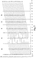
- Fig. 7 represents a chart of the correct tyre pressures charted over the internal temperature of the tyres;
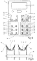
- Fig. 8 illustrates in a front view the remote control unit provided to be used with lorries and the like, and
- Fig. 9 shows in a diagrammed sectional view the arrangement of the transmitters in the case of a twin-wheeled axle.
-
- According to the drawings this device for controlling the pressure in the pneumatic tyres comprises: a
remote control unit 1 having a liquid-crystal display 2 and a receiver sensor 3 actuated by means of a pushbutton 4; and a pressure-measuringinstrument 5 installed in the wheel R advantageously in the vicinity of the inflation valve I of the tyre N, and connected to atransmitter 6. - The
remote control unit 1 incorporates means to visualize through thedisplay 2 the concrete pressures concerning specific tyres and corresponding to the different loads carried by the motor vehicle, said means being, respectively, the pushbutton orcontrol 7 and thepushbuttons - The remote control unit has also been provided to incorporate a
transmitter 12 actuated by means of a pushbutton 13 to transmit to an inflation machine or facility the command to inflate a tyre to the pressure visualized throughdisplay 2 ofremote control unit 1. - The remote control unit will as well comprise a
pushbutton 20 to switch off the device and clear thedisplay 2. - According to Fig. 3 the remote control unit comprises a
central processing unit 14 controlling all of the components of said control unit and thus governing all of the elements provided to communicate with the environment such as the radiofrequency receiver sensor 3 provided to receive the informations coming from themeasuring instrument 5, theradiofrequency emitter 15 provided to send the commands to themeasuring instrument 5, and theinfrared transmitter 12 for sending commands to the inflation machine. Atreference numeral 16 is indicated a keyset corresponding to each of the pushbuttons comprised by the remote control unit. - According to Fig. 4 the pressure-measuring instrument dos also comprise a
central processing unit 17 that will control all of the components of said instrument. This latter comprises as well atransmitter 6 provided to send the informations to theremote control unit 1, and areceiver sensor 18 that receives the commands from said control unit. The pickup comprised is themeasuring instrument 5 consisting in an absolute pressure sensing element that will measure the pressure inside the pneumatic tyre N. The connection of this pressure sensing element to the central processing unit is carried out through an intervening analog-to-digital converter 19. - With this arrangement, when bringing the
remote control unit 1 near to the pressure-measuringinstrument 5 and actuating the pushbutton 4 the pressure of the tyre N is displayed through thedisplay 2 of the remote control unit. When next actuating the pushbutton corresponding to the axle pertaining to the wheel being the object of the measurement (8 or 9) and to the load (10 or 11) borne at the moment the pressure recommended by the manufacturer will be instantly displayed through the display. - The block diagram of Fig. 5 incorporates a
sensor 20 measuring the temperature of the air inside the pneumatic tyre, said sensor being connected to thecentral processing unit 17 through an intervening analog-to-digital converter 21 and thus complementing the pressure-measuringinstrument 5 to be as well connected to the central processing unit by means of an analog-to-digital converter 19 thus forming a detector comprising thetransmitter 6 and thereceiver sensor 18. - The receiver sensor of the remote control unit picks up the pressure and temperature of the inside of the tyre, the microprocessor forming the central processing unit of said control unit carrying out the conversion of the pressure corresponding to the normal ambient temperature of the tyre to the equivalent pressure as per the temperature of the latter.
- After having previously actuated the pushbutton corresponding to the wheel to be controlled, when bringing the remote control unit near to the pressure-measuring instrument and actuating the pushbutton of said control unit the
display 2 of the latter then displays the actual pressure P1 of the tyre and the correct pressure P2 corresponding to it in accordance with its internal temperature. -
Display 2 can complementally display the internal temperature T of the tyre and the indication OK if the pressure is correct or NO OK↑ or NO OK↓ if the pressure is insufficient (increase pressure) or excessive (reduce pressure). - Once having acquired this information it will suffice to connect the wheel with a compressed-air dispenser such as an automated machine or facility at those petrol stations having them, and to pass to it said information collected by the remote control unit, for the inflation to be carried out to the correct pressure for the tyre in question.
- In Fig. 7 the vertical coordinate X indicates the pressure in bars, and the horizontal coordinate Y indicates temperatures in degrees centigrade. In column A appear the recommended pressures at a normal temperature that can be considered as being comprised between 5°C and 25°C, and columns B represent the correct pressures in accordance with the different temperatures.
- Thus for example if the correct pressure for a tyre is of 2.5 bars, if the internal temperature of the tyre sinks to a value comprised between 5°C and -15°C the correct pressure will be of 2.4 bars, and if said temperature rises to a value comprised between 40°C and 50°C the correct pressure will be of 2.7 bars.
- In the case of the remote control unit 1' provided with the display 2 a series of pushbuttons have been provided corresponding to the wheels of an empty lorry and to those of a fully-loaded lorry. The empty lorry is indicated at V, and the fully-loaded lorry is indicated at PC, the lorry being formed by a hauling member or tractor T and the trailer C, the tractor T having single wheels on the front axle and twin wheels on the rear axle, and the trailer C having three axles with twin wheels at their ends.
- In this case the pushbuttons of the remote control unit are: one 22 for the front wheels of the empty lorry and another one 23 for the front wheels of the fully-loaded lorry;
other pushbuttons 24 for the outer wheels of the twin wheels andother pushbuttons 25 for the inner wheels of said twin wheels corresponding to the empty lorry; andother pushbuttons 26 for the outer wheels of the twin wheels and yetother pushbuttons 27 for the inner wheels corresponding to the fully-loaded lorry. - In order to make it easier for the user to distinguish the different pushbuttons,
pushbuttons pushbuttons - Fig. 9 illustrates a twin-wheeled
axle 28 with the outer wheel RE and the inner wheel RI, each of said wheels comprising the assembly 5-6-18 on acarrier - Due to the fact that the
transmitter 6 of each wheel of each pair emits at a different frequency, when actuating the pushbutton corresponding to a given wheel only the pressure and temperature of the corresponding wheel will be captured. - It is understood that the remote control unit 1' will have the pushbuttons and sensors that are appropriate for each particular type of heavy vehicle, and that apart from the colour as a distinguishing element said pushbuttons and the assembly of elements to be arranged inside the wheel will also comprise any other distinguishing component or motif.
Claims (17)
- A device for controlling the pressure in the pneumatic tyres of motorcars and similar vehicles, characterized in that it comprises a remote control unit having a display and a receiver sensor actuated by means of a pushbutton, and a pressure-measuring instrument installed in the wheel and advantageously situated in the vicinity of the tyre inflation valve and connected to a transmitter, in such a way that when bringing the remote control unit near to the pressure-measuring instrument and actuating the pushbutton of the former the pressure of the tyre is displayed through the display of the remote control unit.
- A device as per claim 1, characterized in that the remote control unit incorporates means to visualize through the display the concrete pressures concerning specific tyres and corresponding to the different loads borne by the motor vehicle.
- A device as per claim 2, characterized in that the remote control unit incorporates a transmitter actuated by means of a pushbutton to transmit to an inflation machine or facility the command to inflate a tyre to the pressure visualized through the display of the remote control unit.
- A device as per claim 1, characterized in that the display is a liquid-crystal display.
- A device as per the previous claims, characterized in that all of the components integrating the remote control unit are incorporated into a conventional remote control unit such as that used to control the opening of the access doors of a motorcar or of a garage door, or the switching on of an alarm system and other devices.
- A device as per the previous claims, characterized in that the transmissions are carried out by means of radio signals, infrared rays, ultrasounds or other adequate means.
- A device as per claim 1, characterized in that the receiver sensor captures the internal pressure and temperature of the pneumatic tyre, the device carrying out the conversion of the pressure corresponding to the normal ambient temperature of the tyre to the equivalent pressure as per the temperature of said tyre.
- A device as per claim 7, characterized in that when bringing the remote control unit near to the pressure-measuring instrument and actuating the pushbutton of the latter the display visualizes the actual pressure of the tyre and the correct pressure corresponding to it in accordance with the temperature of said tyre.
- A device as per claim 8, characterized in that the internal temperature of the pneumatic tyre is complementally displayed through the display.
- A device as per claim 7, characterized in that the remote control unit is provided to receive a chip card charged to provide a given number of inflations at an automated machine or facility.
- A de vice as per claim 1, characterized in that in the case of vehicles with axles provided with twin wheels at their ends each wheel, i.e. the outer and inner wheel, of the pair has its transmitter emitting at a frequency different from that of the other wheel of the pair, the remote control unit comprising a receiver sensor for each of said two wheels in correspondence with the particular frequency of the transmitter of each of said wheels.
- A device as per claim 11, characterized in that the remote control unit has a pushbutton for each of said sensors.
- A device as per claims 11 and 12, characterized in that the transmitter corresponding to one of the wheels of each pair will have an appearance allowing to distinguish it from the transmitter of the other wheel of the pair, the pushbuttons of the sensors corresponding to said transmitters also having an appearance allowing to distinguish them from each other.
- A device as per claim 1, characterized in that the remote control unit comprises as a power source a rechargeable electric battery.
- A device as per claim 14, characterized in that the remote control unit comprises the ignition key for starting a motorcar or a similar vehicle, and the battery of said control unit is inductively recharged through the insertion of said key into the corresponding contact lock of the vehicle, said lock for such a purpose comprising the appropriate installation connected to the cell or battery of the vehicle itself.
- A device as per claim 14, characterized in that the rechargeable battery of the remote control unit is inductively recharged by means of arranging said control unit on a support provided for such a purpose and connected to the electrical network.
- A device as per claim 14, characterized in that the rechargeable battery of the remote control unit is recharged by means of connecting said control unit to the electrical network through an intervening transformer or the like.
Applications Claiming Priority (8)
| Application Number | Priority Date | Filing Date | Title |
|---|---|---|---|
| ES009802402A ES2164509B1 (en) | 1998-10-21 | 1998-10-21 | DEVICE FOR PRESSURE CONTROL IN CAR TIRES AND ANALOG VEHICLES. |
| ES009802403A ES2176047B1 (en) | 1998-10-21 | 1998-11-17 | IMPROVEMENTS INTRODUCED IN THE OBJECT OF THE MAIN PATENT N. 9802402: "DEVICE FOR PRESSURE CONTROL IN CAR TIRES AND ANALOG VEHICLES". |
| ES009900775A ES2167145B1 (en) | 1998-10-21 | 1999-04-14 | DEVICE FOR PRESSURE CONTROL IN CAR TIRES AND ANALOG VEHICLES IS AND ANALOG VEHICLES ". |
| ES009901408A ES2167163A1 (en) | 1998-10-21 | 1999-06-24 | Controlling device for the pressure in a pneumatic tire of a motorcar comprises display and receiver sensor actuated by push button and visual display with push buttons correspond to the state of the tires |
| ES9900775 | 1999-06-24 | ||
| ES9802402 | 1999-06-24 | ||
| ES9901408 | 1999-06-24 | ||
| ES9802403 | 1999-06-24 |
Publications (1)
| Publication Number | Publication Date |
|---|---|
| EP0995619A1 true EP0995619A1 (en) | 2000-04-26 |
Family
ID=27443937
Family Applications (1)
| Application Number | Title | Priority Date | Filing Date |
|---|---|---|---|
| EP99500131A Withdrawn EP0995619A1 (en) | 1998-10-21 | 1999-07-30 | A device for controlling the pressure in the pneumatic tyres of motocars and similar vehicles |
Country Status (2)
| Country | Link |
|---|---|
| EP (1) | EP0995619A1 (en) |
| JP (1) | JP2000127723A (en) |
Cited By (11)
| Publication number | Priority date | Publication date | Assignee | Title |
|---|---|---|---|---|
| EP1116608A1 (en) * | 2000-01-14 | 2001-07-18 | Huang, Teng-Wen | Apparatus for detecting pressure condition in a pneumatic tire |
| EP1172236A2 (en) * | 2000-06-26 | 2002-01-16 | Nokian Tyres PLC. | System for detecting and communicating operational characteristics of tires telecommunicationally and a method therefor |
| EP1136286A3 (en) * | 2000-03-22 | 2003-09-17 | Nolex AG | Tyre pressure indicator |
| GB2388197A (en) * | 2002-03-01 | 2003-11-05 | Lear Corp | Tire pressure monitor |
| EP1398736A1 (en) * | 2002-09-11 | 2004-03-17 | Alps Electric Co., Ltd. | Device and method for monitoring the tire pressure |
| US6933898B2 (en) | 2002-03-01 | 2005-08-23 | Lear Corporation | Antenna for tire pressure monitoring wheel electronic device |
| US8151127B2 (en) | 2000-07-26 | 2012-04-03 | Bridgestone Americas Tire Operations, Llc | System for conserving battery life in a battery operated device |
| US8266465B2 (en) | 2000-07-26 | 2012-09-11 | Bridgestone Americas Tire Operation, LLC | System for conserving battery life in a battery operated device |
| US9978265B2 (en) | 2016-04-11 | 2018-05-22 | Tti (Macao Commercial Offshore) Limited | Modular garage door opener |
| US10015898B2 (en) | 2016-04-11 | 2018-07-03 | Tti (Macao Commercial Offshore) Limited | Modular garage door opener |
| DE10164333B4 (en) | 2001-01-02 | 2019-05-09 | Trw Inc. | A remote-controlled convenience and information transmission system associated with a vehicle |
Families Citing this family (2)
| Publication number | Priority date | Publication date | Assignee | Title |
|---|---|---|---|---|
| JP2009222458A (en) * | 2008-03-14 | 2009-10-01 | Honda Motor Co Ltd | Tire internal pneumatic pressure display device |
| JP5731299B2 (en) * | 2011-07-04 | 2015-06-10 | 株式会社東海理化電機製作所 | Control device for tire pressure monitoring system |
Citations (6)
| Publication number | Priority date | Publication date | Assignee | Title |
|---|---|---|---|---|
| EP0016991A2 (en) * | 1979-03-12 | 1980-10-15 | Siemens Aktiengesellschaft | Tyre pressure monitoring device |
| GB2149951A (en) * | 1983-11-12 | 1985-06-19 | Michael Sacks | Security checking systems |
| WO1988007941A1 (en) * | 1987-04-16 | 1988-10-20 | Consolidated Technology Pty. Ltd. | Tyre deflation warning device |
| WO1993008035A1 (en) * | 1991-10-14 | 1993-04-29 | Rainer Achterholt | Process, device and valve for measuring and displaying tire pressure |
| EP0791488A1 (en) * | 1995-09-01 | 1997-08-27 | Fast Air, S.L. | Method and system for measuring and adjusting pressure of tyres |
| DE29715197U1 (en) * | 1997-08-23 | 1997-11-06 | Horn Armaturen | Device for checking and adjusting the tire pressure of motor vehicles |
-
1999
- 1999-07-30 EP EP99500131A patent/EP0995619A1/en not_active Withdrawn
- 1999-10-20 JP JP11334800A patent/JP2000127723A/en active Pending
Patent Citations (6)
| Publication number | Priority date | Publication date | Assignee | Title |
|---|---|---|---|---|
| EP0016991A2 (en) * | 1979-03-12 | 1980-10-15 | Siemens Aktiengesellschaft | Tyre pressure monitoring device |
| GB2149951A (en) * | 1983-11-12 | 1985-06-19 | Michael Sacks | Security checking systems |
| WO1988007941A1 (en) * | 1987-04-16 | 1988-10-20 | Consolidated Technology Pty. Ltd. | Tyre deflation warning device |
| WO1993008035A1 (en) * | 1991-10-14 | 1993-04-29 | Rainer Achterholt | Process, device and valve for measuring and displaying tire pressure |
| EP0791488A1 (en) * | 1995-09-01 | 1997-08-27 | Fast Air, S.L. | Method and system for measuring and adjusting pressure of tyres |
| DE29715197U1 (en) * | 1997-08-23 | 1997-11-06 | Horn Armaturen | Device for checking and adjusting the tire pressure of motor vehicles |
Cited By (18)
| Publication number | Priority date | Publication date | Assignee | Title |
|---|---|---|---|---|
| EP1116608A1 (en) * | 2000-01-14 | 2001-07-18 | Huang, Teng-Wen | Apparatus for detecting pressure condition in a pneumatic tire |
| EP1136286A3 (en) * | 2000-03-22 | 2003-09-17 | Nolex AG | Tyre pressure indicator |
| EP1609629A1 (en) * | 2000-06-26 | 2005-12-28 | Nokian Tyres PLC. | System for detecting and communicating operational characteristics of tires telecommunicationally |
| EP1172236A3 (en) * | 2000-06-26 | 2004-01-21 | Nokian Tyres PLC. | System for detecting and communicating operational characteristics of tires telecommunicationally and a method therefor |
| EP1172236A2 (en) * | 2000-06-26 | 2002-01-16 | Nokian Tyres PLC. | System for detecting and communicating operational characteristics of tires telecommunicationally and a method therefor |
| US8266465B2 (en) | 2000-07-26 | 2012-09-11 | Bridgestone Americas Tire Operation, LLC | System for conserving battery life in a battery operated device |
| US8151127B2 (en) | 2000-07-26 | 2012-04-03 | Bridgestone Americas Tire Operations, Llc | System for conserving battery life in a battery operated device |
| DE10164333B4 (en) | 2001-01-02 | 2019-05-09 | Trw Inc. | A remote-controlled convenience and information transmission system associated with a vehicle |
| GB2388197B (en) * | 2002-03-01 | 2004-06-09 | Lear Corp | System and method for tire pressure monitoring with optimal tire pressure indication during tire pressure adjustment |
| US6933898B2 (en) | 2002-03-01 | 2005-08-23 | Lear Corporation | Antenna for tire pressure monitoring wheel electronic device |
| GB2388197A (en) * | 2002-03-01 | 2003-11-05 | Lear Corp | Tire pressure monitor |
| US7124002B2 (en) | 2002-09-11 | 2006-10-17 | Alps Electric Co., Ltd. | Tire air pressure abnormality warning device and method |
| EP1398736A1 (en) * | 2002-09-11 | 2004-03-17 | Alps Electric Co., Ltd. | Device and method for monitoring the tire pressure |
| US9978265B2 (en) | 2016-04-11 | 2018-05-22 | Tti (Macao Commercial Offshore) Limited | Modular garage door opener |
| US10015898B2 (en) | 2016-04-11 | 2018-07-03 | Tti (Macao Commercial Offshore) Limited | Modular garage door opener |
| US10127806B2 (en) | 2016-04-11 | 2018-11-13 | Tti (Macao Commercial Offshore) Limited | Methods and systems for controlling a garage door opener accessory |
| US10157538B2 (en) | 2016-04-11 | 2018-12-18 | Tti (Macao Commercial Offshore) Limited | Modular garage door opener |
| US10237996B2 (en) | 2016-04-11 | 2019-03-19 | Tti (Macao Commercial Offshore) Limited | Modular garage door opener |
Also Published As
| Publication number | Publication date |
|---|---|
| JP2000127723A (en) | 2000-05-09 |
Similar Documents
| Publication | Publication Date | Title |
|---|---|---|
| EP0995619A1 (en) | A device for controlling the pressure in the pneumatic tyres of motocars and similar vehicles | |
| US6034596A (en) | Motor vehicle tire pressure and temperature sensing system | |
| KR100370740B1 (en) | Tire air pressure monitoring apparatus and eternal communication apparatus | |
| US6748797B2 (en) | Method and apparatus for monitoring tires | |
| US6972671B2 (en) | Device mounted on vehicles with pneumatic-tired wheels, for use in a tire pressure monitoring system | |
| US6441727B1 (en) | Arrangement and method of vehicle tire identification | |
| KR101121130B1 (en) | System and method for detecting positions of tires | |
| US7250852B1 (en) | Handheld tire sensor communication device | |
| US20020130771A1 (en) | Vehicle wheel monitoring system | |
| US20050200464A1 (en) | Method and system of notifying of use of a tire in a tire pressure monitoring system for an automotive vehicle | |
| JPH07507513A (en) | Air pressure monitoring device for pneumatic tires for vehicles | |
| US6784794B1 (en) | Method and apparatus for reminding the vehicle operator to refill the spare tire in a tire pressure monitoring system | |
| GB2316209A (en) | Checking tyre pressures | |
| US20050270148A1 (en) | Trailer tire monitoring system and method | |
| KR101443155B1 (en) | Tire pressure monitoring system capable of sensor location set-up | |
| JP3815310B2 (en) | Air pressure information display system for vehicle tires | |
| US7373228B2 (en) | Sensor ID registration method of tire air pressure monitoring apparatus | |
| KR101898098B1 (en) | a temperature sensing device for a wheel bearing | |
| US20080094197A1 (en) | Tire pressure monitoring system with bidirectional communication function | |
| US7308344B2 (en) | Tire rotation assisting apparatus | |
| US7102492B2 (en) | Vehicle tracking system | |
| WO2015190642A1 (en) | System for providing tire total management service | |
| EP1477336A1 (en) | Tire pressure detecting device | |
| WO2000066374A1 (en) | System to monitor conditions in a fluid-containing member and method to monitoring said conditions | |
| CN100507966C (en) | Bidirectional communication linking system of tire pressure detector |
Legal Events
| Date | Code | Title | Description |
|---|---|---|---|
| PUAI | Public reference made under article 153(3) epc to a published international application that has entered the european phase |
Free format text: ORIGINAL CODE: 0009012 |
|
| AK | Designated contracting states |
Kind code of ref document: A1 Designated state(s): AT BE CH CY DE DK ES FI FR GB GR IE IT LI LU MC NL PT SE |
|
| AX | Request for extension of the european patent |
Free format text: AL;LT;LV;MK;RO;SI |
|
| STAA | Information on the status of an ep patent application or granted ep patent |
Free format text: STATUS: THE APPLICATION HAS BEEN WITHDRAWN |
|
| 18W | Application withdrawn |
Withdrawal date: 20001013 |