EP0995018B1 - Modular silencer - Google Patents
Modular silencer Download PDFInfo
- Publication number
- EP0995018B1 EP0995018B1 EP98932937A EP98932937A EP0995018B1 EP 0995018 B1 EP0995018 B1 EP 0995018B1 EP 98932937 A EP98932937 A EP 98932937A EP 98932937 A EP98932937 A EP 98932937A EP 0995018 B1 EP0995018 B1 EP 0995018B1
- Authority
- EP
- European Patent Office
- Prior art keywords
- pot
- pots
- pipe
- dome head
- open end
- Prior art date
- Legal status (The legal status is an assumption and is not a legal conclusion. Google has not performed a legal analysis and makes no representation as to the accuracy of the status listed.)
- Expired - Lifetime
Links
Images


Classifications
-
- F—MECHANICAL ENGINEERING; LIGHTING; HEATING; WEAPONS; BLASTING
- F01—MACHINES OR ENGINES IN GENERAL; ENGINE PLANTS IN GENERAL; STEAM ENGINES
- F01N—GAS-FLOW SILENCERS OR EXHAUST APPARATUS FOR MACHINES OR ENGINES IN GENERAL; GAS-FLOW SILENCERS OR EXHAUST APPARATUS FOR INTERNAL COMBUSTION ENGINES
- F01N13/00—Exhaust or silencing apparatus characterised by constructional features ; Exhaust or silencing apparatus, or parts thereof, having pertinent characteristics not provided for in, or of interest apart from, groups F01N1/00 - F01N5/00, F01N9/00, F01N11/00
- F01N13/18—Construction facilitating manufacture, assembly, or disassembly
- F01N13/1838—Construction facilitating manufacture, assembly, or disassembly characterised by the type of connection between parts of exhaust or silencing apparatus, e.g. between housing and tubes, between tubes and baffles
-
- F—MECHANICAL ENGINEERING; LIGHTING; HEATING; WEAPONS; BLASTING
- F01—MACHINES OR ENGINES IN GENERAL; ENGINE PLANTS IN GENERAL; STEAM ENGINES
- F01N—GAS-FLOW SILENCERS OR EXHAUST APPARATUS FOR MACHINES OR ENGINES IN GENERAL; GAS-FLOW SILENCERS OR EXHAUST APPARATUS FOR INTERNAL COMBUSTION ENGINES
- F01N1/00—Silencing apparatus characterised by method of silencing
- F01N1/02—Silencing apparatus characterised by method of silencing by using resonance
- F01N1/04—Silencing apparatus characterised by method of silencing by using resonance having sound-absorbing materials in resonance chambers
-
- F—MECHANICAL ENGINEERING; LIGHTING; HEATING; WEAPONS; BLASTING
- F01—MACHINES OR ENGINES IN GENERAL; ENGINE PLANTS IN GENERAL; STEAM ENGINES
- F01N—GAS-FLOW SILENCERS OR EXHAUST APPARATUS FOR MACHINES OR ENGINES IN GENERAL; GAS-FLOW SILENCERS OR EXHAUST APPARATUS FOR INTERNAL COMBUSTION ENGINES
- F01N1/00—Silencing apparatus characterised by method of silencing
- F01N1/08—Silencing apparatus characterised by method of silencing by reducing exhaust energy by throttling or whirling
- F01N1/085—Silencing apparatus characterised by method of silencing by reducing exhaust energy by throttling or whirling using a central core throttling gas passage
-
- F—MECHANICAL ENGINEERING; LIGHTING; HEATING; WEAPONS; BLASTING
- F01—MACHINES OR ENGINES IN GENERAL; ENGINE PLANTS IN GENERAL; STEAM ENGINES
- F01N—GAS-FLOW SILENCERS OR EXHAUST APPARATUS FOR MACHINES OR ENGINES IN GENERAL; GAS-FLOW SILENCERS OR EXHAUST APPARATUS FOR INTERNAL COMBUSTION ENGINES
- F01N1/00—Silencing apparatus characterised by method of silencing
- F01N1/08—Silencing apparatus characterised by method of silencing by reducing exhaust energy by throttling or whirling
- F01N1/086—Silencing apparatus characterised by method of silencing by reducing exhaust energy by throttling or whirling having means to impart whirling motion to the gases
-
- F—MECHANICAL ENGINEERING; LIGHTING; HEATING; WEAPONS; BLASTING
- F01—MACHINES OR ENGINES IN GENERAL; ENGINE PLANTS IN GENERAL; STEAM ENGINES
- F01N—GAS-FLOW SILENCERS OR EXHAUST APPARATUS FOR MACHINES OR ENGINES IN GENERAL; GAS-FLOW SILENCERS OR EXHAUST APPARATUS FOR INTERNAL COMBUSTION ENGINES
- F01N1/00—Silencing apparatus characterised by method of silencing
- F01N1/08—Silencing apparatus characterised by method of silencing by reducing exhaust energy by throttling or whirling
- F01N1/089—Silencing apparatus characterised by method of silencing by reducing exhaust energy by throttling or whirling using two or more expansion chambers in series
-
- F—MECHANICAL ENGINEERING; LIGHTING; HEATING; WEAPONS; BLASTING
- F01—MACHINES OR ENGINES IN GENERAL; ENGINE PLANTS IN GENERAL; STEAM ENGINES
- F01N—GAS-FLOW SILENCERS OR EXHAUST APPARATUS FOR MACHINES OR ENGINES IN GENERAL; GAS-FLOW SILENCERS OR EXHAUST APPARATUS FOR INTERNAL COMBUSTION ENGINES
- F01N1/00—Silencing apparatus characterised by method of silencing
- F01N1/14—Silencing apparatus characterised by method of silencing by adding air to exhaust gases
-
- F—MECHANICAL ENGINEERING; LIGHTING; HEATING; WEAPONS; BLASTING
- F01—MACHINES OR ENGINES IN GENERAL; ENGINE PLANTS IN GENERAL; STEAM ENGINES
- F01N—GAS-FLOW SILENCERS OR EXHAUST APPARATUS FOR MACHINES OR ENGINES IN GENERAL; GAS-FLOW SILENCERS OR EXHAUST APPARATUS FOR INTERNAL COMBUSTION ENGINES
- F01N13/00—Exhaust or silencing apparatus characterised by constructional features ; Exhaust or silencing apparatus, or parts thereof, having pertinent characteristics not provided for in, or of interest apart from, groups F01N1/00 - F01N5/00, F01N9/00, F01N11/00
- F01N13/18—Construction facilitating manufacture, assembly, or disassembly
- F01N13/1888—Construction facilitating manufacture, assembly, or disassembly the housing of the assembly consisting of two or more parts, e.g. two half-shells
- F01N13/1894—Construction facilitating manufacture, assembly, or disassembly the housing of the assembly consisting of two or more parts, e.g. two half-shells the parts being assembled in longitudinal direction
-
- F—MECHANICAL ENGINEERING; LIGHTING; HEATING; WEAPONS; BLASTING
- F01—MACHINES OR ENGINES IN GENERAL; ENGINE PLANTS IN GENERAL; STEAM ENGINES
- F01N—GAS-FLOW SILENCERS OR EXHAUST APPARATUS FOR MACHINES OR ENGINES IN GENERAL; GAS-FLOW SILENCERS OR EXHAUST APPARATUS FOR INTERNAL COMBUSTION ENGINES
- F01N3/00—Exhaust or silencing apparatus having means for purifying, rendering innocuous, or otherwise treating exhaust
- F01N3/08—Exhaust or silencing apparatus having means for purifying, rendering innocuous, or otherwise treating exhaust for rendering innocuous
- F01N3/10—Exhaust or silencing apparatus having means for purifying, rendering innocuous, or otherwise treating exhaust for rendering innocuous by thermal or catalytic conversion of noxious components of exhaust
- F01N3/24—Exhaust or silencing apparatus having means for purifying, rendering innocuous, or otherwise treating exhaust for rendering innocuous by thermal or catalytic conversion of noxious components of exhaust characterised by constructional aspects of converting apparatus
- F01N3/28—Construction of catalytic reactors
- F01N3/2882—Catalytic reactors combined or associated with other devices, e.g. exhaust silencers or other exhaust purification devices
- F01N3/2885—Catalytic reactors combined or associated with other devices, e.g. exhaust silencers or other exhaust purification devices with exhaust silencers in a single housing
-
- F—MECHANICAL ENGINEERING; LIGHTING; HEATING; WEAPONS; BLASTING
- F01—MACHINES OR ENGINES IN GENERAL; ENGINE PLANTS IN GENERAL; STEAM ENGINES
- F01N—GAS-FLOW SILENCERS OR EXHAUST APPARATUS FOR MACHINES OR ENGINES IN GENERAL; GAS-FLOW SILENCERS OR EXHAUST APPARATUS FOR INTERNAL COMBUSTION ENGINES
- F01N2240/00—Combination or association of two or more different exhaust treating devices, or of at least one such device with an auxiliary device, not covered by indexing codes F01N2230/00 or F01N2250/00, one of the devices being
- F01N2240/10—Combination or association of two or more different exhaust treating devices, or of at least one such device with an auxiliary device, not covered by indexing codes F01N2230/00 or F01N2250/00, one of the devices being a heat accumulator
-
- F—MECHANICAL ENGINEERING; LIGHTING; HEATING; WEAPONS; BLASTING
- F01—MACHINES OR ENGINES IN GENERAL; ENGINE PLANTS IN GENERAL; STEAM ENGINES
- F01N—GAS-FLOW SILENCERS OR EXHAUST APPARATUS FOR MACHINES OR ENGINES IN GENERAL; GAS-FLOW SILENCERS OR EXHAUST APPARATUS FOR INTERNAL COMBUSTION ENGINES
- F01N2330/00—Structure of catalyst support or particle filter
- F01N2330/08—Granular material
-
- F—MECHANICAL ENGINEERING; LIGHTING; HEATING; WEAPONS; BLASTING
- F01—MACHINES OR ENGINES IN GENERAL; ENGINE PLANTS IN GENERAL; STEAM ENGINES
- F01N—GAS-FLOW SILENCERS OR EXHAUST APPARATUS FOR MACHINES OR ENGINES IN GENERAL; GAS-FLOW SILENCERS OR EXHAUST APPARATUS FOR INTERNAL COMBUSTION ENGINES
- F01N2450/00—Methods or apparatus for fitting, inserting or repairing different elements
- F01N2450/06—Inserting sound absorbing material into a chamber
-
- F—MECHANICAL ENGINEERING; LIGHTING; HEATING; WEAPONS; BLASTING
- F01—MACHINES OR ENGINES IN GENERAL; ENGINE PLANTS IN GENERAL; STEAM ENGINES
- F01N—GAS-FLOW SILENCERS OR EXHAUST APPARATUS FOR MACHINES OR ENGINES IN GENERAL; GAS-FLOW SILENCERS OR EXHAUST APPARATUS FOR INTERNAL COMBUSTION ENGINES
- F01N2450/00—Methods or apparatus for fitting, inserting or repairing different elements
- F01N2450/20—Methods or apparatus for fitting, inserting or repairing different elements by mechanical joints, e.g. by deforming housing, tube, baffle plate or parts thereof
-
- F—MECHANICAL ENGINEERING; LIGHTING; HEATING; WEAPONS; BLASTING
- F01—MACHINES OR ENGINES IN GENERAL; ENGINE PLANTS IN GENERAL; STEAM ENGINES
- F01N—GAS-FLOW SILENCERS OR EXHAUST APPARATUS FOR MACHINES OR ENGINES IN GENERAL; GAS-FLOW SILENCERS OR EXHAUST APPARATUS FOR INTERNAL COMBUSTION ENGINES
- F01N2450/00—Methods or apparatus for fitting, inserting or repairing different elements
- F01N2450/22—Methods or apparatus for fitting, inserting or repairing different elements by welding or brazing
-
- F—MECHANICAL ENGINEERING; LIGHTING; HEATING; WEAPONS; BLASTING
- F01—MACHINES OR ENGINES IN GENERAL; ENGINE PLANTS IN GENERAL; STEAM ENGINES
- F01N—GAS-FLOW SILENCERS OR EXHAUST APPARATUS FOR MACHINES OR ENGINES IN GENERAL; GAS-FLOW SILENCERS OR EXHAUST APPARATUS FOR INTERNAL COMBUSTION ENGINES
- F01N2470/00—Structure or shape of gas passages, pipes or tubes
- F01N2470/16—Plurality of inlet tubes, e.g. discharging into different chambers
-
- F—MECHANICAL ENGINEERING; LIGHTING; HEATING; WEAPONS; BLASTING
- F01—MACHINES OR ENGINES IN GENERAL; ENGINE PLANTS IN GENERAL; STEAM ENGINES
- F01N—GAS-FLOW SILENCERS OR EXHAUST APPARATUS FOR MACHINES OR ENGINES IN GENERAL; GAS-FLOW SILENCERS OR EXHAUST APPARATUS FOR INTERNAL COMBUSTION ENGINES
- F01N2470/00—Structure or shape of gas passages, pipes or tubes
- F01N2470/18—Structure or shape of gas passages, pipes or tubes the axis of inlet or outlet tubes being other than the longitudinal axis of apparatus
-
- F—MECHANICAL ENGINEERING; LIGHTING; HEATING; WEAPONS; BLASTING
- F01—MACHINES OR ENGINES IN GENERAL; ENGINE PLANTS IN GENERAL; STEAM ENGINES
- F01N—GAS-FLOW SILENCERS OR EXHAUST APPARATUS FOR MACHINES OR ENGINES IN GENERAL; GAS-FLOW SILENCERS OR EXHAUST APPARATUS FOR INTERNAL COMBUSTION ENGINES
- F01N2470/00—Structure or shape of gas passages, pipes or tubes
- F01N2470/26—Tubes being formed by extrusion, drawing or rolling
-
- F—MECHANICAL ENGINEERING; LIGHTING; HEATING; WEAPONS; BLASTING
- F01—MACHINES OR ENGINES IN GENERAL; ENGINE PLANTS IN GENERAL; STEAM ENGINES
- F01N—GAS-FLOW SILENCERS OR EXHAUST APPARATUS FOR MACHINES OR ENGINES IN GENERAL; GAS-FLOW SILENCERS OR EXHAUST APPARATUS FOR INTERNAL COMBUSTION ENGINES
- F01N2470/00—Structure or shape of gas passages, pipes or tubes
- F01N2470/30—Tubes with restrictions, i.e. venturi or the like, e.g. for sucking air or measuring mass flow
-
- F—MECHANICAL ENGINEERING; LIGHTING; HEATING; WEAPONS; BLASTING
- F01—MACHINES OR ENGINES IN GENERAL; ENGINE PLANTS IN GENERAL; STEAM ENGINES
- F01N—GAS-FLOW SILENCERS OR EXHAUST APPARATUS FOR MACHINES OR ENGINES IN GENERAL; GAS-FLOW SILENCERS OR EXHAUST APPARATUS FOR INTERNAL COMBUSTION ENGINES
- F01N2490/00—Structure, disposition or shape of gas-chambers
- F01N2490/02—Two or more expansion chambers in series connected by means of tubes
- F01N2490/04—Two or more expansion chambers in series connected by means of tubes the gases flowing longitudinally from inlet to outlet only in one direction
-
- F—MECHANICAL ENGINEERING; LIGHTING; HEATING; WEAPONS; BLASTING
- F01—MACHINES OR ENGINES IN GENERAL; ENGINE PLANTS IN GENERAL; STEAM ENGINES
- F01N—GAS-FLOW SILENCERS OR EXHAUST APPARATUS FOR MACHINES OR ENGINES IN GENERAL; GAS-FLOW SILENCERS OR EXHAUST APPARATUS FOR INTERNAL COMBUSTION ENGINES
- F01N2490/00—Structure, disposition or shape of gas-chambers
- F01N2490/02—Two or more expansion chambers in series connected by means of tubes
- F01N2490/06—Two or more expansion chambers in series connected by means of tubes the gases flowing longitudinally from inlet to outlet in opposite directions
-
- F—MECHANICAL ENGINEERING; LIGHTING; HEATING; WEAPONS; BLASTING
- F01—MACHINES OR ENGINES IN GENERAL; ENGINE PLANTS IN GENERAL; STEAM ENGINES
- F01N—GAS-FLOW SILENCERS OR EXHAUST APPARATUS FOR MACHINES OR ENGINES IN GENERAL; GAS-FLOW SILENCERS OR EXHAUST APPARATUS FOR INTERNAL COMBUSTION ENGINES
- F01N2490/00—Structure, disposition or shape of gas-chambers
- F01N2490/15—Plurality of resonance or dead chambers
- F01N2490/155—Plurality of resonance or dead chambers being disposed one after the other in flow direction
-
- F—MECHANICAL ENGINEERING; LIGHTING; HEATING; WEAPONS; BLASTING
- F01—MACHINES OR ENGINES IN GENERAL; ENGINE PLANTS IN GENERAL; STEAM ENGINES
- F01N—GAS-FLOW SILENCERS OR EXHAUST APPARATUS FOR MACHINES OR ENGINES IN GENERAL; GAS-FLOW SILENCERS OR EXHAUST APPARATUS FOR INTERNAL COMBUSTION ENGINES
- F01N2490/00—Structure, disposition or shape of gas-chambers
- F01N2490/16—Chambers with particular shapes, e.g. spherical
Definitions
- the invention relates to silencers, and more particularly to economical silencer constructions, components, and methods.
- Silencers are used in various applications for quieting noise, including mufflers for internal combustion engines, and including other devices such as rotary blowers, compressors, pumps, and the like. Silencers may be used on intake and/or exhaust systems, and may pass various intake and/or exhaust fluids therethrough, including gas and liquid.
- Silencers are typically characterized by complex constructions and labor intensive manufacturing methods, particularly welding, all contributing to high cost.
- the present invention provides simplified constructions and methods in combination with a modular building block approach, to lower cost.
- the invention also provides simplified, cost effective insulation techniques.
- US 5,020,631 discloses a silencer having a case formed from first and second case elements with an axial tube through both case elements. A third case element may also be provided.
- the present invention provides a modular silencer as set out in claim 1.
- the invention also provides a method for making a modular silencer as set out in claim 5.
- Fig. 1 is a sectional view of a silencer constructed in accordance with the invention.
- Fig. 2 is a sectional view taken along line 2-2 of Fig. 1.
- Fig. 3 is a view of a portion of the structure of Fig. 1 and shows a further embodiment.
- Fig. 4 is a sectional view of a silencer constructed in accordance with the invention.
- Fig. 5 is a sectional view of a silencer constructed in accordance with the invention.
- Fig. 6 is a sectional view of a silencer constructed in accordance with the invention.
- Fig. 7 is a sectional view taken along line 7-7 of Fig. 6.
- Fig. 8 is a sectional view of a silencer.
- Fig. 9 is a sectional view of a silencer.
- Fig. 10 is a sectional view of a silencer constructed in accordance with the invention.
- Figs. 11-20 sequentially illustrate manufacturing steps for constructing a silencer component.
- Figs. 21-23 sequentially illustrate an insulation technique.
- Fig. 24 is an exploded perspective view of the structure of Fig. 1.
- Fig. 25 is an assembled perspective view of the structure of Fig. 1.
- Fig. 26 is a sectional view of a silencer component.
- Fig. 27 is a sectional view of a plug silencer.
- Fig. 28 is like Fig. 27 and shows a further example.
- Fig. 29 is a sectional view of a spark arrestor silencer
- Fig. 30 is a sectional view taken along line 30-30 of Fig. 29.
- Fig. 31 is a sectional view taken along line 31-31 of Fig. 30.
- Fig. 32 is a sectional view of a spark arrestor silencer constructed in accordance with the invention.
- Fig. 33 is a sectional view taken along line 33-33 of Fig. 32.
- Fig. 34 is a sectional view of an aspirating silencer.
- Fig. 35 is a sectional view of a catalytic silencer.
- Fig. 36 is like Fig. 35 and shows a further example.
- Fig. 37 is like Fig. 35 and shows a further example.
- Fig. 38 is a sectional view of a heat recovery silencer.
- Fig. 39 is a sectional view of a silencer.
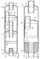
- Fig. 1 shows a modular silencer or muffler 30 constructed in accordance with an embodiment of the invention, including a plurality of axially aligned drawn pots.
- Draw forming of pots is known in the prior art, for example as shown in US Patent 5,020,631, and is briefly illustrated in Figs. 11 and 12.
- a flat sheet of metal 32, Fig. 11, is gradually and repetitively deformed and cold flowed by a mandrel to a pot or can 34 as shown in Fig. 12.
- the pot is trimmed to a desired length by knife blade 36, Fig. 13.
- Pot 34 has an axially extending continuous sidewall 38 open at one end 40 and having an integral dome head 42 at the other axial end.
- Pot 48 is formed as above described and then further by punching a hole through its dome head with punch 50, Fig. 15, and then inserting a pipe 52, Fig. 16, through such hole and welding the pipe to the dome head of the pot by welding gun 54.
- Pot 46, Fig. 1 is similarly made, except that the hole in the dome head is punched at a location laterally offset from the axial centerline, for example as shown at the middle pot in Fig. 24.
- Pot 44 is similarly constructed as pot 48, except that an additional step, Fig. 14, is provided wherein a tool 56 swages, necks or joggles the open end of the pot to a reduced diameter at 58. The swaging enables telescoped nesting engagement of pots 44 and 46, to be described.
- pot 46 is swaged at its open end rather than pot 44, to provide the telescoped nesting engagement.
- Fig. 1 The construction in Fig. 1 includes first and second axially aligned drawn pots 44 and 46.
- Pot 44 has an axially extending continuous sidewall 60 initially open at axial end 62 and having an integral dome head 64 at the other axial end.
- Pot 46 has an axially extending continuous sidewall 66 initially open at axial end 68 and having an integral dome head 70 at the other axial end.
- Inlet pipe 72 extends axially through dome head 64 along the axial centerline of the pots. In an alternate embodiment, inlet pipe 72 extends axially through dome head 64 and is laterally offset from the axial centerline of the pots. In another alternate embodiment, inlet pipe 72 extends through dome head 64 at an angle relative to the axial centerline of the pots, for example 30° or some other angle.
- the inlet pipe intersects the dome head at a point laterally offset from the axial centerline of the pots.
- Intermediate connecting pipe 74 extends axially through dome head 70 and is laterally offset from the axial centerline of the pots, Figs. 1 and 2.
- the construction of Fig. 1 further includes a third axially aligned drawn pot 48 having an axially extending continuous sidewall 76 initially open at axial end 78 and having an integral dome head 80 at the other axial end.
- Outlet pipe 82 extends axially through dome head 80 along the axial centerline of the pots.
- pipe 82 may be laterally offset from the axial centerline of the pots, or may extend at an angle relative to such centerline, as above described in conjunction with pipe 72.
- the pots are welded together by circumferential weldments 84 and 86 at the respective interfaces of the pots by welder 88, Fig. 25.
- dome head 64 has another hole punched therethrough, with a sleeve 90 inserted therein and welded thereto at weldment 91 and receiving a drain plug 92 in threaded relation.
- Pipe 74 has a plurality of perforations such as 75 through the sidewall thereof.
- Pipes 72 and 82 have perforations such as 73 and 83 along the portions thereof within the pots.
- the exterior portions of pipes 72 and 82 are solid, and are threaded for connection to other components or piping as desired.
- pipe 74 is laterally offset from pipe 72 and is laterally offset from pipe 82.
- Pipes 74 and 82 are axially overlapped such that fluid, gas or liquid, inlet or exhaust, flows axially in one direction, e.g. rightwardly in Fig. 1, along path 94, then reverses itself and flows axially in the opposite direction along path 96 laterally adjacent path 94, and then reverses itself again and flows axially rightwardly along path 98 laterally adjacent paths 94 and 96.
- Path 94 is through pipe 74 through dome head 70.
- Path 98 is through pipe 82 through dome head 80.
- Pipes 72 and 74 have axial ends 100 and 102, respectively, axially spaced from each other in nonoverlapping relation such that fluid may flow at 104 from axial end 100 of pipe 72 to axial end 102 of pipe 74 without reversing itself.
- Pipes 72 and 82 are axially spaced from each other on axially distally opposite sides of pipe 74.
- Fig. 3 shows a further embodiment of the construction of Fig. 1.
- Flanges 104 and 106 are welded to the ends of respective pipes 72 and 82, to facilitate mounting in flanged installations.
- Fig. 4 shows a silencer 110 with first, second, third and fourth axially aligned drawn pots 112, 114, 116, 118.
- Inlet pipe 120 extends axially through dome head 122 of pot 112 along the axial centerline thereof.
- Intermediate connecting pipe 124 extends axially through dome head 126 of pot 114 along the axial centerline thereof.
- Intermediate connecting pipe 128 extends axially through dome head 130 of pot 116 and is laterally offset from the axial centerline of the pots.
- Outlet pipe 132 extends axially through dome head 134 of pot 118 along the axial centerline thereof.
- Axial ends 136 and 138 of respective pipes 124 and 128 are axially overlapped. All of the remaining axial ends of the pipes are axially spaced from each other in nonoverlapping relation.
- Fig. 5 shows a silencer 140 having first, second and third axially aligned drawn pots 142, 144, 146.
- Inlet pipe 148 extends axially through dome head 150 of pot 142 along the axial centerline thereof, and through insulation 152, to be described.
- Intermediate connecting pipe 154 extends axially through dome head 156 of pot 144 and is laterally offset from the axial centerline of the pots.
- Outlet pipe 158 extends axially through dome head 160 of pot 146 along the axial centerline thereof.
- Fig. 6 shows a silencer 162 having first, second and third axially aligned drawn pots 164, 166, 168.
- Inlet pipe 170 extends axially through dome head 172 of pot 164 along the axial centerline thereof.
- a pair of intermediate connecting pipes 174 and 176, Fig. 7, extend through dome head 178 of pot 166 and are each laterally offset from the axial centerline of the pots.
- Pipes 174 and 176 are further supported by a cross brace 180 welded therebetween.
- Outlet pipe 182 extends axially through dome head 184 of pot 168 along the axial centerline thereof.
- Pipes 170 and 182 are axially spaced from each other on axially distally opposite sides of pipes 174 and 176.
- Pipes 174 and 176 are laterally offset from pipes 170 and 182. Pipes 174 and 176 extend in parallel laterally spaced relation, each having an axial end 186 axially spaced from axial end 188 of pipe 170 in nonoverlapping relation. Pipes 174 and 176 have an axial end 190 axially spaced from axial end 192 of pipe 182 in nonoverlapping relation.
- Fig. 8 shows a silencer 200 having first, second, third and fourth drawn pots 202, 204. 206, 208, each having an axially extending continuous sidewall open at one axial end and having an integral dome head at the other axial end.
- Pot 202 concentrically surrounds pot 204.
- Pot 206 concentrically surrounds pot 208.
- Pots 202 and 206 are coaxially aligned and joined at their open ends 210 and 212 to form a first enclosure 214.
- Pots 204 and 208 are coaxially aligned and joined at their open ends 216 and 218 to form a second enclosure 220 within enclosure 214.
- Inlet pipe 222 extends axially through dome head 224 of pot 202 and through dome head 226 of pot 204 along the axial centerline thereof.
- Outlet pipe 228 extends axially through dome head 230 of pot 206 and through dome head 232 of pot 208 along the axial centerline thereof.
- Pipes 222 and 228 have inner axial ends 234 and 236, respectively, within enclosure 220 and axially spaced from each other in nonoverlapping relation.
- Dome head 224 of pot 202 is axially spaced from dome head 226 of pot 204 by an axial gap 225 which is spanned by pipe 222.
- Dome head 230 of pot 206 is axially spaced from dome head 232 of pot 208 by an axial gap 231 which is spanned by pipe 228.
- Pots 204 and 208 are perforated along their sidewalls 238 and 240.
- Pots 202 and 206 forming enclosure 214 are coaxial with pots 204 and 208 forming enclosure 220.
- Enclosure 220 is spaced radially inwardly of enclosure 214 by an annular gap 215.
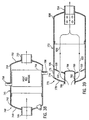
- Fig. 9 shows a silencer 250 including first, second, third and fourth axially aligned drawn pots 252, 254, 256, 258, each having an axially extending continuous sidewall open at one axial end and having an integral dome head at the other axial end.
- Pots 252 and 254 are connected at their open ends 260 and 262 to form a first compartment 264.
- Pots 256 and 258 are connected at their open ends 266 and 268 to form a second compartment 270.
- An intermediate cylindrical sidewall 272 extends axially between pots 254 and 256.
- Intermediate cylindrical sidewall 272 has a leftward axial end 274 connected to the junction of cylindrical sidewall 276 and dome head 278 of pot 254.
- Intermediate cylindrical sidewall 272 has a rightward axial end 280 connected to the junction of cylindrical sidewall 282 and dome head 284 of pot 256.
- the noted connection of intermediate cylindrical sidewall 272 to pots 254 and 256 forms a third compartment 286.
- Inlet pipe 288 extends axially through dome head 290 of pot 252 along the axial centerline thereof and into compartment 264.
- Outlet pipe 292 extends axially through dome head 294 of pot 258 along the axial centerline thereof and into compartment 270.
- Outlet or inlet pipe 296 extends radially through intermediate cylindrical sidewall 272 and into compartment 286.
- Intermediate connecting pipe 298 extends axially through dome head 278 of pot 254 and is laterally offset from the axial centerline thereof.
- Pipe 298 extends between compartments 286 and 264 and communicates with pipe 288 in compartment 264.
- Intermediate connecting pipe 300 extends axially through dome head 284 of pot 256 and is laterally offset from the axial centerline thereof.
- Pipe 300 extends between compartments 286 and 270 and communicates with pipe 292 in compartment 270.
- Pipes 296, 298 and 300 communicate with each other in compartment 286.
- Fig. 10 shows a silencer 310 including first, second and third axially aligned drawn pots 312, 314, 316, each having an axially extending continuous sidewall open at one axial end and having an integral dome head at the other axial end.
- a fourth drawn pot 318 has a continuous sidewall 320 initially open at one end 322 and having an integral dome head 324 at the other end. End 322 of pot 318 is connected to sidewall 326 of pot 316 and extends laterally away therefrom.
- Open end 328 of pot 312 is connected to open end 330 of pot 314.
- Open end 332 of pot 316 is connected to the junction of sidewall 334 and dome head 336 of pot 314.
- Second wall 320 of pot 318 is connected to sidewall 326 of pot 316 along an arcuate interface as shown in dashed line at 338.
- Outlet pipe 340 extends axially through dome head 342 of pot 312 along the axial centerline thereof.
- Intermediate connecting pipe 344 extends axially through dome head 336 of pot 314 and is laterally offset from the axial centerline thereof.
- Dome head 346 of pot 316 does not have an inlet pipe therethrough.
- Intermediate connecting pipe 348 extends laterally through sidewall 326 of pot 316.
- Inlet pipe 350 extends through dome head 324 of pot 318.
- a first pot such as 360, Fig. 14, has a main body portion 362 of a first diameter 364, and an open end portion 366 of a second smaller diameter 368.
- a second pot 370, Fig. 15, is not necked by tool 56 and has both its main body portion 372 and its open end portion 374 of the noted first diameter 364.
- such pots are axially overlapped in nesting telescoped relation, for example as shown at ends 62 and 68 in Fig. 1, ends 210 and 212, and 216 and 218, in Fig. 8, ends 260 and 262, and 266 and 268, in Fig. 9, ends 330 and 328 in Fig. 10, and in other figures.
- pot 360 has a transition portion 376 between main body portion 362 and open end portion 366.
- open end 374 of pot 370 axially faces transition portion 376 of pot 360, for example as shown in Fig. 1 at end 68 of sidewall 66 of pot 46 axially facing transition portion 378 of sidewall 60 of pot 44 and connected thereto by weldment 84 at such interface.
- Sidewall 362, Fig. 14, of pot 360 meets dome head 380 of pot 360 at a junction 382, which junction is circumferential and is of the noted diameter 364.
- Sidewall 372 of pot 370 meets dome head 384 of pot 370 at junction 386, which junction is circumferential and has the noted diameter 364.
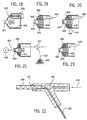
- Figs. 17-20 show various insulation installation methods.
- a cylindrical metal liner 400 is inserted into pot 402 and welded thereto by a welding gun 404, Fig. 18.
- This liner is shown in various of the above figures, for example at 406, 408 in Fig. 1, 410, 412, 414 in Fig. 4, 416 in Fig. 5, 418 in Fig. 6.
- a preformed annular insulation cartridge 420 is inserted into pot 402 through open end 422.
- Cartridge 420 is axially slid along pipe 424 into engagement with dome head 426, Fig. 19.
- Annular disc or plate 428 is then inserted and welded to pipe 424 by weld gun 430.
- This insulation package is also shown in Figs. 5 and 6.
- annular disc like cartridges or donuts 432, 434, 436, etc., Fig. 17, are serially inserted one after the other into pot 402, with or without liner 400, through open end 422, and axially slid along pipe 424 to form a stack of donuts, Fig. 20, circumferentially surrounding the pipe, followed by insertion and welding of plate 428 as above.
- the donuts have different shape.
- Annular donut 432 has a central aperture 438 for receiving pipe 424, a first domed arcuate side 440 conforming to dome head 426, and a second flat side 442.
- Second annular donut 434 has a central aperture 444 for receiving pipe 424, a first flat side 446 for mating against flat side 442 of donut 432, and a second flat side 448. Further donuts as desired, such as 436, each have a central aperture 450 for receiving pipe 424, a first flat side 452 for mating against the preceding donut such as 434, and a second flat side 454 for mating against the succeeding donut.
- Pipe 424 is inserted through dome head 426 prior to insertion of the donuts into pot 402.
- First donut 432 is inserted into pot 402, and the aperture 438 of donut 432 is slid along pipe 424 until domed arcuate side 440 of donut 432 engages dome head 426.
- Second donut 434 is inserted into pot 402, and aperture 444 of donut 434 is slid along pipe 424 until flat side 446 of donut 434 engages flat side 442 of donut 432.
- the next donut such as 436 is inserted into pot 402, and aperture 450 of such donut is slid along pipe 424 until flat side 452 engages flat side 448 of donut 434.
- Donuts are continued to be inserted into the pot along pipe 424 to a desired length to provide a plurality of serially stacked donuts along pipe 424 within pot 402.
- the donuts are stacked such that each interface between successive donuts defines a plane substantially perpendicular to the axial extension of pipe 424.
- the donuts 432, 434, 436, etc., Figs. 17 and 20 are provided of differing sound absorption characteristics to provide differing sound absorption across the respective interfaces between donuts such that there is an impedance change at the interface which causes a reactive effect in addition to a resistive effect. In preferred form, this is accomplished by providing different density donuts.
- the series of donuts providing a series of different sound absorption characteristics provide a plurality of interfaces alternating between increasing and decreasing impedance change thereacross, e.g. providing alternate high and low density, donuts in series.
- Figs. 21-23 show a further insulation installation technique.
- a spool 460 of continuous filament insulation thread 462 is fed into pot 402 around pipe 424. Thread 462 is drawn from spool 460 and air blown by air nozzle 461 of air gun 464 into pot 402 with or without liner 400.
- the thread is preferably multi-stranded yarn. Pressurized air is supplied at 466 to the air gun and puffs out the strands of the thread as shown at 468 during blowing into pot 402.
- Continuous filament thread for insulation is known in the prior art In the present implementation, the continuous filament is desirable because it eliminates fiber ends which are believed to contribute to deterioration of silencer insulation because the ends tend to disintegrate over time and in response to heat.
- vacuum is applied to the pot at 463 from vacuum source 465 to apply vacuum to pot 402 through the perforations 467 in the interior portion of pipe 424 during blowing of thread 462 into pot 402 by air gun 464.
- the vacuum draws and locates the thread into the pot.
- plate 428 is inserted and welded as before.
- the described blown-in insulation installation technique is particularly desirable from a commercial and manufacturing standpoint because of the modularity-enhancing characteristics thereof complementing the modularity of the pots and further simplifying construction, reducing part content, and reducing labor cost by providing a less labor intensive manufacturing process and assembly sequence.
- the technique provides not only the noted commercial and manufacturing advantages, but also improved performance in extended life due to reduction of deterioration and disintegration of insulation.
- Fig. 26 shows a modular silencer component 480 including first and second axially aligned drawn pots 482, 484, each having an axially extending continuous sidewall open at one axial end and having an integral dome head at the other axial end.
- Pot 482 is within pot 484, to provide a lined double-walled member having a double-walled dome head 486 and a double-walled sidewall 488.
- Dome head 490 of pot 484 engages dome head 492 of pot 482 in conforming coextensive parallel arcuate relation.
- Sidewall 494 of pot 484 engages sidewall 496 of pot 482 in conforming parallel concentric relation. Pot 482 is axially inserted fully into pot 484 until dome head 492 of pot 482 engages dome head 490 of pot 484.
- Fig. 27 shows a modular plug silencer 502 including an outer pot assembly 503 including axially aligned drawn outer pots 504, 506, 508, each having an axially extending continuous sidewall open at one axial end and having an integral dome head at the other axial end.
- Inlet pipe 510 extends axially through dome head 512 of pot 504.
- Outlet pipe 514 extends axially through dome head 516 of pot 508.
- a smaller inner drawn pot 518 is within the outer pot assembly and diverts fluid flow from inlet pipe 510 laterally around inner pot 518 as shown at arrows 520, 522.
- Inner drawn pot 518 has an integral dome head 524, and an axially extending continuous sidewall 526 along which fluid flows axially.
- Dome head 528 of outer pot 506 provides a dividing wall extending laterally inwardly from the outer pot assembly and supporting inner pot 518 which extends axially through a central aperture 529 in dome head 528. Dome head 528 is perforated, as at 530, 532, to pass fluid flow axially therethrough after being laterally diverted by inner pot 518. Cylindrical sidewall 526 of inner pot 518 is open at the leftward axial end 534 in Fig. 27, and has integral dome head 524 at the rightward axial end. Open axial end 534 of inner pot 518 faces inlet pipe 510.
- Cylindrical sidewall 526 of inner pot 518 extends from dome head 524 toward open end 534 along an axial direction opposite to the axial direction of fluid flow.
- Inner pot 518 is mounted between inlet pipe 510 at open end 534 of the inner pot, preferably by welding, and dome head 528 of outer pot 506 at dome head 524 of inner pot 518, preferably by welding.
- Inlet pipe 510 extends rightwardly through dome head 512 all the way to open end 534 of inner pot 518, and the portion of inlet exhaust pipe 510 between dome head 512 and inner pot 518 is perforated as shown at 511.
- inlet pipe 510 may extend only partially toward pot 518, and there may be an axial gap between such inlet pipe and the open end 534 of inner pot 518.
- cylindrical sidewall 526 of inner pot 518 may extend leftwardly through dome head 512 of pot 504, to provide the inlet pipe, to be described, Fig. 39.
- inner pot 518 is within outer pot assembly 503 and is spaced laterally inwardly of sidewall 505 of outer pot 504 by a lateral gap 507 permitting fluid flow axially through such gap as shown at arrows 520a and 522a.
- Inner pot 518 is axially spaced from dome head 512 of outer pot 504 by an axial gap 509 permitting fluid flow laterally through such axial gap as shown at arrows 520b and 522b.
- Dome head 226 of inner pot 204 is spaced axially from dome head 224 of outer pot 202 by axial gap 225.
- Dome head 232 of inner pot 208 is axially spaced from dome head 230 of outer pot 206 by axial gap 231.
- Inner pots 204 and 208 are coaxially aligned, and lateral gap 215 defines an annulus through which fluid flows.
- Annulus 215 has an outer circumference at sidewalls 203 and 207 of outer pots 202 and 206.
- Annulus 215 has an inner circumference at sidewalls 220 and 240 of inner pots 204 and 208.
- pot 518 is within outer pot 504, and sidewall 526 of inner pot 518 is spaced laterally inwardly of sidewall 505 of outer pot 504 by lateral gap 507 permitting fluid flow axially, at arrows 520a, 522a, through such lateral gap 507.
- Dome head 524 of inner pot 518 is spaced axially from dome head 512 of outer pot 504 by axial gap 509 permitting fluid flow laterally, at arrows 520b, 522b, through such axial gap 509.
- Pots 504 and 518 are coaxially aligned, and lateral gap 507 defines an annulus through which fluid flows axially.
- Annulus 507 has an outer circumference at sidewall 505 of outer pot 504.
- Annulus 507 has an inner circumference at sidewall 526 of inner pot 518.
- Fig. 28 shows a modular plug silencer 540 including an outer pot assembly 541 including axially aligned drawn outer pots 542, 544, 546, each having an axially extending continuous sidewall open at one axial end and having an integral dome head at the other axial end.
- Inlet pipe 548 extends axially through dome head 550 of pot 542.
- Outlet pipe 552 extends axially through dome head 554 of pot 546.
- Inner drawn pot 556 is within the outer pot assembly and has an axially extending continuous sidewall 558 open at its rightward axial end and has an integral dome head 560 at its leftward axial end.
- Inner pot 556 diverts fluid flow from inlet pipe 548 laterally around the inner pot as shown at arrows 562, 564.
- Dome head 566 of outer pot 544 provides a divider wall extending laterally inwardly from the outer pot assembly and supporting inner pot 556. Dome head 566 is perforated, as at 568, 570, and passes fluid flow axially therethrough after being laterally diverted by inner pot 556. Cylindrical sidewall 558 of inner pot 556 extends from dome head 560 toward the rightward open end of the pot along an axial direction the same as the axial direction of fluid flow. In the embodiment in Fig. 28, inner pot 556 is within inlet pipe 548. Dome head 566 of outer pot 544 has a central aperture at 567 receiving pipe 548. The interior portion of pipe 548 is perforated, as at 549.
- Dome head 566 at aperture 567 is welded around pipe 548, and inner pot 556 is welded within pipe 548.
- a singular through pipe 572 extends through all of the outer pots, including through dome heads 550, 566, 554 of pots 542, 544, 546, respectively, such that the singular through pipe 572 provides both the inlet pipe 548 and the outlet pipe 552.
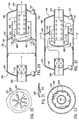
- Fig. 29 shows a modular spark arrestor silencer 580 including an outer pot assembly 581 including axially aligned drawn pots 582, 584, 586, each having an axially extending continuous sidewall open at one axial end and having an integral dome head at the other axial end.
- Inlet pipe 588 extends axially through dome head 590 of pot 582.
- Outlet pipe 592 extends axially through dome head 594 of pot 586.
- Spin flow structure 596 is provided within the outer pot assembly and imparts a spinning corkscrew motion as shown at 598 to fluid flow from inlet pipe 588 before passage to outlet pipe 592.
- the spin flow structure includes a plurality of louvers 600 receiving axial fluid flow from inlet pipe 588 and imparting a radial and circumferential component thereto.
- Dome head 602 of outer pot 584 provides an annular divider wall extending laterally inwardly from the outer pot assembly and supporting the louvers. Dome head 602 directs fluid flow from inlet pipe 588 to the louvers, and blocks reverse fluid flow after passage through the louvers.
- the spin flow structure is provided by an inner drawn pot 604 within the outer pot assembly.
- Inner pot 604 has a continuous cylindrical sidewall 606 open at its rightward axial end, and an integral dome head 608 at its leftward axial end.
- Inner pot 604 extends through central aperture 603 in dome head 602 of outer pot 584, and is mounted thereto by welding.
- Dome head 608 of inner pot 604 has a plurality of louvers 600 punched therethrough, Figs. 29-31.
- the louvers receive axial fluid flow from inlet pipe 588 and impart the noted radial and circumferential component thereto.
- Dome head 608 axially faces inlet pipe 588, and cylindrical sidewall 606 of inner pot 604 extends axially from dome head 608 to the rightward open axial end of the inner pot along the same axial direction as fluid flow.
- louvers 600 as shown at arrow 598 carries spark debris into inner pot 604 along cylindrical sidewall 606 and through the rightward open end of inner pot 604 into outer pot 586 for collection along cylindrical sidewall 610 thereof, and subsequent clean-out for example at clean-out plug 612.
- Figs. 32 and 33 show an alternate example of the structure of Figs. 29-31, and use like reference numerals where appropriate to facilitate understanding.
- louvers 605 instead are punched through sidewall 606 of inner pot 604, to impart a radial and circumferential component to the fluid flow, and provide the noted spinning corkscrew motion to carry spark debris into inner pot 604 along cylindrical sidewall 606 and through the rightward open end of the inner pot into outer pot 586 for collection and clean-out, as above.
- Fig. 34 shows a modular aspirating silencer 620 including a pot assembly 621 including axially aligned drawn pots 622, 624, 626, each having an axially extending continuous sidewall open at one axial end and having an integral dome head at the other axial end.
- Inlet pipe 628 extends axially through dome head 630 of pot 622.
- Outlet pipe 632 extends axially through dome head 634 of pot 626.
- a converging cone 636 within the pots provides a venturi 638.
- An aspiration inlet 640 into the pot assembly aspirates venturi 638.
- Dome head 642 of pot 624 has an opening punched therethrough along a frustoconically tapered sidewall 644 providing the converging cone.
- the aspiration inlet includes an aspiration pipe 646 extending through dome head 642 of pot 624.
- Frustoconically tapered sidewall 644 tapers from an upstream diameter to a smaller downstream diameter.
- Outlet exhaust pipe 632 is axially aligned with convergence cone 636 and has a larger diameter than the noted downstream diameter of frustoconically tapered sidewall 644.
- Fig. 35 shows a modular catalytic silencer 650 including a pot assembly 651 including axially aligned drawn pots 652, 654, each having an axially extending continuous sidewall open at one axial end and having an integral dome head at the other axial end.
- Inlet pipe 656 extends axially through dome head 658 of pot 652.
- Outlet pipe 660 extends axially through dome head 662 of pot 654.
- Catalytic media 664 is provided in at least one of the pots, either in the form of a known catalytic monolith or known catalytic beads.
- Fig. 36 shows a modular catalytic silencer 670 including a pot assembly 671 including axially aligned drawn pots 672, 674, 676, each having an axially extending continuous sidewall open at one axial end and having an integral dome head at the other axial end.
- Inlet pipe 678 extends axially through dome head 680 of pot 672.
- Outlet pipe 682 extends axially through dome head 684 of pot 676.
- Dome head 686 of pot 674 is at the open end of pot 676.
- Catalytic media 688 is in pot 676.
- Dome head 686 of pot 674 has a plurality of laterally spaced openings or perforations 690 therethrough for fluid flow distribution to catalytic media 688 in pot 676.
- Fig. 37 shows a modular catalytic silencer 702 including a pot assembly 703 including axially aligned drawn pots 704, 706, 708, 710, each having an axially extending continuous sidewall open at one axial end and having an integral dome head at the other axial end.
- Inlet pipe 712 extends axially through dome head 714 of pot 704.
- Outlet pipe 716 extends axially through dome head 718 of pot 710.
- Dome head 720 of pot 706 is at the open end of pot 708.
- Dome head 722 of pot 708 is at the open end of pot 710.
- Catalytic media 724 is in pot 708.
- Dome head 720 of pot 706 has a plurality of laterally spaced openings or perforations 726 therethrough for fluid flow distribution to catalytic media 724 in pot 708.
- Dome head 722 has a plurality of laterally spaced openings or perforations 728 therethrough for fluid flow distribution from catalytic media 724 in pot 708.
- Fig. 38 shows a modular heat transfer silencer 740 including a pot assembly 741 including axially aligned drawn pots 742, 744, each having an axially extending continuous sidewall open at one axial end and having an integral dome head at the other axial end.
- Inlet pipe 746 extends axially through dome head 748 of pot 742.
- Outlet pipe 750 extends axially through dome head 752 of pot 744.
- Fluid heat exchanger module 754 in the pot assembly has a heat exchanger inlet 756 extending through the pot assembly into heat exchanger 754, and a heat exchanger outlet 758 extending out of the heat exchanger 754 through the pot assembly, to transfer heat between fluid in the pots and fluid in heat exchanger 754.
- heat exchanger 754 is a heat recovery module recovering heat from the pot assembly and delivering fluid at heat exchanger outlet 758 at an elevated temperature relative to fluid at heat exchanger inlet 756.
- Fig. 39 shows a silencer 770 similar to silencer 502 in Fig. 27, and uses like reference numerals where appropriate to facilitate understanding.
- Outer pot assembly 772 includes outer pots 506 and 508, as in Fig. 27, and includes a pot 774 with cylindrical sidewall 776 and integral dome head 778.
- Inner pot 780 includes cylindrical sidewall 782 open at its leftward axial end and having integral dome head 784 at its other axial end.
- cylindrical sidewall 782 of inner pot 780 provides inlet pipe 786.
- Cylindrical sidewall 782 of inner pot 780 extends from dome head 784 of the inner pot axially leftwardly in Fig. 39 toward the open end of the inner pot axially through dome head 778 of outer pot 774. This eliminates separate inlet pipe 510 in Fig. 27.
- numerous other combinations of structures and chambers may be mixed and matched.
- numerous of the joints or interfaces between the pots may be provided by direct welding of the pots to each other and/or the addition of flange joints at such interfaces which may be welded and/or bolted, the latter facilitating disassembly or removal for clean-out, or the like.
- Such flange joints can be provided by an annular disc or ring around the pot, or could be provided, for example, by flaring the open end of the pot outwardly to a larger radius.
- the present invention may be used in combination with conventional silencers, for example by adding pots or chambers on either end of a conventional silencer.
- the present silencer may be used as a complete stand alone unit, or, for example, may be enclosed within a conventional silencer, or may be provided around and encompassing a conventional silencer.
Landscapes
- Engineering & Computer Science (AREA)
- Chemical & Material Sciences (AREA)
- Combustion & Propulsion (AREA)
- Mechanical Engineering (AREA)
- General Engineering & Computer Science (AREA)
- Chemical Kinetics & Catalysis (AREA)
- Health & Medical Sciences (AREA)
- Toxicology (AREA)
- Exhaust Silencers (AREA)
Description
- The invention relates to silencers, and more particularly to economical silencer constructions, components, and methods.
- Silencers are used in various applications for quieting noise, including mufflers for internal combustion engines, and including other devices such as rotary blowers, compressors, pumps, and the like. Silencers may be used on intake and/or exhaust systems, and may pass various intake and/or exhaust fluids therethrough, including gas and liquid.
- Silencers are typically characterized by complex constructions and labor intensive manufacturing methods, particularly welding, all contributing to high cost. The present invention provides simplified constructions and methods in combination with a modular building block approach, to lower cost. The invention also provides simplified, cost effective insulation techniques.
- US 5,020,631 discloses a silencer having a case formed from first and second case elements with an axial tube through both case elements. A third case element may also be provided.
- The present invention provides a modular silencer as set out in claim 1.
- The invention also provides a method for making a modular silencer as set out in claim 5.
- Preferred features are set out in the dependent claims.
- Fig. 1 is a sectional view of a silencer constructed in accordance with the invention.
- Fig. 2 is a sectional view taken along line 2-2 of Fig. 1.
- Fig. 3 is a view of a portion of the structure of Fig. 1 and shows a further embodiment.
- Fig. 4 is a sectional view of a silencer constructed in accordance with the invention.
- Fig. 5 is a sectional view of a silencer constructed in accordance with the invention.
- Fig. 6 is a sectional view of a silencer constructed in accordance with the invention.
- Fig. 7 is a sectional view taken along line 7-7 of Fig. 6.
- Fig. 8 is a sectional view of a silencer.
- Fig. 9 is a sectional view of a silencer.
- Fig. 10 is a sectional view of a silencer constructed in accordance with the invention.
- Figs. 11-20 sequentially illustrate manufacturing steps for constructing a silencer component.
- Figs. 21-23 sequentially illustrate an insulation technique.
- Fig. 24 is an exploded perspective view of the structure of Fig. 1.
- Fig. 25 is an assembled perspective view of the structure of Fig. 1.
- Fig. 26 is a sectional view of a silencer component.
- Fig. 27 is a sectional view of a plug silencer.
- Fig. 28 is like Fig. 27 and shows a further example.
- Fig. 29 is a sectional view of a spark arrestor silencer,
- Fig. 30 is a sectional view taken along line 30-30 of Fig. 29.
- Fig. 31 is a sectional view taken along line 31-31 of Fig. 30.
- Fig. 32 is a sectional view of a spark arrestor silencer constructed in accordance with the invention.
- Fig. 33 is a sectional view taken along line 33-33 of Fig. 32.
- Fig. 34 is a sectional view of an aspirating silencer.
- Fig. 35 is a sectional view of a catalytic silencer.
- Fig. 36 is like Fig. 35 and shows a further example.
- Fig. 37 is like Fig. 35 and shows a further example.
- Fig. 38 is a sectional view of a heat recovery silencer.
- Fig. 39 is a sectional view of a silencer.
- Fig. 1 shows a modular silencer or
muffler 30 constructed in accordance with an embodiment of the invention, including a plurality of axially aligned drawn pots. Draw forming of pots is known in the prior art, for example as shown in US Patent 5,020,631,
and is briefly illustrated in Figs. 11 and 12. A flat sheet ofmetal 32, Fig. 11, is gradually and repetitively deformed and cold flowed by a mandrel to a pot or can 34 as shown in Fig. 12. The pot is trimmed to a desired length byknife blade 36, Fig. 13.Pot 34 has an axially extendingcontinuous sidewall 38 open at oneend 40 and having anintegral dome head 42 at the other axial end. Fig. 1 shows first, second and third axially aligned drawnpots Pot 48 is formed as above described and then further by punching a hole through its dome head withpunch 50, Fig. 15, and then inserting apipe 52, Fig. 16, through such hole and welding the pipe to the dome head of the pot bywelding gun 54.Pot 46, Fig. 1, is similarly made, except that the hole in the dome head is punched at a location laterally offset from the axial centerline, for example as shown at the middle pot in Fig. 24.Pot 44 is similarly constructed aspot 48, except that an additional step, Fig. 14, is provided wherein a tool 56 swages, necks or joggles the open end of the pot to a reduced diameter at 58. The swaging enables telescoped nesting engagement ofpots pot 46 is swaged at its open end rather thanpot 44, to provide the telescoped nesting engagement. - The construction in Fig. 1 includes first and second axially aligned drawn
pots Pot 44 has an axially extendingcontinuous sidewall 60 initially open ataxial end 62 and having anintegral dome head 64 at the other axial end.Pot 46 has an axially extendingcontinuous sidewall 66 initially open ataxial end 68 and having anintegral dome head 70 at the other axial end.Inlet pipe 72 extends axially throughdome head 64 along the axial centerline of the pots. In an alternate embodiment,inlet pipe 72 extends axially throughdome head 64 and is laterally offset from the axial centerline of the pots. In another alternate embodiment,inlet pipe 72 extends throughdome head 64 at an angle relative to the axial centerline of the pots, for example 30° or some other angle. In the latter embodiment, the inlet pipe intersects the dome head at a point laterally offset from the axial centerline of the pots. Intermediate connectingpipe 74 extends axially throughdome head 70 and is laterally offset from the axial centerline of the pots, Figs. 1 and 2. The construction of Fig. 1 further includes a third axially aligned drawnpot 48 having an axially extendingcontinuous sidewall 76 initially open ataxial end 78 and having anintegral dome head 80 at the other axial end.Outlet pipe 82 extends axially throughdome head 80 along the axial centerline of the pots. In alternate embodiments,pipe 82 may be laterally offset from the axial centerline of the pots, or may extend at an angle relative to such centerline, as above described in conjunction withpipe 72. The pots are welded together bycircumferential weldments welder 88, Fig. 25. Further in Fig. 1,dome head 64 has another hole punched therethrough, with asleeve 90 inserted therein and welded thereto atweldment 91 and receiving adrain plug 92 in threaded relation.Pipe 74 has a plurality of perforations such as 75 through the sidewall thereof.Pipes pipes - In Fig. 1,
pipe 74 is laterally offset frompipe 72 and is laterally offset frompipe 82.Pipes path 94, then reverses itself and flows axially in the opposite direction alongpath 96 laterallyadjacent path 94, and then reverses itself again and flows axially rightwardly alongpath 98 laterallyadjacent paths Path 94 is throughpipe 74 throughdome head 70.Path 98 is throughpipe 82 throughdome head 80.Pipes axial ends axial end 100 ofpipe 72 toaxial end 102 ofpipe 74 without reversing itself.Pipes pipe 74. - Fig. 3 shows a further embodiment of the construction of Fig. 1.
Flanges respective pipes - Fig. 4 shows a
silencer 110 with first, second, third and fourth axially aligned drawnpots Inlet pipe 120 extends axially throughdome head 122 ofpot 112 along the axial centerline thereof. Intermediate connectingpipe 124 extends axially throughdome head 126 ofpot 114 along the axial centerline thereof. Intermediate connectingpipe 128 extends axially throughdome head 130 ofpot 116 and is laterally offset from the axial centerline of the pots.Outlet pipe 132 extends axially throughdome head 134 ofpot 118 along the axial centerline thereof. Axial ends 136 and 138 ofrespective pipes - Fig. 5 shows a
silencer 140 having first, second and third axially aligned drawnpots Inlet pipe 148 extends axially throughdome head 150 ofpot 142 along the axial centerline thereof, and throughinsulation 152, to be described. Intermediate connectingpipe 154 extends axially throughdome head 156 ofpot 144 and is laterally offset from the axial centerline of the pots.Outlet pipe 158 extends axially throughdome head 160 ofpot 146 along the axial centerline thereof. In Fig. 5, there is no axial overlapping of the pipes, and the axial ends of all the pipes are axially spaced from each other in nonoverlapping relation. - Fig. 6 shows a
silencer 162 having first, second and third axially aligned drawnpots Inlet pipe 170 extends axially throughdome head 172 ofpot 164 along the axial centerline thereof. A pair of intermediate connectingpipes dome head 178 ofpot 166 and are each laterally offset from the axial centerline of the pots.Pipes cross brace 180 welded therebetween.Outlet pipe 182 extends axially throughdome head 184 ofpot 168 along the axial centerline thereof.Pipes pipes Pipes pipes Pipes axial end 186 axially spaced fromaxial end 188 ofpipe 170 in nonoverlapping relation.Pipes axial end 190 axially spaced fromaxial end 192 ofpipe 182 in nonoverlapping relation. - Fig. 8 shows a
silencer 200 having first, second, third and fourth drawnpots Pot 202 concentrically surroundspot 204.Pot 206 concentrically surroundspot 208.Pots open ends first enclosure 214.Pots open ends 216 and 218 to form asecond enclosure 220 withinenclosure 214.Inlet pipe 222 extends axially throughdome head 224 ofpot 202 and throughdome head 226 ofpot 204 along the axial centerline thereof.Outlet pipe 228 extends axially throughdome head 230 ofpot 206 and throughdome head 232 ofpot 208 along the axial centerline thereof.Pipes enclosure 220 and axially spaced from each other in nonoverlapping relation.Dome head 224 ofpot 202 is axially spaced fromdome head 226 ofpot 204 by anaxial gap 225 which is spanned bypipe 222.Dome head 230 ofpot 206 is axially spaced fromdome head 232 ofpot 208 by anaxial gap 231 which is spanned bypipe 228.Pots sidewalls Pots enclosure 214 are coaxial withpots enclosure 220.Enclosure 220 is spaced radially inwardly ofenclosure 214 by anannular gap 215. - Fig. 9 shows a
silencer 250 including first, second, third and fourth axially aligned drawnpots Pots open ends first compartment 264.Pots open ends second compartment 270. An intermediatecylindrical sidewall 272 extends axially betweenpots cylindrical sidewall 272 has a leftwardaxial end 274 connected to the junction ofcylindrical sidewall 276 anddome head 278 ofpot 254. Intermediatecylindrical sidewall 272 has a rightwardaxial end 280 connected to the junction ofcylindrical sidewall 282 anddome head 284 ofpot 256. The noted connection of intermediatecylindrical sidewall 272 topots third compartment 286.Inlet pipe 288 extends axially throughdome head 290 ofpot 252 along the axial centerline thereof and intocompartment 264.Outlet pipe 292 extends axially throughdome head 294 ofpot 258 along the axial centerline thereof and intocompartment 270. Outlet orinlet pipe 296 extends radially through intermediatecylindrical sidewall 272 and intocompartment 286. Intermediate connectingpipe 298 extends axially throughdome head 278 ofpot 254 and is laterally offset from the axial centerline thereof.Pipe 298 extends betweencompartments pipe 288 incompartment 264. Intermediate connectingpipe 300 extends axially throughdome head 284 ofpot 256 and is laterally offset from the axial centerline thereof.Pipe 300 extends betweencompartments pipe 292 incompartment 270.Pipes compartment 286. - Fig. 10 shows a
silencer 310 including first, second and third axially aligned drawnpots pot 318 has acontinuous sidewall 320 initially open at oneend 322 and having anintegral dome head 324 at the other end.End 322 ofpot 318 is connected to sidewall 326 ofpot 316 and extends laterally away therefrom.Open end 328 ofpot 312 is connected to openend 330 ofpot 314.Open end 332 ofpot 316 is connected to the junction ofsidewall 334 anddome head 336 ofpot 314.Sidewall 320 ofpot 318 is connected to sidewall 326 ofpot 316 along an arcuate interface as shown in dashed line at 338.Outlet pipe 340 extends axially throughdome head 342 ofpot 312 along the axial centerline thereof. Intermediate connectingpipe 344 extends axially throughdome head 336 ofpot 314 and is laterally offset from the axial centerline thereof.Dome head 346 ofpot 316 does not have an inlet pipe therethrough. Intermediate connectingpipe 348 extends laterally throughsidewall 326 ofpot 316.Inlet pipe 350 extends throughdome head 324 ofpot 318. - In various of the examples shown above, a first pot, such as 360, Fig. 14, has a
main body portion 362 of afirst diameter 364, and anopen end portion 366 of a secondsmaller diameter 368. Asecond pot 370, Fig. 15, is not necked by tool 56 and has both itsmain body portion 372 and itsopen end portion 374 of the notedfirst diameter 364. As shown above, such pots are axially overlapped in nesting telescoped relation, for example as shown at ends 62 and 68 in Fig. 1, ends 210 and 212, and 216 and 218, in Fig. 8, ends 260 and 262, and 266 and 268, in Fig. 9, ends 330 and 328 in Fig. 10, and in other figures.Sidewall 362; Fig. 14, ofpot 360 has atransition portion 376 betweenmain body portion 362 andopen end portion 366. Whenpots open end 374 ofpot 370 axially facestransition portion 376 ofpot 360, for example as shown in Fig. 1 atend 68 ofsidewall 66 ofpot 46 axially facingtransition portion 378 ofsidewall 60 ofpot 44 and connected thereto byweldment 84 at such interface.Sidewall 362, Fig. 14, ofpot 360 meetsdome head 380 ofpot 360 at ajunction 382, which junction is circumferential and is of thenoted diameter 364.Sidewall 372 ofpot 370 meetsdome head 384 ofpot 370 atjunction 386, which junction is circumferential and has the noteddiameter 364. This is desirable for various of the above shown mounting arrangements wherein the open end of a pot meets and is joined to the closed dome head end of another pot, for example as shown in Fig. 1 whereopen end 78 ofsidewall 76 ofpot 48 abuts thejunction 388 ofsidewall 66 anddome head 70 ofpot 46 and is connected thereto atweldment 86 at such interface. The difference betweendiameters sidewall 372 ofpot 370, to enable a flush fit outer axially extending surface after assembly. - Figs. 17-20 show various insulation installation methods. In one example, a
cylindrical metal liner 400 is inserted intopot 402 and welded thereto by awelding gun 404, Fig. 18. This liner is shown in various of the above figures, for example at 406, 408 in Fig. 1, 410, 412, 414 in Fig. 4, 416 in Fig. 5, 418 in Fig. 6. In another example, with or withoutliner 400, a preformedannular insulation cartridge 420, Fig. 17, is inserted intopot 402 throughopen end 422.Cartridge 420 is axially slid alongpipe 424 into engagement withdome head 426, Fig. 19. Annular disc orplate 428 is then inserted and welded topipe 424 byweld gun 430. This insulation package is also shown in Figs. 5 and 6. - In an alternate example, a plurality of annular disc like cartridges or
donuts pot 402, with or withoutliner 400, throughopen end 422, and axially slid alongpipe 424 to form a stack of donuts, Fig. 20, circumferentially surrounding the pipe, followed by insertion and welding ofplate 428 as above. The donuts have different shape.Annular donut 432 has acentral aperture 438 for receivingpipe 424, a first domedarcuate side 440 conforming todome head 426, and a secondflat side 442. Secondannular donut 434 has acentral aperture 444 for receivingpipe 424, a firstflat side 446 for mating againstflat side 442 ofdonut 432, and a secondflat side 448. Further donuts as desired, such as 436, each have acentral aperture 450 for receivingpipe 424, a firstflat side 452 for mating against the preceding donut such as 434, and a secondflat side 454 for mating against the succeeding donut.Pipe 424 is inserted throughdome head 426 prior to insertion of the donuts intopot 402.First donut 432 is inserted intopot 402, and theaperture 438 ofdonut 432 is slid alongpipe 424 until domedarcuate side 440 ofdonut 432 engagesdome head 426.Second donut 434 is inserted intopot 402, andaperture 444 ofdonut 434 is slid alongpipe 424 untilflat side 446 ofdonut 434 engagesflat side 442 ofdonut 432. The next donut such as 436 is inserted intopot 402, andaperture 450 of such donut is slid alongpipe 424 untilflat side 452 engagesflat side 448 ofdonut 434. Donuts are continued to be inserted into the pot alongpipe 424 to a desired length to provide a plurality of serially stacked donuts alongpipe 424 withinpot 402. The donuts are stacked such that each interface between successive donuts defines a plane substantially perpendicular to the axial extension ofpipe 424. - In a further example, the
donuts - Figs. 21-23 show a further insulation installation technique. A
spool 460 of continuousfilament insulation thread 462 is fed intopot 402 aroundpipe 424.Thread 462 is drawn fromspool 460 and air blown byair nozzle 461 ofair gun 464 intopot 402 with or withoutliner 400. The thread is preferably multi-stranded yarn. Pressurized air is supplied at 466 to the air gun and puffs out the strands of the thread as shown at 468 during blowing intopot 402. Continuous filament thread for insulation is known in the prior art In the present implementation, the continuous filament is desirable because it eliminates fiber ends which are believed to contribute to deterioration of silencer insulation because the ends tend to disintegrate over time and in response to heat. In one embodiment, vacuum is applied to the pot at 463 fromvacuum source 465 to apply vacuum topot 402 through theperforations 467 in the interior portion ofpipe 424 during blowing ofthread 462 intopot 402 byair gun 464. The vacuum draws and locates the thread into the pot. After the insulation thread is blown into the pot as shown at 470, Fig. 23,plate 428 is inserted and welded as before. The described blown-in insulation installation technique is particularly desirable from a commercial and manufacturing standpoint because of the modularity-enhancing characteristics thereof complementing the modularity of the pots and further simplifying construction, reducing part content, and reducing labor cost by providing a less labor intensive manufacturing process and assembly sequence. The technique provides not only the noted commercial and manufacturing advantages, but also improved performance in extended life due to reduction of deterioration and disintegration of insulation. - Fig. 26 shows a
modular silencer component 480 including first and second axially aligned drawnpots Pot 482 is withinpot 484, to provide a lined double-walled member having a double-walled dome head 486 and a double-walled sidewall 488.Dome head 490 ofpot 484 engagesdome head 492 ofpot 482 in conforming coextensive parallel arcuate relation.Sidewall 494 ofpot 484 engagessidewall 496 ofpot 482 in conforming parallel concentric relation.Pot 482 is axially inserted fully intopot 484 untildome head 492 ofpot 482 engagesdome head 490 ofpot 484. - Fig. 27 shows a
modular plug silencer 502 including anouter pot assembly 503 including axially aligned drawnouter pots Inlet pipe 510 extends axially throughdome head 512 ofpot 504.Outlet pipe 514 extends axially throughdome head 516 ofpot 508. A smaller inner drawnpot 518 is within the outer pot assembly and diverts fluid flow frominlet pipe 510 laterally aroundinner pot 518 as shown atarrows drawn pot 518 has anintegral dome head 524, and an axially extendingcontinuous sidewall 526 along which fluid flows axially.Dome head 528 ofouter pot 506 provides a dividing wall extending laterally inwardly from the outer pot assembly and supportinginner pot 518 which extends axially through acentral aperture 529 indome head 528.Dome head 528 is perforated, as at 530, 532, to pass fluid flow axially therethrough after being laterally diverted byinner pot 518.Cylindrical sidewall 526 ofinner pot 518 is open at the leftwardaxial end 534 in Fig. 27, and hasintegral dome head 524 at the rightward axial end. Openaxial end 534 ofinner pot 518 facesinlet pipe 510.Cylindrical sidewall 526 ofinner pot 518 extends fromdome head 524 towardopen end 534 along an axial direction opposite to the axial direction of fluid flow.Inner pot 518 is mounted betweeninlet pipe 510 atopen end 534 of the inner pot, preferably by welding, anddome head 528 ofouter pot 506 atdome head 524 ofinner pot 518, preferably by welding.Inlet pipe 510 extends rightwardly throughdome head 512 all the way to openend 534 ofinner pot 518, and the portion ofinlet exhaust pipe 510 betweendome head 512 andinner pot 518 is perforated as shown at 511. In another embodiment,inlet pipe 510 may extend only partially towardpot 518, and there may be an axial gap between such inlet pipe and theopen end 534 ofinner pot 518. In another embodiment,cylindrical sidewall 526 ofinner pot 518 may extend leftwardly throughdome head 512 ofpot 504, to provide the inlet pipe, to be described, Fig. 39. - In Fig. 27,
inner pot 518 is withinouter pot assembly 503 and is spaced laterally inwardly ofsidewall 505 ofouter pot 504 by alateral gap 507 permitting fluid flow axially through such gap as shown atarrows Inner pot 518 is axially spaced fromdome head 512 ofouter pot 504 by anaxial gap 509 permitting fluid flow laterally through such axial gap as shown atarrows sidewalls inner pots sidewalls outer pots lateral gap 215.Dome head 226 ofinner pot 204 is spaced axially fromdome head 224 ofouter pot 202 byaxial gap 225.Dome head 232 ofinner pot 208 is axially spaced fromdome head 230 ofouter pot 206 byaxial gap 231.Inner pots lateral gap 215 defines an annulus through which fluid flows.Annulus 215 has an outer circumference atsidewalls outer pots Annulus 215 has an inner circumference atsidewalls inner pots pot 518 is withinouter pot 504, andsidewall 526 ofinner pot 518 is spaced laterally inwardly ofsidewall 505 ofouter pot 504 bylateral gap 507 permitting fluid flow axially, atarrows lateral gap 507.Dome head 524 ofinner pot 518 is spaced axially fromdome head 512 ofouter pot 504 byaxial gap 509 permitting fluid flow laterally, atarrows axial gap 509.Pots lateral gap 507 defines an annulus through which fluid flows axially.Annulus 507 has an outer circumference atsidewall 505 ofouter pot 504.Annulus 507 has an inner circumference atsidewall 526 ofinner pot 518. - Fig. 28 shows a
modular plug silencer 540 including anouter pot assembly 541 including axially aligned drawnouter pots Inlet pipe 548 extends axially throughdome head 550 ofpot 542.Outlet pipe 552 extends axially throughdome head 554 ofpot 546. Innerdrawn pot 556 is within the outer pot assembly and has an axially extendingcontinuous sidewall 558 open at its rightward axial end and has anintegral dome head 560 at its leftward axial end.Inner pot 556 diverts fluid flow frominlet pipe 548 laterally around the inner pot as shown atarrows Dome head 566 ofouter pot 544 provides a divider wall extending laterally inwardly from the outer pot assembly and supportinginner pot 556.Dome head 566 is perforated, as at 568, 570, and passes fluid flow axially therethrough after being laterally diverted byinner pot 556.Cylindrical sidewall 558 ofinner pot 556 extends fromdome head 560 toward the rightward open end of the pot along an axial direction the same as the axial direction of fluid flow. In the embodiment in Fig. 28,inner pot 556 is withininlet pipe 548.Dome head 566 ofouter pot 544 has a central aperture at 567 receivingpipe 548. The interior portion ofpipe 548 is perforated, as at 549.Dome head 566 ataperture 567 is welded aroundpipe 548, andinner pot 556 is welded withinpipe 548. In the example of Fig. 28, a singular throughpipe 572 extends through all of the outer pots, including through dome heads 550, 566, 554 ofpots pipe 572 provides both theinlet pipe 548 and theoutlet pipe 552. - Fig. 29 shows a modular
spark arrestor silencer 580 including anouter pot assembly 581 including axially aligned drawnpots Inlet pipe 588 extends axially throughdome head 590 ofpot 582.Outlet pipe 592 extends axially throughdome head 594 ofpot 586. Spin flow structure 596 is provided within the outer pot assembly and imparts a spinning corkscrew motion as shown at 598 to fluid flow frominlet pipe 588 before passage tooutlet pipe 592. The spin flow structure includes a plurality oflouvers 600 receiving axial fluid flow frominlet pipe 588 and imparting a radial and circumferential component thereto.Dome head 602 ofouter pot 584 provides an annular divider wall extending laterally inwardly from the outer pot assembly and supporting the louvers.Dome head 602 directs fluid flow frominlet pipe 588 to the louvers, and blocks reverse fluid flow after passage through the louvers. The spin flow structure is provided by an innerdrawn pot 604 within the outer pot assembly.Inner pot 604 has a continuouscylindrical sidewall 606 open at its rightward axial end, and anintegral dome head 608 at its leftward axial end.Inner pot 604 extends throughcentral aperture 603 indome head 602 ofouter pot 584, and is mounted thereto by welding.Dome head 608 ofinner pot 604 has a plurality oflouvers 600 punched therethrough, Figs. 29-31. The louvers receive axial fluid flow frominlet pipe 588 and impart the noted radial and circumferential component thereto.Dome head 608 axially facesinlet pipe 588, andcylindrical sidewall 606 ofinner pot 604 extends axially fromdome head 608 to the rightward open axial end of the inner pot along the same axial direction as fluid flow. The spinning corkscrew motion imparted to fluid flow bylouvers 600 as shown atarrow 598 carries spark debris intoinner pot 604 alongcylindrical sidewall 606 and through the rightward open end ofinner pot 604 intoouter pot 586 for collection alongcylindrical sidewall 610 thereof, and subsequent clean-out for example at clean-out plug 612. - Figs. 32 and 33 show an alternate example of the structure of Figs. 29-31, and use like reference numerals where appropriate to facilitate understanding. Instead of punching the louvers through
dome head 608 ofinner pot 604,louvers 605 instead are punched throughsidewall 606 ofinner pot 604, to impart a radial and circumferential component to the fluid flow, and provide the noted spinning corkscrew motion to carry spark debris intoinner pot 604 alongcylindrical sidewall 606 and through the rightward open end of the inner pot intoouter pot 586 for collection and clean-out, as above. - Fig. 34 shows a
modular aspirating silencer 620 including apot assembly 621 including axially aligned drawnpots Inlet pipe 628 extends axially throughdome head 630 ofpot 622.Outlet pipe 632 extends axially throughdome head 634 ofpot 626. A convergingcone 636 within the pots provides aventuri 638. Anaspiration inlet 640 into the pot assembly aspirates venturi 638.Dome head 642 ofpot 624 has an opening punched therethrough along a frustoconically taperedsidewall 644 providing the converging cone. The aspiration inlet includes anaspiration pipe 646 extending throughdome head 642 ofpot 624. Frustoconicallytapered sidewall 644 tapers from an upstream diameter to a smaller downstream diameter.Outlet exhaust pipe 632 is axially aligned withconvergence cone 636 and has a larger diameter than the noted downstream diameter of frustoconicallytapered sidewall 644. - Fig. 35 shows a modular
catalytic silencer 650 including apot assembly 651 including axially aligned drawnpots Inlet pipe 656 extends axially throughdome head 658 ofpot 652.Outlet pipe 660 extends axially throughdome head 662 ofpot 654.Catalytic media 664 is provided in at least one of the pots, either in the form of a known catalytic monolith or known catalytic beads. - Fig. 36 shows a modular
catalytic silencer 670 including apot assembly 671 including axially aligned drawnpots Inlet pipe 678 extends axially through dome head 680 ofpot 672.Outlet pipe 682 extends axially throughdome head 684 ofpot 676.Dome head 686 ofpot 674 is at the open end ofpot 676.Catalytic media 688 is inpot 676.Dome head 686 ofpot 674 has a plurality of laterally spaced openings orperforations 690 therethrough for fluid flow distribution tocatalytic media 688 inpot 676. - Fig. 37 shows a modular
catalytic silencer 702 including apot assembly 703 including axially aligned drawnpots Inlet pipe 712 extends axially throughdome head 714 ofpot 704.Outlet pipe 716 extends axially throughdome head 718 ofpot 710.Dome head 720 ofpot 706 is at the open end ofpot 708.Dome head 722 ofpot 708 is at the open end ofpot 710.Catalytic media 724 is inpot 708.Dome head 720 ofpot 706 has a plurality of laterally spaced openings orperforations 726 therethrough for fluid flow distribution tocatalytic media 724 inpot 708.Dome head 722 has a plurality of laterally spaced openings orperforations 728 therethrough for fluid flow distribution fromcatalytic media 724 inpot 708. - Fig. 38 shows a modular
heat transfer silencer 740 including apot assembly 741 including axially aligned drawnpots Inlet pipe 746 extends axially throughdome head 748 ofpot 742.Outlet pipe 750 extends axially throughdome head 752 ofpot 744. Fluidheat exchanger module 754 in the pot assembly has aheat exchanger inlet 756 extending through the pot assembly intoheat exchanger 754, and aheat exchanger outlet 758 extending out of theheat exchanger 754 through the pot assembly, to transfer heat between fluid in the pots and fluid inheat exchanger 754. In one embodiment,heat exchanger 754 is a heat recovery module recovering heat from the pot assembly and delivering fluid atheat exchanger outlet 758 at an elevated temperature relative to fluid atheat exchanger inlet 756. - Fig. 39 shows a
silencer 770 similar tosilencer 502 in Fig. 27, and uses like reference numerals where appropriate to facilitate understanding.Outer pot assembly 772 includesouter pots pot 774 withcylindrical sidewall 776 andintegral dome head 778.Inner pot 780 includescylindrical sidewall 782 open at its leftward axial end and havingintegral dome head 784 at its other axial end. In Fig. 39,cylindrical sidewall 782 ofinner pot 780 providesinlet pipe 786.Cylindrical sidewall 782 ofinner pot 780 extends fromdome head 784 of the inner pot axially leftwardly in Fig. 39 toward the open end of the inner pot axially throughdome head 778 ofouter pot 774. This eliminatesseparate inlet pipe 510 in Fig. 27. - It is recognized that various equivalents, alternatives and modifications are possible within the scope of the appended claims. In a desirable aspect of the invention, numerous other combinations of structures and chambers may be mixed and matched. In a further desirable aspect, numerous of the joints or interfaces between the pots may be provided by direct welding of the pots to each other and/or the addition of flange joints at such interfaces which may be welded and/or bolted, the latter facilitating disassembly or removal for clean-out, or the like. Such flange joints can be provided by an annular disc or ring around the pot, or could be provided, for example, by flaring the open end of the pot outwardly to a larger radius. The present invention may be used in combination with conventional silencers, for example by adding pots or chambers on either end of a conventional silencer. The present silencer may be used as a complete stand alone unit, or, for example, may be enclosed within a conventional silencer, or may be provided around and encompassing a conventional silencer.
Claims (5)
- A modular silencer (140) for silencing exhaust gas, comprising first, second and third drawn pots (142, 144, 146), each pot having an axially extending continuous sidewall open at one axial end and having an end wall in the form of an integral dome head at the other axial end, said pots being axially aligned, with said open end of said first pot (142) being joined to said open end of said second pot (144), and said dome head (156) of said second pot (144) being joined to said open end of said third pot (146), characterised in that the silencer further comprises first, second and third pipes (148, 154, 158) and extending respectively through said walls of said first, second and third pots (142, 144, 146), said first pipe (148) having an open end terminating in the volume defined by said first and second pots (142, 144), said second pipe (154) having an intermediate section mounted to and extending through said dome head (156) of said second pot (144), said second pipe (154) having a first open end terminating in said volume defined by said first and second pots (142, 144), said second pipe (154) having a second open end terminating in the volume defined by said second and third pots (144, 146), said third pipe (158) having an open end terminating in said volume defined by said second and third pots (144, 146), enabling expansion at said open end of said first pipe (148) into said volume defined by said first and second pots (142, 144) followed by contraction at said first open end of said second pipe (154) followed by expansion at said second open end of said second pipe (154) in said volume defined by said second and third pots (144, 146).
- The modular silencer according to claim 1 wherein said end wall forming said dome head (156) of said second pot (144) is the sole mounting support for said second pipe (154), said second pipe extends (154) as a cantilever from said dome head (156) of said second pot (144) to said first open end of said second pipe as a first free end (154) in said volume defined by said first and second pots (142, 144), and said second pipe (154) extends as a cantilever from said dome head (156) of said second pot (144) to said second open end of said second pipe as a second free end (154) in said volume defined by said second and third pots (144, 146).
- The modular silencer according to claim 1 wherein at least one of said first and third pipes (148, 158) extends through a respective said dome head of the respective said first and third pots (142, 148).
- The modular silencer according to claim 1 wherein at least one of said first and third pipes (148, 158) extends through a respective said side wall of the respective said first and third pots (142, 146).
- A method for making a modular silencer (140) for silencing exhaust gas, comprising draw forming first, second and third pots (142, 144,146), each pot having an axially extending continuous sidewall open at one axial end and having an end wall in the form of an integral dome head at the other axial end, providing first, second and third pipes (148, 154, 158) and extending said pipes respectively through said walls of said first, second and third pots (142, 144, 146), axially aligning said pots, with said open end of said first pot (142) being joined to said open end of said second pot (144), and said dome head (156) of said second pot (144) being joined to said open end of said third pot (146), said first pipe (148) having an open end terminating in the volume defined by said first and second pots (142, 144), said second pipe (154) having an intermediate section mounted to and extending through said dome head (156) of said second pot (144), said second pipe (154) having a first open end terminating in said volume defined by said first and second pots (142, 144), said second pipe (154) having a second open end terminating in the volume defined by said second and third pots (144, 146), said third pipe (158) having an open end terminating in said volume defined by said second and third pots (144, 146), enabling expansion at said open end of said first pipe (148) into said volume defined by said first and second pots (142, 144) followed by contraction at said first open end of said second pipe (154) followed by expansion at said second open end of said second pipe (154) in said volume defined by said second and third pots (144, 146).
Applications Claiming Priority (3)
| Application Number | Priority Date | Filing Date | Title |
|---|---|---|---|
| US88847997A | 1997-07-07 | 1997-07-07 | |
| US888479 | 1997-07-07 | ||
| PCT/US1998/013451 WO1999002826A1 (en) | 1997-07-07 | 1998-06-29 | Modular silencer |
Publications (3)
| Publication Number | Publication Date |
|---|---|
| EP0995018A1 EP0995018A1 (en) | 2000-04-26 |
| EP0995018A4 EP0995018A4 (en) | 2000-07-19 |
| EP0995018B1 true EP0995018B1 (en) | 2002-04-10 |
Family
ID=25393251
Family Applications (1)
| Application Number | Title | Priority Date | Filing Date |
|---|---|---|---|
| EP98932937A Expired - Lifetime EP0995018B1 (en) | 1997-07-07 | 1998-06-29 | Modular silencer |
Country Status (4)
| Country | Link |
|---|---|
| EP (1) | EP0995018B1 (en) |
| AU (1) | AU8271798A (en) |
| DE (1) | DE69804800T2 (en) |
| WO (1) | WO1999002826A1 (en) |
Families Citing this family (17)
| Publication number | Priority date | Publication date | Assignee | Title |
|---|---|---|---|---|
| DK1268989T3 (en) | 2000-03-21 | 2007-01-08 | Silentor Holding As | Attenuators containing one or more porous bodies |
| FR2821574B1 (en) * | 2001-03-02 | 2003-11-28 | Saint Gobain Vetrotex | DEVICE FOR INSERTING INTO A CAVITY OR DEPOSITING FIBERS IN AN EXPANDED FORM ON A SURFACE |
| US6446750B1 (en) * | 2001-03-16 | 2002-09-10 | Owens Corning Fiberglas Technology, Inc. | Process for filling a muffler shell with fibrous material |
| FR2823500B1 (en) * | 2001-04-11 | 2004-02-20 | Saint Gobain Vetrotex | EXPANDED GLASS FIBER PRODUCT AND MANUFACTURING METHOD THEREOF |
| JP2007297985A (en) | 2006-05-01 | 2007-11-15 | Yamaha Motor Co Ltd | Gas exhaust system and vehicle equipped with the gas exhaust system |
| US8590155B2 (en) | 2009-06-03 | 2013-11-26 | Ocv Intellectual Capital, Llc | Apparatus for and process of filling a muffler with fibrous material utilizing a directional jet |
| US8196701B1 (en) | 2010-02-11 | 2012-06-12 | OS Inc. | Acoustic and heat control device |
| US8790434B1 (en) | 2010-02-11 | 2014-07-29 | O.S.S. Holdings, LLC | Particulate capture from a high energy discharge device |
| US8516941B1 (en) | 2010-02-11 | 2013-08-27 | O.S.S. Holdings, LLC | Interchangeable, modular firearm mountable device |
| JP6190603B2 (en) * | 2013-03-18 | 2017-08-30 | 株式会社マキタ | Muffler device and portable work machine |
| CN106640307A (en) * | 2016-12-05 | 2017-05-10 | 济南吉美乐电源技术有限公司 | Internal combustion engine silencer with self-cleaning function |
| CN107636315B (en) * | 2017-03-28 | 2019-05-07 | 美的集团股份有限公司 | Pedestal and bladeless fan |
| US11255623B2 (en) | 2019-04-30 | 2022-02-22 | Sig Sauer, Inc. | Suppressor with reduced gas back flow and integral flash hider |
| US11162753B2 (en) | 2019-05-03 | 2021-11-02 | Sig Sauer, Inc. | Suppressor with integral flash hider and reduced gas back flow |
| US11280571B2 (en) | 2019-12-23 | 2022-03-22 | Sig Sauer, Inc. | Integrated flash hider for small arms suppressors |
| US11686547B2 (en) | 2020-08-12 | 2023-06-27 | Sig Sauer, Inc. | Suppressor with reduced gas back flow |
| US11859932B1 (en) | 2022-06-28 | 2024-01-02 | Sig Sauer, Inc. | Machine gun suppressor |
Family Cites Families (7)
| Publication number | Priority date | Publication date | Assignee | Title |
|---|---|---|---|---|
| US2107588A (en) * | 1937-04-30 | 1938-02-08 | Smith Joseph Leigh | Muffler repair jacket |
| US3827531A (en) * | 1973-08-17 | 1974-08-06 | Nelson Muffler Corp | Exhaust muffler |
| GB1537299A (en) * | 1976-11-12 | 1978-12-29 | Moss L | Exhaust silencers |
| US4102430A (en) * | 1977-08-11 | 1978-07-25 | Tenneco, Inc. | Peripheral return flow muffler |
| CH647302A5 (en) * | 1979-06-06 | 1985-01-15 | Alusuisse | DEVICE FOR DISCHARGING EXHAUST GAS FROM COMBUSTION ENGINES. |
| FR2646207A1 (en) * | 1989-04-25 | 1990-10-26 | Devil | MODULAR MUFFLER |
| JPH07309296A (en) * | 1994-05-19 | 1995-11-28 | Kyoei Seisakusho:Kk | Water lock device for hydro-bicycle |
-
1998
- 1998-06-29 AU AU82717/98A patent/AU8271798A/en not_active Abandoned
- 1998-06-29 WO PCT/US1998/013451 patent/WO1999002826A1/en active IP Right Grant
- 1998-06-29 EP EP98932937A patent/EP0995018B1/en not_active Expired - Lifetime
- 1998-06-29 DE DE69804800T patent/DE69804800T2/en not_active Expired - Lifetime
Non-Patent Citations (2)
| Title |
|---|
| "AUTOMOTIVE HANDBOOK", 1976, BOSCH, STUTTGART * |
| BUSSIEN: "Automobiltechnisches Handbuch", 1965, HERBERT CRAM, BERLIN * |
Also Published As
| Publication number | Publication date |
|---|---|
| DE69804800T2 (en) | 2002-08-22 |
| EP0995018A4 (en) | 2000-07-19 |
| WO1999002826A1 (en) | 1999-01-21 |
| DE69804800D1 (en) | 2002-05-16 |
| AU8271798A (en) | 1999-02-08 |
| EP0995018A1 (en) | 2000-04-26 |
Similar Documents
| Publication | Publication Date | Title |
|---|---|---|
| EP0995018B1 (en) | Modular silencer | |
| US7810609B2 (en) | Muffler | |
| US5248859A (en) | Collector/muffler/catalytic converter exhaust systems for evacuating internal combustion engine cylinders | |
| US5916134A (en) | Catalytic converter provided with vortex generator | |
| US8474252B2 (en) | Oval-to-round exhaust collector system | |
| US5173577A (en) | Stamp formed muffler with low back pressure | |
| EP0564692A2 (en) | Stamp formed muffler with inline expansion chamber and arcuately formed effective flow tubes | |
| EP0203245B1 (en) | Integral fluted tube for sound suppression | |
| US20050167192A1 (en) | Silencer for a motor vehicle exhaust system, and its method of mounting | |
| US4192401A (en) | Complete louver flow muffler | |
| EP0168365A1 (en) | Muffler apparatus | |
| US8869932B2 (en) | Crossover muffler | |
| CA2047121C (en) | Accoustic muffler with one-piece housing | |
| EP1538314B1 (en) | Exhaust manifold for internal combustion engine | |
| US4872528A (en) | Muffler construction | |
| KR20070026193A (en) | Muffler | |
| US4953660A (en) | Muffler with two part housing and flow tubes | |
| US7174919B2 (en) | Flow redirection member and method of manufacture | |
| US20220049640A1 (en) | Vehicle exhaust system | |
| US20090223740A1 (en) | Silencer of Exhaust Gases, in Particular for Motor Vehicles | |
| US11808186B2 (en) | Surface component for vehicle exhaust system | |
| US5187334A (en) | Acoustic muffler with one-piece housing | |
| US6199376B1 (en) | Extension of exhaust manifold conduit into exhaust pipe | |
| US7582267B1 (en) | Space saving serviceable exhaust aftertreatment assembly | |
| US1820972A (en) | Muffler |
Legal Events
| Date | Code | Title | Description |
|---|---|---|---|
| PUAI | Public reference made under article 153(3) epc to a published international application that has entered the european phase |
Free format text: ORIGINAL CODE: 0009012 |
|
| 17P | Request for examination filed |
Effective date: 20000207 |
|
| AK | Designated contracting states |
Kind code of ref document: A1 Designated state(s): DE FR GB |
|
| A4 | Supplementary search report drawn up and despatched |
Effective date: 20000607 |
|
| AK | Designated contracting states |
Kind code of ref document: A4 Designated state(s): DE FR GB |
|
| RIC1 | Information provided on ipc code assigned before grant |
Free format text: 7F 01N 7/18 A, 7F 01N 1/08 B |
|
| RIN1 | Information on inventor provided before grant (corrected) |
Inventor name: KENDZIERA, RONALD, W. Inventor name: GREENER, CHARLES, M. Inventor name: ERIKSSON, LARRY, J. Inventor name: CUMMINS, JIM, R., JR. Inventor name: BRUMM, CRAIG, S. Inventor name: BATEMAN, RALPH |
|
| 17Q | First examination report despatched |
Effective date: 20001107 |
|
| GRAG | Despatch of communication of intention to grant |
Free format text: ORIGINAL CODE: EPIDOS AGRA |
|
| GRAG | Despatch of communication of intention to grant |
Free format text: ORIGINAL CODE: EPIDOS AGRA |
|
| GRAH | Despatch of communication of intention to grant a patent |
Free format text: ORIGINAL CODE: EPIDOS IGRA |
|
| REG | Reference to a national code |
Ref country code: GB Ref legal event code: IF02 |
|
| GRAH | Despatch of communication of intention to grant a patent |
Free format text: ORIGINAL CODE: EPIDOS IGRA |
|
| GRAA | (expected) grant |
Free format text: ORIGINAL CODE: 0009210 |
|
| AK | Designated contracting states |
Kind code of ref document: B1 Designated state(s): DE FR GB |
|
| REF | Corresponds to: |
Ref document number: 69804800 Country of ref document: DE Date of ref document: 20020516 |
|
| ET | Fr: translation filed | ||
| PLBE | No opposition filed within time limit |
Free format text: ORIGINAL CODE: 0009261 |
|
| STAA | Information on the status of an ep patent application or granted ep patent |
Free format text: STATUS: NO OPPOSITION FILED WITHIN TIME LIMIT |
|
| 26N | No opposition filed |
Effective date: 20030113 |
|
| PGFP | Annual fee paid to national office [announced via postgrant information from national office to epo] |
Ref country code: FR Payment date: 20030619 Year of fee payment: 6 |
|
| PG25 | Lapsed in a contracting state [announced via postgrant information from national office to epo] |
Ref country code: FR Free format text: LAPSE BECAUSE OF NON-PAYMENT OF DUE FEES Effective date: 20050228 |
|
| REG | Reference to a national code |
Ref country code: FR Ref legal event code: ST |
|
| PGFP | Annual fee paid to national office [announced via postgrant information from national office to epo] |
Ref country code: GB Payment date: 20110628 Year of fee payment: 14 |
|
| PGFP | Annual fee paid to national office [announced via postgrant information from national office to epo] |
Ref country code: DE Payment date: 20110629 Year of fee payment: 14 |
|
| REG | Reference to a national code |
Ref country code: DE Ref legal event code: R082 Ref document number: 69804800 Country of ref document: DE Representative=s name: VON ROHR PATENTANWAELTE PARTNERSCHAFT MBB, DE Ref country code: DE Ref legal event code: R082 Ref document number: 69804800 Country of ref document: DE Representative=s name: VON ROHR PATENTANWAELTE PARTNERSCHAFT, DE |
|
| GBPC | Gb: european patent ceased through non-payment of renewal fee |
Effective date: 20120629 |
|
| REG | Reference to a national code |
Ref country code: DE Ref legal event code: R119 Ref document number: 69804800 Country of ref document: DE Effective date: 20130101 |
|
| PG25 | Lapsed in a contracting state [announced via postgrant information from national office to epo] |
Ref country code: DE Free format text: LAPSE BECAUSE OF NON-PAYMENT OF DUE FEES Effective date: 20130101 Ref country code: GB Free format text: LAPSE BECAUSE OF NON-PAYMENT OF DUE FEES Effective date: 20120629 |