EP0994783B1 - Light weight fiberglass belted radial tire - Google Patents

Light weight fiberglass belted radial tire Download PDF

Info

Publication number
EP0994783B1
EP0994783B1 EP98920192A EP98920192A EP0994783B1 EP 0994783 B1 EP0994783 B1 EP 0994783B1 EP 98920192 A EP98920192 A EP 98920192A EP 98920192 A EP98920192 A EP 98920192A EP 0994783 B1 EP0994783 B1 EP 0994783B1
Authority
EP
European Patent Office
Prior art keywords
tire
cords
tread
cord
radial
Prior art date
Legal status (The legal status is an assumption and is not a legal conclusion. Google has not performed a legal analysis and makes no representation as to the accuracy of the status listed.)
Expired - Lifetime
Application number
EP98920192A
Other languages
German (de)
French (fr)
Other versions
EP0994783A1 (en
Inventor
Alain Emile François ROESGEN
Atte Smits
Marie-Rita Catherine Amelie Thise-Fourgon
Eric Gerard Marie Packbier
David Paterson Craig
Current Assignee (The listed assignees may be inaccurate. Google has not performed a legal analysis and makes no representation or warranty as to the accuracy of the list.)
Goodyear Tire and Rubber Co
Original Assignee
Goodyear Tire and Rubber Co
Priority date (The priority date is an assumption and is not a legal conclusion. Google has not performed a legal analysis and makes no representation as to the accuracy of the date listed.)
Filing date
Publication date
Application filed by Goodyear Tire and Rubber Co filed Critical Goodyear Tire and Rubber Co
Publication of EP0994783A1 publication Critical patent/EP0994783A1/en
Application granted granted Critical
Publication of EP0994783B1 publication Critical patent/EP0994783B1/en
Anticipated expiration legal-status Critical
Expired - Lifetime legal-status Critical Current

Links

Images

Classifications

    • BPERFORMING OPERATIONS; TRANSPORTING
    • B60VEHICLES IN GENERAL
    • B60CVEHICLE TYRES; TYRE INFLATION; TYRE CHANGING; CONNECTING VALVES TO INFLATABLE ELASTIC BODIES IN GENERAL; DEVICES OR ARRANGEMENTS RELATED TO TYRES
    • B60C13/00Tyre sidewalls; Protecting, decorating, marking, or the like, thereof
    • BPERFORMING OPERATIONS; TRANSPORTING
    • B60VEHICLES IN GENERAL
    • B60CVEHICLE TYRES; TYRE INFLATION; TYRE CHANGING; CONNECTING VALVES TO INFLATABLE ELASTIC BODIES IN GENERAL; DEVICES OR ARRANGEMENTS RELATED TO TYRES
    • B60C9/00Reinforcements or ply arrangement of pneumatic tyres
    • B60C9/18Structure or arrangement of belts or breakers, crown-reinforcing or cushioning layers
    • B60C9/1821Structure or arrangement of belts or breakers, crown-reinforcing or cushioning layers comprising discrete fibres or filaments
    • BPERFORMING OPERATIONS; TRANSPORTING
    • B60VEHICLES IN GENERAL
    • B60CVEHICLE TYRES; TYRE INFLATION; TYRE CHANGING; CONNECTING VALVES TO INFLATABLE ELASTIC BODIES IN GENERAL; DEVICES OR ARRANGEMENTS RELATED TO TYRES
    • B60C9/00Reinforcements or ply arrangement of pneumatic tyres
    • B60C9/18Structure or arrangement of belts or breakers, crown-reinforcing or cushioning layers
    • B60C9/20Structure or arrangement of belts or breakers, crown-reinforcing or cushioning layers built-up from rubberised plies each having all cords arranged substantially parallel
    • B60C9/2003Structure or arrangement of belts or breakers, crown-reinforcing or cushioning layers built-up from rubberised plies each having all cords arranged substantially parallel characterised by the materials of the belt cords
    • B60C9/2009Structure or arrangement of belts or breakers, crown-reinforcing or cushioning layers built-up from rubberised plies each having all cords arranged substantially parallel characterised by the materials of the belt cords comprising plies of different materials
    • BPERFORMING OPERATIONS; TRANSPORTING
    • B60VEHICLES IN GENERAL
    • B60CVEHICLE TYRES; TYRE INFLATION; TYRE CHANGING; CONNECTING VALVES TO INFLATABLE ELASTIC BODIES IN GENERAL; DEVICES OR ARRANGEMENTS RELATED TO TYRES
    • B60C9/00Reinforcements or ply arrangement of pneumatic tyres
    • B60C9/18Structure or arrangement of belts or breakers, crown-reinforcing or cushioning layers
    • B60C9/20Structure or arrangement of belts or breakers, crown-reinforcing or cushioning layers built-up from rubberised plies each having all cords arranged substantially parallel
    • B60C9/22Structure or arrangement of belts or breakers, crown-reinforcing or cushioning layers built-up from rubberised plies each having all cords arranged substantially parallel the plies being arranged with all cords disposed along the circumference of the tyre
    • YGENERAL TAGGING OF NEW TECHNOLOGICAL DEVELOPMENTS; GENERAL TAGGING OF CROSS-SECTIONAL TECHNOLOGIES SPANNING OVER SEVERAL SECTIONS OF THE IPC; TECHNICAL SUBJECTS COVERED BY FORMER USPC CROSS-REFERENCE ART COLLECTIONS [XRACs] AND DIGESTS
    • Y02TECHNOLOGIES OR APPLICATIONS FOR MITIGATION OR ADAPTATION AGAINST CLIMATE CHANGE
    • Y02TCLIMATE CHANGE MITIGATION TECHNOLOGIES RELATED TO TRANSPORTATION
    • Y02T10/00Road transport of goods or passengers
    • Y02T10/80Technologies aiming to reduce greenhouse gasses emissions common to all road transportation technologies
    • Y02T10/86Optimisation of rolling resistance, e.g. weight reduction 
    • YGENERAL TAGGING OF NEW TECHNOLOGICAL DEVELOPMENTS; GENERAL TAGGING OF CROSS-SECTIONAL TECHNOLOGIES SPANNING OVER SEVERAL SECTIONS OF THE IPC; TECHNICAL SUBJECTS COVERED BY FORMER USPC CROSS-REFERENCE ART COLLECTIONS [XRACs] AND DIGESTS
    • Y10TECHNICAL SUBJECTS COVERED BY FORMER USPC
    • Y10TTECHNICAL SUBJECTS COVERED BY FORMER US CLASSIFICATION
    • Y10T152/00Resilient tires and wheels
    • Y10T152/10Tires, resilient
    • Y10T152/10495Pneumatic tire or inner tube
    • Y10T152/10765Characterized by belt or breaker structure
    • Y10T152/10783Reinforcing plies made up from wound narrow ribbons
    • YGENERAL TAGGING OF NEW TECHNOLOGICAL DEVELOPMENTS; GENERAL TAGGING OF CROSS-SECTIONAL TECHNOLOGIES SPANNING OVER SEVERAL SECTIONS OF THE IPC; TECHNICAL SUBJECTS COVERED BY FORMER USPC CROSS-REFERENCE ART COLLECTIONS [XRACs] AND DIGESTS
    • Y10TECHNICAL SUBJECTS COVERED BY FORMER USPC
    • Y10TTECHNICAL SUBJECTS COVERED BY FORMER US CLASSIFICATION
    • Y10T152/00Resilient tires and wheels
    • Y10T152/10Tires, resilient
    • Y10T152/10495Pneumatic tire or inner tube
    • Y10T152/10819Characterized by the structure of the bead portion of the tire
    • Y10T152/10828Chafer or sealing strips
    • YGENERAL TAGGING OF NEW TECHNOLOGICAL DEVELOPMENTS; GENERAL TAGGING OF CROSS-SECTIONAL TECHNOLOGIES SPANNING OVER SEVERAL SECTIONS OF THE IPC; TECHNICAL SUBJECTS COVERED BY FORMER USPC CROSS-REFERENCE ART COLLECTIONS [XRACs] AND DIGESTS
    • Y10TECHNICAL SUBJECTS COVERED BY FORMER USPC
    • Y10TTECHNICAL SUBJECTS COVERED BY FORMER US CLASSIFICATION
    • Y10T152/00Resilient tires and wheels
    • Y10T152/10Tires, resilient
    • Y10T152/10495Pneumatic tire or inner tube
    • Y10T152/10819Characterized by the structure of the bead portion of the tire
    • Y10T152/10837Bead characterized by the radial extent of apex, flipper or chafer into tire sidewall
    • YGENERAL TAGGING OF NEW TECHNOLOGICAL DEVELOPMENTS; GENERAL TAGGING OF CROSS-SECTIONAL TECHNOLOGIES SPANNING OVER SEVERAL SECTIONS OF THE IPC; TECHNICAL SUBJECTS COVERED BY FORMER USPC CROSS-REFERENCE ART COLLECTIONS [XRACs] AND DIGESTS
    • Y10TECHNICAL SUBJECTS COVERED BY FORMER USPC
    • Y10TTECHNICAL SUBJECTS COVERED BY FORMER US CLASSIFICATION
    • Y10T152/00Resilient tires and wheels
    • Y10T152/10Tires, resilient
    • Y10T152/10495Pneumatic tire or inner tube
    • Y10T152/10819Characterized by the structure of the bead portion of the tire
    • Y10T152/10846Bead characterized by the chemical composition and or physical properties of elastomers or the like

Definitions

  • Ring carcass tires essentially comprise a radial carcass, made up of curved members which are straight in the center planes of the cover, in combination with a non-extensible belt comprising a reinforcement which is flexible in the radial direction (the direction perpendicular to the tread surface) but has high longitudinal and transverse rigidity (i.e., in directions parallel to the tread surface), the non-extensible belt being automatically tensioned by the internal pressure and thus having a considerable equatorial binding effect on the curved members of the carcass, even when the pneumatic tire is at rest and is not subjected to any crushing load.”
  • the present invention demonstrates that the use of fiberglass belts can again be made commercially acceptable if the fiberglass is employed with a combination of other components that insure that the glass cords are not damaged during manufacture by insuring that the thermal shrinkage differentials created during vulcanization, cooling and subsequent re-inflation are not transmitted to the glass cords.
  • the fiberglass belts not only are commercially acceptable but also can provide surprisingly beneficial improvements in tire weight and reduced rolling resistance.
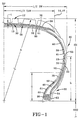
  • a radial ply tire 10 exhibiting very light weight and low rolling resistance has an aspect ratio in the 0.2 to 0.8 range.
  • the tire 10 has a pair of parallel annular bead cores 26; one or more radial carcass plies 38, at least one radial carcass ply 38 being wrapped around said bead cores 26; a belt structure 36 disposed radially outwardly of said one or more radial carcass ply 38 in a crown area of the tire 10; and an overlay 59 having a width coinciding substantially with the width of the belt structure 36.
  • a tread 12 is disposed radially outwardly of said overlay 59 and a sidewall 20 is disposed between the tread 12 and said beads 26.
  • the overlay 59 is preferably spirally wound radially outward of and adjacent to the belt structure 36.
  • the overlay 59 being made from a continuous strip of reinforcing tape having a width of 1 ⁇ 2 inch to 11 ⁇ 2 inches (1.3 to 3.8 cm) having 4 to 45 parallel reinforcing filaments or cord 70 embedded therein.
  • “Casing” means the carcass, belt structure, beads, sidewalls and all other components of the tire excepting the tread and undertread.
  • Core means one of the reinforcement strands of which the plies in the tire are comprised.
  • Ring and radially mean directions radially toward or away from the axis of rotation of the tire.
  • “Section Height” means the radial distance from the nominal rim diameter to the outer diameter of the tire at its equatorial plane.
  • Tire 10 as illustrated in Fig. 1 is a radial passenger or light truck tire; the tire 10 is provided with a ground-engaging tread portion 12 which terminates in the shoulder portions at the lateral edges 14,16 of the tread 12 respectively.
  • a pair of sidewall portions 20 extends from tread lateral edges 14,16 respectively and terminates in a pair of bead regions 22 each having an annular inextensible bead core 26 respectively.
  • the tire 10 is further provided with a carcass reinforcing structure 30 which extends from bead region 22 through one sidewall portion 20, tread portion 12, the opposite sidewall portion 20 to bead region 22.
  • belt structure 36 comprises two cut belt plies 50,51 and the cords 80 of belt plies 50,51 are oriented at an angle of about 22 degrees with respect to the mid-circumferential centerplane of the tire.
  • the carcass reinforcing structure 30 comprises at least one reinforcing ply structure 38.
  • a reinforcing ply structure 38 with a radially outer ply turnup 32 this ply structure 38 has preferably one layer of parallel cords 41.
  • the cords 41 of reinforcing ply structure 38 are oriented at an angle of at least 75 degrees with respect to the mid-circumferential centerplane CP of the tire 10. In the particular embodiment illustrated, the cords 41 are oriented at an angle of about 90 degrees with respect to the mid-circumferential centerplane CP.
  • the maximum section height SH of the tire shall be considered the radial distance measured from the nominal rim diameter NRD of the tire to the radially outermost part of the tread portion of the tire.
  • the nominal rim diameter shall be the diameter of the tire as designated by its size.
  • the axially outer component 53 has a radially inner end that is radially outward of the outer surface of the bead core 26 by about 1 cm.
  • the axially inner and axially outer components 52,53 preferably have rayon, nylon, aramid or steel cord reinforcement, in the preferred embodiment tire nylon 1400/2 dTex cords were used.
  • the second end 55 of the cord reinforced member 53 is located radially outward of the bead core 26 and the termination 33 of the turnup end 32 of the first ply 38 and it is radially located at a distance at least 50% of the section height SH as measured from the nominal bead diameter.
  • a fabric reinforced member 61 may be added to the bead regions 22 of the tire 10.
  • the fabric reinforced member has first and second ends 52,63.
  • the member is wrapped about the first ply 38 and the bead core 26. Both the first and the second ends 62,63 extend radially above and outward of the bead core 26.
  • the maximum section width (SW) of the tire is measured parallel to the rotational axis of the tire from the axially outer surfaces of the tire, exclusive of indicia, adornment and the like.
  • the tread width is the axial distance across the tire perpendicular to the equatorial plane (EP) of the tire as measured from the footprint of the tire inflated to maximum standard inflation pressure, at rated load and mounted on a wheel for which it was designed.
  • the inserts 46 may alternatively be loaded with short fibers, which are preferably oriented at an angle of at least 45° to enhance the radial and lateral stiffness of the insert, preferably the fibers are radially oriented.
  • the short fibers are made of textile or synthetic materials such as rayon, nylon, polyester or aramid. These short fibers can be radially directed or positioned at bias angles preferably at least 45° but should not be circumferentially extending.
  • This wide flat tread arc permits the belt cords 80 to experience minimal thermal shrinkage distortion which could damage cords of the ply 51, adjacent the carcass ply 38.
  • This in combination with the ply cords 41 of low thermal shrinkage and an overlay 59 of similar low thermal shrinkage means that the tire 10 can be manufactured and placed in use such that the fiberglass belts 50,51 will survive the exposure to thermal expansion and contraction.
  • the reduced weight of the unsprung tire mass allows the car manufactures to redesign the suspension with reduced weight components to improve car weight, performance and handling.

Abstract

A very light weight tire 10 has at least one radial ply 38 and a fiberglass belt structure 36 covered by an overlay 59 having cords 80 selected from the group of aramid, rayon, PEN, PET and PVA. The tire 10 has a very thin or reduced gauge (t) undertead 13. The tire 10 can be made having very low rolling resistance due to the combination of casing structure and the reduced rubber mass.

Description

Technical Field
This invention relates to pneumatic tires. More particularly to light weight radial ply tires having an aspect ratio of less than 0.8.
Background of the Invention
Tire engineers have historically attempted to build very durable casing structures that can survive the severe driving conditions that the vehicle operators put the tires through.
Early on tires were very heavy and employed many layers or plies of bias cord. The primary objective was to simply retain the air and avoid a flat or deflation.
Through a process of endless research to develop more durable and better tire constructions new materials and better designs have been developed.
The introduction of the radial tire made it practical to develop tires having as few as one carcass ply. The ply was contained radially by a belt structure. To enhance the durability of the tire these belt structures evolved to become primarily steel reinforced. These steel reinforced belts yielded and currently provide a very durable structure.
These steel belted tires have many benefits that make their use attractive. The steel cords are not heat sensitive that is their physical properties are pretty much constant regardless of the tire's operating temperature. The steel cords are substantially inextensible and the cords can be made very high strength with fine filaments that have excellent fatigue resistance. Nevertheless these steel corded belts in tires have resulted in the need to add rubber gauge directly above the belts in the area commonly referred to as the undertread, in the belt layers themselves and in the areas of the belt edges, all in an attempt to keep these steel cords from becoring exposed or structurally separating at the edges. Furthermore, the glass reinforced cord has a tenacity of 10 g/denier compared to steel cord used in belts having 4 g/denier.
The resultant effect has been that the steel belted radial tires are in fact heavier using more rubber in the tread area and in the tire's shoulders. It is precisely in these areas that a large part of the tire's tread wear performance and sensitivity to rolling resistance must be the highest. The more rubber in this area the higher the hysteresis effects and higher the temperatures under running conditions.
It is now an object of tire designers to develop tires that generate lower car fuel consumption. This can be achieved by designing cool running tires that have low mass and low rotational inertia while increasing the tire's handling performance and treadwear, furthermore, the engineer must insure that the tire's footprint and the contact patch of the tread has a uniform pressure distribution in order to achieve uniform wear.
With the advent of high performance tires having very low aspect ratios the use of belt structures having overlays of synthetic cords of nylon or aramid has been common. To further achieve high speed performance the tread thickness has been kept at a minimum. Thick tread mass at high speeds simply want to fly off the tire. As these tires are pushed to the engineer's known tire design limit he must rethink the entire parameters of the tire. In some cases this means going back and reanalyzing the concepts that were used in the past but were abandoned as a result of those in the art pursuing a different path.
One such approach that heretofore had lost favor among tire engineers was the use of fiberglass belts which although a very good material for belts lost favor when steel belts were introduced. The primary downfall of fiberglass belts was their apparent lack of durability.
Even in the bias tires of the 1970's the use of fiberglass breakers had technical concerns. In US-A-3,762,458 issued to Yoshida et al., it is stated that "Glass is superior to organic fiber cord in the heat resistance, dimensional stability and modulus of elasticity and when rubber is reinforced with glass cord and used as a breaker layer of a pneumatic tire, the tire is excellent in various properties, particularly is excellent in the abrasion resistance (road test) and cornering power."
Yoshida et al., then goes into detail as to why fiberglass cords were being disfavored in their use as breaker cords. He cites three serious drawbacks of the use of fiberglass breakers.
"Firstly, when a car is running, dynamic bending transformation and impact transformation of the tire occurred due to the road surface condition, and the glass cords are broken or crushed.
Secondly, in general, foreign materials, such as nails, glass pieces and gravels, are penetrated into the tire and reached its breaker layer during the use of the tire, particularly at the end of the use. In this case, if the tire has a breaker layer composed of conventional organic fibers, such as nylon, rayon, polyester and vinylon (polyvinyl alcohol) fibers, etc., breakage of the tire occurs only at the portion to which the foreign materials have been penetrated. On the contrary, if the tire has a glass cord breaker layer, the glass cords are crushed by the penetrated foreign materials and the breakage of the glass cords extends along the glass cord breaker layer. This is a cause of serious troubles.
In order to solve these drawbacks, there has been tried to arrange organic fiber cords, such as nylon cords, on the tread side of the glass cord breaker layer. however, a satisfactory result has not hitherto been obtained.
In addition to these drawbacks of glass cord, the inventors further have found a third drawback of glass cord, which is peculiar to glass cord and does not occur in organic fiber cord.
That is, in the vulcanization step of tire, the following step may be carried out. Namely, a tire is vulcanized at a high temperature and under a high pressure, and then the tire is taken out into an atmosphere at room temperature and under atmospheric pressure, and thereafter the tire is applied with air pressure to the inner side under a high pressure to stabilize the dimension of the tire. When the tire is taken out into the atmosphere at room temperature, cords composed of organic fibers other than glass fiber, such as rayon, nylon, vinylon and polyester fibers, etc., which are used as a reinforcing material of tire, that is, used in a carcass arranged on the inner side of breaker, are highly shrunk. As the result, glass cord breaker arranged directly adjacent to the rubber coated organic fiber cord layer (carcass) is compressed violently, and glass filaments constituting the glass cord of the breaker are compressed to decrease their tenacity and are broken during the car is running.
For instance, in a tire composed of 2 kinds of layers of a carcass layer reinforced with organic fiber cord and a glass cord breaker, glass cords constituting a glass cord breaker layer arranged on the carcass side are inferior in the tenacity to glass cords constituting another glass cord breaker layer arranged on the tread side.
Further, when organic fiber cords having different shrinkabilities, for example, nylon cord or rayon cord is used as a carcass cord, the nylon cord having a higher shrinkability decreases the tenacity of glass cord more than the rayon cord.
Further, even in the vulcanization treatment of conventional bias-belted tires in which rubber coated organic fiber cord layer, such as rubber coated nylon cord layer, is arranged on the tread side of the glass cord breaker, the above described phenomenon occurs between the glass cord breaker and the rubber coated organic fiber cord layer, whereby glass filaments are broken. Because, when the tire is cooled, the above described organic fiber cord shrinks considerably."
These three problems were allegedly solved by Yoshida et al., as quoted below:
  • "Among the above described three drawbacks of the tire having the glass cord breaker layer, the first drawback has already been solved by the inventors. That is, in order to decrease the bending transformation and impact transformation of glass cord, a short cut fiber reinforced rubber layer is arranged on the tread side of the glass cord breaker layer. In order to solve the second drawback, that is, the problem of plunger resistance against foreign materials, the inventors have confirmed that the arrangement of the short cut fiber reinforced rubber layer on the tread side of the glass cord breaker layer has a higher effect than the arrangement of a sole rubber layer or a rubber coated cord layer.
  • Furthermore, in order to solve the third drawback, the inventors have found that the following arrangement is more effective. That is, the glass cord breaker layer is not arranged directly adjacent to organic fiber cords having a high shrinkability, but such a layer that has a low shrinkability and does not transmit the shrinkage of the organic fiber cords to the glass cord breaker layer is arranged between the rubber coated organic fiber cord layer (carcass) and the glass cord breaker layer."
    Thus, Yoshida et al., attempted to retain the use of fiberglass breakers in bias tires.
    The use of fiberglass belts in radial tires was even more challenging. In U.S. patent to Christian M. L. L. Bourcier de Carbon of France, de Carbon explains "Radial carcass tires essentially comprise a radial carcass, made up of curved members which are straight in the center planes of the cover, in combination with a non-extensible belt comprising a reinforcement which is flexible in the radial direction (the direction perpendicular to the tread surface) but has high longitudinal and transverse rigidity (i.e., in directions parallel to the tread surface), the non-extensible belt being automatically tensioned by the internal pressure and thus having a considerable equatorial binding effect on the curved members of the carcass, even when the pneumatic tire is at rest and is not subjected to any crushing load."
    De Carbon's solution to the problem of radial tire belt structures was the use of flattened cords having a width of about 1 mm, the highly flattened cords being of steel plastic or glass fiber oriented at cross angles of 45° to 60°. As can easily be appreciated such solutions were very complicated and ultimately lost any commercial interest due to their complexity and the concurrent simpler success of steel belts.
    The most relevant prior art patent can be found in document EP-A- 412 928 which disclosed the features generally described in the preamble of claim 1.
    The present invention demonstrates that the use of fiberglass belts can again be made commercially acceptable if the fiberglass is employed with a combination of other components that insure that the glass cords are not damaged during manufacture by insuring that the thermal shrinkage differentials created during vulcanization, cooling and subsequent re-inflation are not transmitted to the glass cords. The fiberglass belts not only are commercially acceptable but also can provide surprisingly beneficial improvements in tire weight and reduced rolling resistance.
    Summary of the Invention
    A radial ply tire 10 exhibiting very light weight and low rolling resistance has an aspect ratio in the 0.2 to 0.8 range. The tire 10 has a pair of parallel annular bead cores 26; one or more radial carcass plies 38, at least one radial carcass ply 38 being wrapped around said bead cores 26; a belt structure 36 disposed radially outwardly of said one or more radial carcass ply 38 in a crown area of the tire 10; and an overlay 59 having a width coinciding substantially with the width of the belt structure 36. A tread 12 is disposed radially outwardly of said overlay 59 and a sidewall 20 is disposed between the tread 12 and said beads 26.
    The overlay 59 has filaments or cords 70, the cords 70 being selected form a group of materials, the group being rayon, PET, aramid, PEN, or PVA embedded in an elastomer. The belt structure 36 is made from two fiberglass cord reinforced layers 50,51 having cord angles in the range of 18° to 26°, preferably about 22°. The layers 50,51 are single cut layers requiring no folded lateral edges.
    The overlay 59 is preferably spirally wound radially outward of and adjacent to the belt structure 36. The overlay 59 being made from a continuous strip of reinforcing tape having a width of ½ inch to 1½ inches (1.3 to 3.8 cm) having 4 to 45 parallel reinforcing filaments or cord 70 embedded therein.
    In the preferred embodiment the overlay cords 70 are aramid, however, cords of high tensile strength, low thermal shrinkage such as rayon, PEN, PET or PVA can be used as well.
    The tire 10 according to the invention has a very thin undertread 13, the undertread 13 being measured from the radially outer surface of the cords 70 of the overlay 59 to a circumferential groove of full depth. The undertread 13 thickness (t) is less than 2 mm preferably above 1 mm.
    To enhance handling performance the tire 10 employs a hard apex 46 extending radially outwardly of each bead core 26 and adjacent the ply 38. The apex 46 have a shore D hardness greater than 50.
    To enhance lateral stability the tire 10 it can employ two sidewall inserts, one insert being in each sidewall 20. Each sidewall insert has two layers 52,53 of bias cord reinforcements. The cords of the first layer 52 oriented equal but opposite to the cords of the second layer 53, the two layers 52,53 being interposed between the apex 46 and the turnup 32 of the carcass ply 38. The cords of each layer are oriented at an angle of 25° to 60° relative to the radial direction. Preferably, the first and second layer 52,53 has a radially inner end 54 and a radially outer end 55, the respective ends 54,55 of one layer being staggered relative to the ends 54,55 of the opposite layer. The radially outer end 55 of one layer is located at about one-half of the tire's section height SH or at location h as shown.
    The tire 10 further has a noise dampening gumstrip 42 lying below a belt edge and extending to about 50% of the section height SH of the tire 10.
    The cords 41 of the one or more carcass plies 38 can be selected from the group of rayon, nylon, PEN, PET, steel, or aramid. The preferred tire 10 employed one rayon carcass ply 38.
    The tire 10 using the novel combination described above can be made very light weight compared to conventional tires.
    The inventive tire 10 can demonstrate excellent performance, particularly high speed handling with the added benefit of very low rolling resistance.
    Brief Description of the Drawing
    Fig. 1 is a cross-sectional view of the preferred embodiment tire 10 according to the present invention.
    Definitions
    "Aspect Ratio" means the ratio of its section height to its section width.
    "Axial" and "axially" means the lines or directions that are parallel to the axis of rotation of the tire.
    "Bead" or "Bead Core" means generally that part of the tire comprising an annular tensile member, the radially inner beads are associated with holding the tire to the rim being wrapped by ply cords and shaped, with or without other reinforcement elements such as flippers, chippers, apexes or fillers, toe guards and chafers.
    "Belt Structure" or "Reinforcing Belts" means at least two annular layers or plies of parallel cords, woven or unwoven, underlying the tread, unanchored to the bead, and having both left and right cord angles in the range from 17° to 27° with respect to the equatorial plane of the tire.
    "Circumferential" means lines or directions extending along the perimeter of the surface of the annular tread perpendicular to the axial direction.
    "Carcass" means the tire structure apart from the belt structure, tread, and undertread, but including the beads.
    "Casing" means the carcass, belt structure, beads, sidewalls and all other components of the tire excepting the tread and undertread.
    "Chafers" refers to narrow strips of material placed around the outside of the bead to protect cord plies from the rim, distribute flexing above the rim.
    "Cord" means one of the reinforcement strands of which the plies in the tire are comprised.
    "Equatorial Plane (EP)" means the plane perpendicular to the tire's axis of rotation and passing through the center of its tread.
    "Footprint" means the contact patch or area of contact of the tire tread with a flat surface at zero speed and under normal load and pressure.
    "Innerliner" means the layer or layers of elastomer or other material that form the inside surface of a tubeless tire and that contain the inflating fluid within the tire.
    "Normal Inflation Pressure" means the specific design inflation pressure and load assigned by the appropriate standards organization for the service condition for the tire.
    "Normal Load" means the specific design inflation pressure and load assigned by the appropriate standards organization for the service condition for the tire.
    "Ply" means a layer of rubber-coated parallel cords.
    "Radial" and "radially" mean directions radially toward or away from the axis of rotation of the tire.
    "Radial Ply Tire" means a belted or circumferentiallyrestricted pneumatic tire in which at least one ply has cords which extend from bead to bead are laid at cord angles between 65° and 90° with respect to the equatorial plane of the tire.
    "Section Height" means the radial distance from the nominal rim diameter to the outer diameter of the tire at its equatorial plane.
    "Section Width" means the maximum linear distance parallel to the axis of the tire and between the exterior of its sidewalls when and after it has been inflated at normal pressure for 24 hours, but unloaded, excluding elevations of the sidewalk due to labeling, decoration or protective bands.
    "Shoulder" means the upper portion of sidewall just below the tread edge.
    "Sidewall" means that portion of a tire between the tread and the bead.
    "Tread Width" means the arc length of the tread surface in the axial direction, that is, in a plane parallel to the axis of rotation of the tire.
    Detailed Description of the Invention
    The tire 10 according to the present invention employs a unique structure. Tire 10 as illustrated in Fig. 1 is a radial passenger or light truck tire; the tire 10 is provided with a ground-engaging tread portion 12 which terminates in the shoulder portions at the lateral edges 14,16 of the tread 12 respectively. A pair of sidewall portions 20 extends from tread lateral edges 14,16 respectively and terminates in a pair of bead regions 22 each having an annular inextensible bead core 26 respectively. The tire 10 is further provided with a carcass reinforcing structure 30 which extends from bead region 22 through one sidewall portion 20, tread portion 12, the opposite sidewall portion 20 to bead region 22. The turnup ends 32 of at least one radial ply 38 carcass reinforcing structure 30 are wrapped about bead cores 26 and extend radially outwardly to a terminal end 33. The turnup 32 may end at about the radial location of the maximum section width in the embodiment of Fig. 1. The tire 10 may include a conventional innerliner 35 forming the inner peripheral surface of the tire 10 if the tire is to be of the tubeless type. In the preferred tire 10 the innerliner 35 is made of 100% bromobutyl.
    As shown in Fig. 1 the tire 10 can employ a single synthetic ply wrapped over the bead core 26 and extending to a high turnup end 33 located at about the radial location of the maximum section diameter (h).
    Placed circumferentially about the radially outer surface of carcass reinforcing structure 30 beneath tread portion 12 is a tread reinforcing belt structure 36. In the particular embodiment illustrated, belt structure 36 comprises two cut belt plies 50,51 and the cords 80 of belt plies 50,51 are oriented at an angle of about 22 degrees with respect to the mid-circumferential centerplane of the tire.
    The cords 80 of belt ply 50 are disposed in an opposite direction to the mid-circumferential centerplane and from that of the cords 80 of belt ply 51. However, the belt structure 36 may comprise any number of belt plies and the cords 80 may be disposed at any desired angle preferably in the 18° to 26° range. An important feature of the layers 50,51 is that each layer 50,51 is a single cut layer, neither layer having folded lateral edges. The belt structure 36 provides lateral stiffness across the belt width so as to minimize lifting of the tread 12 from the road surface during operation of the tire 10. In the embodiments illustrated, this is accomplished by making the cords 80 of belt plies 50,51 of fiberglass and preferably fiberglass 660/1Tex having a density of 15-25 EPI (6-10 EPcm) construction.
    The carcass reinforcing structure 30 comprises at least one reinforcing ply structure 38. In the particular embodiment illustrated in Fig. 1, there is provided a reinforcing ply structure 38 with a radially outer ply turnup 32, this ply structure 38 has preferably one layer of parallel cords 41. The cords 41 of reinforcing ply structure 38 are oriented at an angle of at least 75 degrees with respect to the mid-circumferential centerplane CP of the tire 10. In the particular embodiment illustrated, the cords 41 are oriented at an angle of about 90 degrees with respect to the mid-circumferential centerplane CP. The cords 41 may be made of any material normally used for cord reinforcement of rubber articles, for example, and not by way of limitation, rayon, nylon and polyester, aramid or steel. Preferably, the cords are made of material having a high adhesion property with rubber and high heat resistance.
    For the carcass cords 41, organic fiber cords with an elastic modulus in the range of 250 to 1400 kgf/sq mm such as nylon 6, nylon 6-6, rayon, polyester or high-modulus cords, commonly are used. In the case of 340-to-2100 dTex such fiber cords are used preferably at a density of 17 to 30 EPI (6.6-12 EPcm).
    Other high modulus fiber include aramid, vinylon, PEN, PET, PVA, carbon fiber, glass fiber, polyamides. Alternatively, steel cords of very high tensile strength steel having fine diameter filaments exhibiting excellent fatigue resistance could be used. In the particular preferred embodiment illustrated, the cords 41 are made from rayon. The cords 41 have a modulus E of X and a percent elongation of Y. The preferred rayon cord 41 has X values in the range of at least to 10 GPa and percent elongations in the range commonly found in the specific material of the cord.
    As further illustrated in Fig. 1, the bead regions 22 of the tire 10 each have an annular substantially inextensible first and second bead cores 26 respectively.
    The bead core is preferably constructed of a single or monofilament steel wire continuously wrapped. In the preferred embodiment 0.038 inch (0.97 mm) diameter high tensile steel wire is wrapped in four layers radially inner to radially outer of four wires, respectively, forming a 4x4 construction.
    Located within the bead region 22 and the radially inner portions of the sidewall portions 20 are high modulus elastomeric apex inserts 46 disposed between carcass ply reinforcing structure 38 and the turnup ends 32, respectively. The elastomeric apex inserts 46 extend from the radially outer portion of bead cores 26 respectively, up into the sidewall portion gradually decreasing in cross-sectional width. The elastomeric inserts 46 terminate at a radially outer end at a distance G radially inward of the maximum section width of the tire at the location (h) as shown in Fig. 1. In the particular embodiment illustrated, the elastomeric apex inserts 46 each extend, from their respective bead cores 26 to a distance G of approximately 25 percent (25%) of the tire's section height.
    For the purposes of this invention, the maximum section height SH of the tire shall be considered the radial distance measured from the nominal rim diameter NRD of the tire to the radially outermost part of the tread portion of the tire. Also, for the purposes of this invention, the nominal rim diameter shall be the diameter of the tire as designated by its size.
    In a preferred embodiment of the invention the bead regions 22 further includes at least one cord reinforced member 52,53 located between the apex insert 46 and the ply turnup end 32. The cord reinforced member or members 52,53 have a first end 54 and a second end 55. The first end 54 is axially and radially inward of the second end 55. The cord reinforced member or members 52,53 increase in radial distance from the axis of rotation of the tire 10 as a function of distance from its first end 54. In the illustrated Fig. 1, the cord reinforced member comprises two components 52,53 having a width of about 4 cm. The axially inner component 52 has a radially inner end 54 that is radially at or slightly above the first and second bead cores 26. The axially outer component 53 has a radially inner end that is radially outward of the outer surface of the bead core 26 by about 1 cm. The axially inner and axially outer components 52,53, preferably have rayon, nylon, aramid or steel cord reinforcement, in the preferred embodiment tire nylon 1400/2 dTex cords were used. The second end 55 of the cord reinforced member 53 is located radially outward of the bead core 26 and the termination 33 of the turnup end 32 of the first ply 38 and it is radially located at a distance at least 50% of the section height SH as measured from the nominal bead diameter.
    The cords of members 52,53 are preferably inclined forming an included angle relative to the radial direction in a range from 25° to 75°, preferably 55°. If two members are employed, the cord angles are preferably equal but oppositely disposed. The cord reinforcement member 52,53 improves the handling characteristics of the tire 10 of the present invention. The members 52,53 greatly reduce the tendency for the car to oversteer, a significant problem encountered in conventional tires that are driven while uninflated or underinflated.
    A fabric reinforced member 61 may be added to the bead regions 22 of the tire 10. The fabric reinforced member has first and second ends 52,63. The member is wrapped about the first ply 38 and the bead core 26. Both the first and the second ends 62,63 extend radially above and outward of the bead core 26.
    The sidewall portions 20 of the preferred embodiment tire 10 are provided with a pair of first noise dampening fillers 42. The first noise dampening fillers 42 are employed between the innerliner 35 and the reinforcement ply 38. The first fillers 42 extend from under each belt edge in the shoulder region of tire 10 to radially inward of the reinforced member end 55. As illustrated in the preferred embodiment of the invention as shown in Fig. 1, the sidewall portions 20 each include a first noise dampening filler 42 and an apex insert 46. The first fillers 42 are positioned as described above. The apex inserts 46 are located between the first ply 38 and the turnup ends 32 of ply 38 respectively.
    For purposes of this invention, the maximum section width (SW) of the tire is measured parallel to the rotational axis of the tire from the axially outer surfaces of the tire, exclusive of indicia, adornment and the like. Also, for the purposes of this invention the tread width is the axial distance across the tire perpendicular to the equatorial plane (EP) of the tire as measured from the footprint of the tire inflated to maximum standard inflation pressure, at rated load and mounted on a wheel for which it was designed.
    The tire 10 illustrated in Fig. 1 of the preferred embodiment tire has a fabric overlay layer 59 disposed about the tread reinforcing belt structure 36. For example, two ply layers ideally spirally wound having PEN, PET, PVA, rayon or aramid cords may be disposed above each reinforcing belt structures 36, the lateral ends extending past the lateral ends of the belt structures 36. Alternatively, a single layer of spirally wound reinforced fabric can be employed as an overlay. The preferred embodiment tire 10 employed spirally wound aramid cords 70, of the flexten 1670/3 dTex or more preferably 1100/2 dTex. The aramid material has a substantially higher modulus of elasticity than nylon and accordingly results in a stronger tire reinforcement than two layers of nylon. Nylon exhibiting high thermal shrinkage should be avoided because its use will damage the fiberglass cords 80 of the belts 50,51. Applicants have found that an increase in high speed capability can be achieved in a tire with the single layer of aramid overlay having at least 14 EPI (5.5 EPcm), preferably about 17 EPI (6.6 EPcm). Generally the use of aramid material in passenger tire applications is avoided due in part to the fact that the material exhibits poor noise properties that resonate sounds through the relatively thin sidewalk of the passenger tire. Applicants' tire of the present invention employs a noise dampening insert 42 in the sidewalls 20 which noticeably dampen tire generated noises. These noise dampening sidewalls 20 permit the use of an aramid overlay without experiencing unacceptable noise levels.
    The cords 80 of the overlay 59 alternatively can be made of rayon, PET, PEN or PVA. A PEN filament having a density of 240 dTex to 2200 dTex can be employed, more preferably 1440/2 dTex having both a yarn and cord twist of between 4 and 12 tpi (1.6 and 4.7 tpcm), preferably 7Z/9S can be employed.
    The apex insert fillers 46, as shown, can be made of one or two or more distinct elastomeric materials. The preferred embodiments employed only one compound or material in the apex inserts 46 which extended from the bead core 26. The preferred apex insert material is very hard having a shore D hardness of 50 or more, preferably 50 to 55. The hardness of the insert 46 was achieved by crosslinked reinforcing resins mixed to a commonly known mixing procedure to achieve a high hardness which permits a minimal amount of material to be used to form the apex insert 46.
    The inserts 46 may alternatively be loaded with short fibers, which are preferably oriented at an angle of at least 45° to enhance the radial and lateral stiffness of the insert, preferably the fibers are radially oriented. Preferably the short fibers are made of textile or synthetic materials such as rayon, nylon, polyester or aramid. These short fibers can be radially directed or positioned at bias angles preferably at least 45° but should not be circumferentially extending.
    Chafing of the tire 10 in the lower bead region radially outward of the carcass structure 30 adjacent the rim flange may be minimized, especially during use of the tire in an underinflated condition, by providing hard rubber chafer portion 60.
    The belt structure 36 has belts 50,51 which preferably used fiberglass 660/1 Tex at a density of 15 to 25 EPI (6 to 10 EPcm). The belts 50,51 had a width of about 98% of the mold tread cord width commonly referred to as the tread arc width.
    To further enhance the tire 10 performance and light weight features the tread 12 was constructed having a minimal gauge or thickness (t) of the undertread 13. Conventionally for high performance passenger tire the undertread is reduced to between 2 and 5 mm. The tire of the present invention had an undertread less than 2 mm, preferably about 1 mm as measured from the radially outer cords 70 of the overlay 59 to a full depth circumferential groove bottom as shown in Fig. 1.
    To insure the inventive tire 10 reduced the inherent stresses created when molding a tire having fiberglass belts 50,51 it was determined that the mold should be wide and flat at the tread. The tread radius of 315 mm and a tread cord width of 141 mm was evaluated with acceptable results. In a tire size of 195/65R15 91V, a tread radius of 914 mm and a tread cord width of 152 mm yielded most superior results. The inventors believe that a flat tread radius greater than 300 mm over a tread cord width of about 125 mm or more will provide acceptable results. More preferably the tread radius R should be greater than 500 mm for tread cord width of greater than 150 mm, most preferably R should be at least 750 mm. This wide flat tread arc permits the belt cords 80 to experience minimal thermal shrinkage distortion which could damage cords of the ply 51, adjacent the carcass ply 38. This in combination with the ply cords 41 of low thermal shrinkage and an overlay 59 of similar low thermal shrinkage means that the tire 10 can be manufactured and placed in use such that the fiberglass belts 50,51 will survive the exposure to thermal expansion and contraction.
    A test tire 10 having a size 195/65R15 91V was made with the conventional steel belts the tire weight was 9.4 Kg. The same size tire made according to the present invention and has a weight of 7.2 Kg, depending on the tuning of the tire 10 the weight when employing the inventive concepts described above have yielded weights in the 6.9 to 7.4 Kg range.
    This weight reduction in and of itself was a most beneficial improvement over the prior art since it reduces the kinetic energy contribution of the tire, decreasing both translation and rotational kinetic energy and thus reducing fuel consumption.
    Additionally, the reduced weight of the unsprung tire mass allows the car manufactures to redesign the suspension with reduced weight components to improve car weight, performance and handling.
    The tire of the present invention brought about a 10% rolling resistance improvement versus a classic construction made in the same mold with the same tread compound.
    Treadwear improvements of 0 to 10% were observed in standard wear test of the tire 10 versus the conventional construction. The tire 10 was noticed to be less sensitive to wheel position wear. The shoulder wear of steering position and the centerline wear of the rear wheel position when lightly loaded were much less pronounced in the inventive tire 10 when compared to the prior art tires.
    Flatspotting of the inventive tire was very much improved over prior art tires in terms of the amount of time required to recover disturbance free ride. Flatspotting is a condition that commonly occurs when a vehicle after being driven is parked causing the warm tire to cool such that the structure has a locally flattened casing structure.
    Most importantly the inventive tire has demonstrated excellent durability and has passed plunger, high speed V, road durability carcass fatigue, outdoor resiliometer, curb impact test, road plunger and legally required DOT and ECE R30 qualification tests.

    Claims (19)

    1. A pneumatic radial ply tire (10) having an aspect ratio of 0.2 to 0.8 comprising a pair of parallel annular bead cores (26), one or more radial carcass plies (38), at least one radial carcass ply (38) having a pair of turnups (32) being wrapped around said bead cores (26), a belt structure (36) disposed radially outwardly of said one or more radial carcass plies (38) in a crown area of said tire (10), and an overlay (59) having a width coinciding substantially with the width of said belt structure (36), a tread (12) disposed radially outwardly of said overlay (59), said overlay (59) having reinforcement filaments or cords (70), the cords (70) being selected from a group of materials, the group being rayon, PET, aramid, PEN or PVA embedded in an elastomer, and said belt structure (36) being made from two fiberglass cord reinforced layers (50, 51) having cord angles in the range of 15° to 30° and a sidewall (20) disposed between said tread (12) and said beads (22), the tire (10) being characterized in that said tread (12) has a flat tread radius (R) of greater than 300 mm over a tread cord width of 125 mm or more, the radius (R) being 500 mm or more for tread cord widths of 150 mm or more and in that the tread (12) has an undertread (13) as measured from the radially outer surface of the cords (70) of the overlay (59) to a circumferential groove of full depth, the undertread (13) having an average thickness (t) of less than 2 mm.
    2. The tire (10) of claim 1 wherein said overlay (59) is spirally wound radially outward of said belt structure (36) and comprises a continuous strip of elastomeric reinforcing tape having a width of ½ inch to 1½ inches (1.3 to 3.8 cm) and 4 to 45 parallel reinforcing filaments or cords (70) embedded therein.
    3. The tire (10) of claim 1 wherein the reinforcement filaments (70) are PEN filaments have a density of 240 dTex to 2200 dTex.
    4. The tire (10) of claim 3 wherein said PEN reinforcement cords (70) have a twist multiplier of 5 to 10.
    5. The tire (10) of claim 4 wherein said PEN reinforcement (70) is 1440/2 dTex cords (70) having a yarn and cord twist of between 4 to 12 tpi (1.6 to 4.7 tpcm).
    6. The tire (10) of claim 1 wherein the reinforcement filaments (70) of the overlay (59) are aramid.
    7. The tire (10) of claim 5 wherein the reinforcement filaments (70) of the overlay (59) are flexten 1100/2 dTex.
    8. The tire (10) of claim 6 wherein the filaments (70) have an end per inch (EPI) of 15 to 30 (6 to 12 EPcm).
    9. The tire (10) of claim 8 wherein the undertread (13) has a thickness (t) of about 1 mm.
    10. The tire (10) of claim 1 having an apex (46) extending radially outwardly above each of the bead cores (26) and adjacent the ply (38), the apex (46) having a shore D hardness greater than 50.
    11. The tire (10) of claim 9 having two sidewall inserts, one insert in each sidewall, each insert being two elastomeric layers (52, 53) reinforced by bias cords, a first layer (52) being oriented equal but opposite to the second layer (53), the two layers being interposed between the apex (46) and the turnup (32) of the carcass ply (38).
    12. The tire (10) of claim 10 wherein the first and second layers (52, 53) have bias cord angles of 25° to 60°.
    13. The tire (10) of claim 11 wherein each first and second layer (52, 53) has a radially inner end (54) and a radially outer end (55), the respective ends (54, 55) of one layer (52, 53) being staggered relative to the ends (54, 55) of the opposite layer (52, 53), the radially outer end (55) of one layer being located at about one-half of the tire's section height (SH).
    14. The tire (10) of claim 1 having an innerliner (35) and a noise dampening elastomeric insert (42), the insert (42) lying between the innerliner (35) and the ply (38) below a belt edge and extending to about 50% of the section height (SH) of the tire (10).
    15. The tire (10) of claim 1 wherein the carcass plies (38) have radial cords (41) of rayon.
    16. The tire (10) of claim 1 wherein the carcass plies (38) have radial cords (41) of polyester.
    17. The tire (10) of claim 1 wherein the carcass plies (38) have radial cords (41) of PEN.
    18. The tire (10) of claim 1 wherein the carcass plies (38) have radial cords (41) of aramid.
    19. The tire (10) of claim 1 wherein the carcass plies (38) have radial steel cords (41).
    EP98920192A 1997-06-09 1998-05-04 Light weight fiberglass belted radial tire Expired - Lifetime EP0994783B1 (en)

    Applications Claiming Priority (3)

    Application Number Priority Date Filing Date Title
    US871261 1992-04-23
    US08/871,261 US6016858A (en) 1997-06-09 1997-06-09 Light weight fiberglass belted radial tire
    PCT/US1998/009046 WO1998056599A1 (en) 1997-06-09 1998-05-04 Light weight fiberglass belted radial tire

    Publications (2)

    Publication Number Publication Date
    EP0994783A1 EP0994783A1 (en) 2000-04-26
    EP0994783B1 true EP0994783B1 (en) 2002-02-06

    Family

    ID=25357058

    Family Applications (1)

    Application Number Title Priority Date Filing Date
    EP98920192A Expired - Lifetime EP0994783B1 (en) 1997-06-09 1998-05-04 Light weight fiberglass belted radial tire

    Country Status (13)

    Country Link
    US (1) US6016858A (en)
    EP (1) EP0994783B1 (en)
    JP (1) JP2002503176A (en)
    KR (1) KR100551869B1 (en)
    CN (1) CN1097524C (en)
    AT (1) ATE212918T1 (en)
    BR (1) BR9810244A (en)
    CA (1) CA2293648A1 (en)
    CZ (1) CZ292553B6 (en)
    DE (1) DE69803768T2 (en)
    PL (1) PL196122B1 (en)
    WO (1) WO1998056599A1 (en)
    ZA (1) ZA984576B (en)

    Families Citing this family (22)

    * Cited by examiner, † Cited by third party
    Publication number Priority date Publication date Assignee Title
    US6460588B1 (en) * 1997-09-26 2002-10-08 The Goodyear Tire & Rubber Company Pen reinforcement for rubber composites
    EP1022163B1 (en) * 1998-12-21 2005-02-16 Bridgestone Corporation Pneumatic radial tire
    JP2001039113A (en) * 1999-05-21 2001-02-13 Bridgestone Corp Pneumatic tire
    WO2002100940A1 (en) * 2001-06-08 2002-12-19 Thermoplastic Rubber Systems, Inc. Thermoplastic vulcanizates
    US20030008968A1 (en) * 2001-07-05 2003-01-09 Yoshiki Sugeta Method for reducing pattern dimension in photoresist layer
    US7329459B2 (en) * 2003-03-07 2008-02-12 Performance Fibers, Inc. Polymer-based reinforcement material and tire cord compositions and methods of production thereof
    US7490648B2 (en) * 2005-03-30 2009-02-17 The Goodyear Tire & Rubber Company Belt package for super single truck tires
    US7503363B2 (en) * 2005-03-30 2009-03-17 The Goodyear Tire & Rubber Company Belt package for super single truck tires
    US7775247B2 (en) * 2005-12-22 2010-08-17 The Goodyear Tire & Rubber Company Steel cord for reinforcement of off-the-road tires
    US20090095397A1 (en) * 2007-10-15 2009-04-16 Robert Anthony Neubauer Floating two-ply tire
    CA2732820A1 (en) * 2008-08-04 2010-02-11 Maurice Taylor Nylon and steel belted off-the-road (otr) radial tire
    US8037913B2 (en) * 2008-08-19 2011-10-18 The Goodyear Tire & Rubber Company Pneumatic tire with single non-continuous carcass ply
    US20100051162A1 (en) * 2008-08-29 2010-03-04 Robert Anthony Neubauer Modular two-ply tire with directional side plies
    US8322390B2 (en) * 2008-10-31 2012-12-04 The Goodyear Tire & Rubber Company, Inc. Light weight steel belted tire device
    DE102009025793A1 (en) 2009-02-19 2010-08-26 Continental Reifen Deutschland Gmbh Vehicle tires
    DE102010000014A1 (en) * 2010-01-07 2011-07-14 Continental Reifen Deutschland GmbH, 30165 Vehicle tires
    US9370971B2 (en) 2010-12-29 2016-06-21 Compagnie Generale Des Etablissements Michelin Methods for retreading a tire
    US8833355B2 (en) * 2011-06-07 2014-09-16 Jugs Sports, Inc. Pneumatic tire for throwing machine
    WO2013115810A1 (en) 2012-01-31 2013-08-08 Michelin Recherche Et Technique S.A. Projecting features molded within submerged tread voids
    BR112014023864A2 (en) * 2012-03-30 2017-08-22 Michelin & Cie TIRE TREADS WITH REDUCED THICKNESS SUB-TREADMILL
    US20200156419A1 (en) * 2017-07-20 2020-05-21 Bridgestone Americas Tire Operations, Llc Puncture resistant tire
    JP6540915B1 (en) * 2017-11-20 2019-07-10 横浜ゴム株式会社 Pneumatic tire

    Family Cites Families (33)

    * Cited by examiner, † Cited by third party
    Publication number Priority date Publication date Assignee Title
    TR16723A (en) * 1970-07-10 1973-03-01 Pirelli IMPROVEMENT IN PROTECTIVE LAYER STRUCTURES OF RADIAL TIRES
    JPS5014001B1 (en) * 1970-11-27 1975-05-24
    US3785423A (en) * 1971-12-15 1974-01-15 Bourcier Carbon Christian Top reinforcement for pneumatic tires
    US3961657A (en) * 1974-05-03 1976-06-08 The Goodyear Tire & Rubber Company High speed radial ply tire
    JPS5243204A (en) * 1975-10-02 1977-04-05 Bridgestone Corp Flat air radial tire for heavy vehicle
    IT1073355B (en) * 1976-10-19 1985-04-17 Sarda Off Mecc Spa IMPROVEMENTS TO THE STRUCTURE OF RADIAL TIRES
    US4311628A (en) * 1977-11-09 1982-01-19 Monsanto Company Thermoplastic elastomeric blends of olefin rubber and polyolefin resin
    JPS5770707A (en) * 1980-10-16 1982-05-01 Bridgestone Corp Pneumatic radial tire
    US4513802A (en) * 1982-03-16 1985-04-30 Bridgestone Tire Company Limited Reduced rolling resistance pneumatic radial tire and method of manufacturing the same
    US4815511A (en) * 1986-03-18 1989-03-28 The Goodyear Tire & Rubber Company All-season high-performance radial-ply passenger pneumatic tire
    US4722989A (en) * 1987-03-16 1988-02-02 Air Products And Chemicals, Inc. Process for producing polyurethane/urea elastomers
    US4823855A (en) * 1987-11-23 1989-04-25 The Goodyear Tire & Rubber Company Pneumatic tire tread pattern
    CA2018018C (en) * 1989-08-10 1999-10-05 Rene Francois Reuter Pneumatic tire
    JPH048605A (en) * 1990-04-26 1992-01-13 Sumitomo Rubber Ind Ltd Radial tire
    JP2767502B2 (en) * 1991-04-12 1998-06-18 横浜ゴム株式会社 Pneumatic radial tires for passenger cars
    JPH05178005A (en) * 1991-12-27 1993-07-20 Yokohama Rubber Co Ltd:The Pneumatic radial tire
    US5385188A (en) * 1992-04-29 1995-01-31 The Yokohama Rubber Co., Ltd. Pneumatic radial tire for passenger cars
    JP3229381B2 (en) * 1992-08-27 2001-11-19 横浜ゴム株式会社 Pneumatic radial tire
    US5263526A (en) * 1992-09-30 1993-11-23 The Goodyear Tire & Rubber Company Pneumatic tire having specified bead structure
    US5368082A (en) * 1992-09-30 1994-11-29 The Goodyear Tire & Rubber Company Radial ply pneumatic tire
    CA2109264A1 (en) * 1992-10-30 1994-05-01 Akiyoshi Tamano Pneumatic tire
    US5529105A (en) * 1992-12-24 1996-06-25 Bridgestone Corporation Pneumatic tire including at least one tie-element layer with substantially orthogonally oriented cords
    EP0614774B1 (en) * 1993-03-08 1997-05-14 Sumitomo Rubber Industries Limited Pneumatic radial tyre
    US5443105A (en) * 1993-03-17 1995-08-22 Bridgestone Corporation Pneumatic radial tire with bead toe reinforcing rubber stock
    JPH07172117A (en) * 1993-04-16 1995-07-11 Sumitomo Rubber Ind Ltd Radial tire for motorcycle
    US5407701A (en) * 1993-05-14 1995-04-18 The Goodyear Tire & Rubber Company Cords for pneumatic tires and process for making them
    CA2108328A1 (en) * 1993-06-29 1994-12-30 Keith Carl Trares High ending, locked tie-in construction
    DE69509323T2 (en) * 1994-08-23 1999-08-26 Dunlop Gmbh Pneumatic vehicle tires
    US5535800A (en) * 1994-11-21 1996-07-16 The Goodyear Tire & Rubber Company Pneumatic tire for extended mobility featuring composite ribs
    US5538063A (en) * 1994-12-23 1996-07-23 The Goodyear Tire & Rubber Company Aircraft tire with reinforcement insert
    JP3555809B2 (en) * 1995-06-19 2004-08-18 株式会社ブリヂストン Radial tire
    DE19526408A1 (en) * 1995-07-19 1997-01-23 Sp Reifenwerke Gmbh Pneumatic vehicle tires
    ES2164216T3 (en) * 1995-08-24 2002-02-16 Bridgestone Corp ROBUST PNEUMATIC COVER WITH REDUCED NOISE.

    Also Published As

    Publication number Publication date
    KR100551869B1 (en) 2006-02-14
    AU724426B2 (en) 2000-09-21
    CA2293648A1 (en) 1998-12-17
    CZ292553B6 (en) 2003-10-15
    CZ444099A3 (en) 2000-08-16
    AU7282198A (en) 1998-12-30
    WO1998056599A1 (en) 1998-12-17
    CN1097524C (en) 2003-01-01
    KR20010013458A (en) 2001-02-26
    DE69803768D1 (en) 2002-03-21
    CN1259905A (en) 2000-07-12
    PL196122B1 (en) 2007-12-31
    BR9810244A (en) 2000-09-19
    JP2002503176A (en) 2002-01-29
    EP0994783A1 (en) 2000-04-26
    ZA984576B (en) 1998-12-03
    PL337347A1 (en) 2000-08-14
    ATE212918T1 (en) 2002-02-15
    DE69803768T2 (en) 2002-08-22
    US6016858A (en) 2000-01-25

    Similar Documents

    Publication Publication Date Title
    EP0988159B1 (en) Low cost light weight radial tire
    EP1019257B1 (en) Light weight aramid belted radial tire
    EP0994783B1 (en) Light weight fiberglass belted radial tire
    EP0984867B1 (en) An inextensible high temperature resistant runflat tire
    EP1023191B1 (en) Low cost runflat tire with improved carcass
    KR20010013040A (en) Runflat tire with improved carcass
    EP0346106A1 (en) Pneumatic tyre
    EP0984869B1 (en) Runflat tire with improved uninflated handling
    EP0413574A2 (en) High speed radial tyre
    EP1022162B1 (en) Tire with improved run-flat design
    EP1094955B1 (en) Improved sidewall with insert construction for runflat tire
    US6631748B1 (en) Sidewall with insert construction for runflat tire
    AU724426C (en) Light weight fiberglass belted radial tire
    EP1110758A2 (en) Tire with large bead diameter
    MXPA99010855A (en) Light weight fiberglass belted radial tire
    MXPA99010856A (en) Low cost light weight radial tire

    Legal Events

    Date Code Title Description
    PUAI Public reference made under article 153(3) epc to a published international application that has entered the european phase

    Free format text: ORIGINAL CODE: 0009012

    17P Request for examination filed

    Effective date: 20000110

    AK Designated contracting states

    Kind code of ref document: A1

    Designated state(s): AT DE ES FR GB IT

    AX Request for extension of the european patent

    Free format text: SI PAYMENT 20000110

    RIN1 Information on inventor provided before grant (corrected)

    Inventor name: CRAIG, DAVID, PATERSON

    Inventor name: PACKBIER, ERIC, GERARD, MARIE

    Inventor name: THISE-FOURGON, MARIE-RITA, CATHERINE, AMELIE

    Inventor name: SMITS, ATTE

    Inventor name: ROESGEN, ALAIN, EMILE, FRANCOIS

    RAX Requested extension states of the european patent have changed

    Free format text: SI PAYMENT 20000110

    GRAG Despatch of communication of intention to grant

    Free format text: ORIGINAL CODE: EPIDOS AGRA

    17Q First examination report despatched

    Effective date: 20010316

    GRAG Despatch of communication of intention to grant

    Free format text: ORIGINAL CODE: EPIDOS AGRA

    GRAH Despatch of communication of intention to grant a patent

    Free format text: ORIGINAL CODE: EPIDOS IGRA

    GRAH Despatch of communication of intention to grant a patent

    Free format text: ORIGINAL CODE: EPIDOS IGRA

    GRAA (expected) grant

    Free format text: ORIGINAL CODE: 0009210

    REG Reference to a national code

    Ref country code: GB

    Ref legal event code: IF02

    AK Designated contracting states

    Kind code of ref document: B1

    Designated state(s): AT DE ES FR GB IT

    AX Request for extension of the european patent

    Free format text: SI PAYMENT 20000110

    PG25 Lapsed in a contracting state [announced via postgrant information from national office to epo]

    Ref country code: AT

    Free format text: LAPSE BECAUSE OF FAILURE TO SUBMIT A TRANSLATION OF THE DESCRIPTION OR TO PAY THE FEE WITHIN THE PRESCRIBED TIME-LIMIT

    Effective date: 20020206

    REF Corresponds to:

    Ref document number: 212918

    Country of ref document: AT

    Date of ref document: 20020215

    Kind code of ref document: T

    REF Corresponds to:

    Ref document number: 69803768

    Country of ref document: DE

    Date of ref document: 20020321

    PG25 Lapsed in a contracting state [announced via postgrant information from national office to epo]

    Ref country code: ES

    Free format text: LAPSE BECAUSE OF FAILURE TO SUBMIT A TRANSLATION OF THE DESCRIPTION OR TO PAY THE FEE WITHIN THE PRESCRIBED TIME-LIMIT

    Effective date: 20020829

    PLBE No opposition filed within time limit

    Free format text: ORIGINAL CODE: 0009261

    STAA Information on the status of an ep patent application or granted ep patent

    Free format text: STATUS: NO OPPOSITION FILED WITHIN TIME LIMIT

    26N No opposition filed

    Effective date: 20021107

    PGFP Annual fee paid to national office [announced via postgrant information from national office to epo]

    Ref country code: GB

    Payment date: 20050406

    Year of fee payment: 8

    PG25 Lapsed in a contracting state [announced via postgrant information from national office to epo]

    Ref country code: GB

    Free format text: LAPSE BECAUSE OF NON-PAYMENT OF DUE FEES

    Effective date: 20060504

    GBPC Gb: european patent ceased through non-payment of renewal fee

    Effective date: 20060504

    PGFP Annual fee paid to national office [announced via postgrant information from national office to epo]

    Ref country code: IT

    Payment date: 20070519

    Year of fee payment: 10

    PGFP Annual fee paid to national office [announced via postgrant information from national office to epo]

    Ref country code: DE

    Payment date: 20080530

    Year of fee payment: 11

    PG25 Lapsed in a contracting state [announced via postgrant information from national office to epo]

    Ref country code: IT

    Free format text: LAPSE BECAUSE OF NON-PAYMENT OF DUE FEES

    Effective date: 20080504

    PG25 Lapsed in a contracting state [announced via postgrant information from national office to epo]

    Ref country code: DE

    Free format text: LAPSE BECAUSE OF NON-PAYMENT OF DUE FEES

    Effective date: 20091201

    PGFP Annual fee paid to national office [announced via postgrant information from national office to epo]

    Ref country code: FR

    Payment date: 20120510

    Year of fee payment: 15

    REG Reference to a national code

    Ref country code: FR

    Ref legal event code: ST

    Effective date: 20140131

    PG25 Lapsed in a contracting state [announced via postgrant information from national office to epo]

    Ref country code: FR

    Free format text: LAPSE BECAUSE OF NON-PAYMENT OF DUE FEES

    Effective date: 20130531