EP0994436B1 - Portable electro-optical device - Google Patents
Portable electro-optical device Download PDFInfo
- Publication number
- EP0994436B1 EP0994436B1 EP98830611A EP98830611A EP0994436B1 EP 0994436 B1 EP0994436 B1 EP 0994436B1 EP 98830611 A EP98830611 A EP 98830611A EP 98830611 A EP98830611 A EP 98830611A EP 0994436 B1 EP0994436 B1 EP 0994436B1
- Authority
- EP
- European Patent Office
- Prior art keywords
- electro
- optical device
- frame
- board
- optical
- Prior art date
- Legal status (The legal status is an assumption and is not a legal conclusion. Google has not performed a legal analysis and makes no representation as to the accuracy of the status listed.)
- Expired - Lifetime
Links
Images
Classifications
-
- G—PHYSICS
- G06—COMPUTING; CALCULATING OR COUNTING
- G06K—GRAPHICAL DATA READING; PRESENTATION OF DATA; RECORD CARRIERS; HANDLING RECORD CARRIERS
- G06K7/00—Methods or arrangements for sensing record carriers, e.g. for reading patterns
- G06K7/10—Methods or arrangements for sensing record carriers, e.g. for reading patterns by electromagnetic radiation, e.g. optical sensing; by corpuscular radiation
- G06K7/10544—Methods or arrangements for sensing record carriers, e.g. for reading patterns by electromagnetic radiation, e.g. optical sensing; by corpuscular radiation by scanning of the records by radiation in the optical part of the electromagnetic spectrum
- G06K7/10821—Methods or arrangements for sensing record carriers, e.g. for reading patterns by electromagnetic radiation, e.g. optical sensing; by corpuscular radiation by scanning of the records by radiation in the optical part of the electromagnetic spectrum further details of bar or optical code scanning devices
- G06K7/10881—Methods or arrangements for sensing record carriers, e.g. for reading patterns by electromagnetic radiation, e.g. optical sensing; by corpuscular radiation by scanning of the records by radiation in the optical part of the electromagnetic spectrum further details of bar or optical code scanning devices constructional details of hand-held scanners
Definitions
- the present invention relates to a portable electro-optical device.
- Portable electro-optical devices comprising an optical/electronic module and an external casing which contains the module are known.
- Devices of this type consist, for example, of laser guns for reading optical codes.
- the optical/electronic module comprises an optical unit and an electronic unit for controlling the optical unit and processing the signal.
- the optical unit contains a laser source which emits a laser beam and optical components for focusing and driving the laser beam.
- the optical components comprise movable mirrors which, depending on the technology used, are connected to a stepper motor or mounted on a resilient support.
- the electronic unit contains electronic components which are mounted on a printed circuit (or board) which also carries the optical components.
- bearings made of visco-elastic material have been used, said bearings being arranged between the external casing and the board supporting the optical and electronic units.
- annular rubber bearings are generally used, being mounted on brackets fixed to the board and housed in seats formed in the casing.
- US 5,543,609 discloses a hand-held scanner including a scan module and a frame arranged between the scan module and the scanner.
- the scan module is supported by the frame.
- the scanner is also provided with shock-protecting means interposed between the external casing and the frame and with vibration-isolating means interposed between the frame and the scan module.
- the vibration-isolation means consist of elastomeric sleeves intended to cooperate with threaded fasteners engaging co-linear threaded bores formed either in both the sides and the rear of the scan module.
- the object of the present invention is to eliminate the above-mentioned drawbacks.
- said frame is provided with bearing lugs for said board and at least one resilient tongue designed to co-operate with at least one lug in order to retain vertically said board in said frame.
- said supporting structure is of the controlled deformation type and is capable of dissipating energy resulting from said impact stresses.
- said module comprises an optical unit and an electronic unit both mounted on a board and said board is housed in said supporting structure.
- said supporting structure comprises a frame which supports said board and is provided with pins for connection to said external casing.
- said board is provided with at least one hole and said frame is provided with at least one hollow stud designed to penetrate into said hole so as to be fixed to said board.
- said at least one element is preferably in the form of a tooth.
- visco-elastic elements are arranged between said support frame and said external casing.
- said visco-elastic elements are rubber bearings.
- said rubber bearings are ring-shaped and are mounted on said pins.
- said casing comprises a base and a cover, said base and cover being provided with respective half-seats designed to house said pins.
- said half-seats are designed to house said bearings as well.
- said support frame is made of semi-rigid material.
- it consists of a polymer material chosen from the group comprising: nylon, acetal resins, polycarbonates and the like.
- said support frame is made of rigid material.
- said support frame is made of substantially resilient material.
- said optical unit comprises a laser source which emits a laser beam and optical components for focusing and driving said laser beam.
- said optical unit comprises a diffused light source and a sensor of the CCD or CMOS type.
- the electro-optical device has the advantage that the optical/electronic module remains correctly positioned in the frame without damage to components and without the laser beam undergoing misalignment.
- Fig. 1 shows an optical/electronic module 1 and a supporting structure 10 of an electro-optical device.
- the electro-optical device consists, for example, of a laser gun for reading optical codes.
- the module 1 comprises an optical unit 3 and an electronic unit 40 (shown as a block in broken lines) mounted on a board 2.
- the optical unit 3 comprises a laser (diode) source which emits a laser beam and optical components for focusing and driving the laser beam, which in turn comprise a movable mirror (not shown).
- the optical unit could contain a light source of the LED type and sensors of the CCD and CMOS type.
- the electronic unit comprises electronic components and a printed circuit formed on the board 2 and connected to a cable by means of electrical connections (not shown).
- the board 2 has a hole 5 and two eyelets 4, only one of which can be seen in Fig. 1.
- the hole 5 is located close to one end of the board 2 and the eyelets 4 are spaced from the hole 5 and are located in the vicinity of the optical unit 3 on two longitudinal sides of the board 2.
- Fig. 1 also shows a washer 6 and a screw 7, the function of which will be illustrated further below.
- the supporting structure 10 comprises a support frame 11 and four ring-shaped bearings 12.
- the frame 11 is formed in the manner of a shell and has a bottom wall 13 and side walls 14.
- the wall 13 is provided with a hollow stud 15 designed to penetrate into the hole 5 of the board 2.
- Lugs 16 and 116 are provided at the corners between the wall 13 and the walls 14.
- the walls 14 are provided with resilient tongues 18 (Fig. 2) designed to co-operate with pairs of underlying lugs 116 situated in the vicinity of the optical unit 3, in order to retain the board 2 in the frame 11 in the vertical direction.
- the walls 14 are also provided with teeth 19, only one of which can be seen in Fig.
- Each wall 14 is further provided with a pair of pins 20 for supporting the ring bearings 12.
- the bearings 12 could have other shapes: oval, rectangular, etc.
- the frame 11 is provided with openings 113 which allow the cable with the electrical connections of the printed circuit to pass through.
- the frame 11 is made, for example, of a controlled-deformation material, such as a semi-rigid material, in particular a polymeric material chosen from the group comprising: nylon, acetal resins, polycarbonates and the like. These materials represent the best compromise between elasticity, rigidity and strength.
- a controlled-deformation material such as a semi-rigid material, in particular a polymeric material chosen from the group comprising: nylon, acetal resins, polycarbonates and the like. These materials represent the best compromise between elasticity, rigidity and strength.
- the ring bearings 12 are made of visco-elastic material, for example rubber.
- the frame 11 may be made of a rigid material, such as a metallic material, or a substantially resilient material.
- the bearings 12 are made of a material such as to provide the structure 10 with the desired characteristics of capacity for absorption and dissipation of the impact energy.
- the optical/electronic module 1 is mounted in the frame 11, by splaying the side walls 14 and positioning the board 2 on the lugs 16 so that the stud 15 enters into the hole 5 and the teeth 19 engage inside the eyelets 4.
- the board 2 is retained between the tongues 18 and the pairs of underlying tugs 116.
- the ring bearings 12 are mounted on the pins 20.
- connection provided between the board 2 and the frame 11 by means of the eyelets 4 and the teeth 19, the lugs 16 and 116 and the tongues 18, allow relative movements of the board and the frame and prevent the deformations of the frame from being transmitted to the board.
- Fig. 3 shows a casing 25 in the form of a gun, which is designed to contain the group formed by the supporting structure 10 and the optical/electronic module 1.
- the casing may have a banana shape or other shape.
- the casing 25 comprises a base 26 and a cover 27 provided, respectively, with four half-seats 28 and four half-seats 29 for the pins 20 and the bearings 12.
- the half-seats 28 and 29 are formed by means of interstices delimited by wall portions 30 and 31 with semicircular edges.
- the base 26 has three through-holes 32 and the cover 27 has three blind holes 33.
- the holes 32 receive inside them screws, not shown, which are screwed into the holes 33 in order to fix the cover 27 to the base 26.
- the group formed by the structure 10 and the module 1 is mounted inside the cover 27 so that the ring bearings 12 are housed in the half-seats 29. Then the cover 27 is positioned on the base 26 so as to house the bearings 12 in the half-seats 28 and finally the cover 27 is screwed to the base 26.
- the support frame and the bearings may be moulded together and form a single body.
- the external casing and the support frame may be moulded together and connected by means of resilient bridge-pieces.
Abstract
Description
- The present invention relates to a portable electro-optical device.
- Portable electro-optical devices comprising an optical/electronic module and an external casing which contains the module are known. Devices of this type consist, for example, of laser guns for reading optical codes. In these devices the optical/electronic module comprises an optical unit and an electronic unit for controlling the optical unit and processing the signal. The optical unit contains a laser source which emits a laser beam and optical components for focusing and driving the laser beam. The optical components comprise movable mirrors which, depending on the technology used, are connected to a stepper motor or mounted on a resilient support. The electronic unit contains electronic components which are mounted on a printed circuit (or board) which also carries the optical components.
- These devices, and in particular laser guns, are manually operated by operators and it happens that, during use, they are frequently dropped. The external casing of the devices is fairly strong and is able to withstand the impacts, but it transmits to the optical/electronic module, which is fairly delicate, stresses which often impair correct operation thereof. In fact, on account of the frequent impacts, displacements of the optical components occur, with consequent misalignment of the laser beam and also damage and breakage of the optical and electronic components.
- Problems of an entirely similar nature are encountered in optical code readers which use an LED illumination system and sensors of the CCD (Charged Coupled Device) type or CMOS (Complementary Metal Oxide Semiconductor) type.
- In an attempt to solve the problem, bearings made of visco-elastic material have been used, said bearings being arranged between the external casing and the board supporting the optical and electronic units. In particular, annular rubber bearings are generally used, being mounted on brackets fixed to the board and housed in seats formed in the casing.
- However, this solution has proved to be unsatisfactory because, in various situations, twisting of the board has been found to occur, resulting in misalignment of the optical components and also detachment and/or breakage of optical or electronic components.
- The inventors have realised that, in the above-mentioned conditions, these drawbacks are due to the fact that the rubber bearings are able to protect the optical and electronic components only in the case of stresses due to impact forces which are substantially perpendicular to their bases, namely parallel to the longitudinal axis of the bearings. On the other hand, they are often unable to withstand effectively stresses due to impact forces which are differently oriented, for example shearing forces, which are substantially parallel to the bases of the bearings, or inclined forces. In these circumstances, all the forces acting on the casing are transmitted to the board in a more or less direct manner and are concentrated in restricted zones of the board, causing the above-mentioned damage.
- US 5,543,609 discloses a hand-held scanner including a scan module and a frame arranged between the scan module and the scanner. The scan module is supported by the frame. The scanner is also provided with shock-protecting means interposed between the external casing and the frame and with vibration-isolating means interposed between the frame and the scan module. The vibration-isolation means consist of elastomeric sleeves intended to cooperate with threaded fasteners engaging co-linear threaded bores formed either in both the sides and the rear of the scan module.
- The object of the present invention is to eliminate the above-mentioned drawbacks.
- The above-mentioned object is achieved, in accordance with the invention, by means of a portable electro-optical device as recited in claim 1.
- Preferred features of the portable electro-optical device of the invention are recited in claims 2-19.
- Preferably, said frame is provided with bearing lugs for said board and at least one resilient tongue designed to co-operate with at least one lug in order to retain vertically said board in said frame.
- In one embodiment, said supporting structure is of the controlled deformation type and is capable of dissipating energy resulting from said impact stresses.
- In particular, said module comprises an optical unit and an electronic unit both mounted on a board and said board is housed in said supporting structure.
- Advantageously, said supporting structure comprises a frame which supports said board and is provided with pins for connection to said external casing.
- Preferably, said board is provided with at least one hole and said frame is provided with at least one hollow stud designed to penetrate into said hole so as to be fixed to said board.
- Moreover, said at least one element is preferably in the form of a tooth.
- In another embodiment, visco-elastic elements are arranged between said support frame and said external casing.
- Advantageously, said visco-elastic elements are rubber bearings.
- In particular, said rubber bearings are ring-shaped and are mounted on said pins.
- Preferably, said casing comprises a base and a cover, said base and cover being provided with respective half-seats designed to house said pins.
- Advantageously, said half-seats are designed to house said bearings as well.
- Preferably, said support frame is made of semi-rigid material. For example, it consists of a polymer material chosen from the group comprising: nylon, acetal resins, polycarbonates and the like.
- According to a variant, said support frame is made of rigid material.
- According to another variant, said support frame is made of substantially resilient material.
- In particular, said optical unit comprises a laser source which emits a laser beam and optical components for focusing and driving said laser beam.
- According to a variant, said optical unit comprises a diffused light source and a sensor of the CCD or CMOS type.
- In the event of accidental dropping during use thereof by an operator, the electro-optical device according to the invention has the advantage that the optical/electronic module remains correctly positioned in the frame without damage to components and without the laser beam undergoing misalignment.
- Characteristic features and advantages of the invention will now be illustrated with reference to an embodiment provided by way of a nonlimiting example in the accompanying drawings in which:
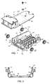
- Fig. 1 is an exploded view of an optical/electronic module and a controlled-deformation supporting structure of an electro-optical device according to the invention;
- Fig. 2 is a cross-sectional view, on a larger scale, along the plane indicated by II-II in Fig. 1;
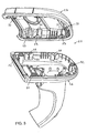
- Fig. 3 is an exploded view of a casing containing the module and the structure according to Fig. 1.
- Fig. 1 shows an optical/electronic module 1 and a supporting
structure 10 of an electro-optical device. The electro-optical device consists, for example, of a laser gun for reading optical codes. The module 1 comprises anoptical unit 3 and an electronic unit 40 (shown as a block in broken lines) mounted on aboard 2. Theoptical unit 3 comprises a laser (diode) source which emits a laser beam and optical components for focusing and driving the laser beam, which in turn comprise a movable mirror (not shown). The optical unit could contain a light source of the LED type and sensors of the CCD and CMOS type. The electronic unit comprises electronic components and a printed circuit formed on theboard 2 and connected to a cable by means of electrical connections (not shown). - The
board 2 has ahole 5 and twoeyelets 4, only one of which can be seen in Fig. 1. Thehole 5 is located close to one end of theboard 2 and theeyelets 4 are spaced from thehole 5 and are located in the vicinity of theoptical unit 3 on two longitudinal sides of theboard 2. - Fig. 1 also shows a
washer 6 and ascrew 7, the function of which will be illustrated further below. - The supporting
structure 10 comprises asupport frame 11 and four ring-shaped bearings 12. - The
frame 11 is formed in the manner of a shell and has abottom wall 13 andside walls 14. Thewall 13 is provided with a hollow stud 15 designed to penetrate into thehole 5 of theboard 2. By means of the stud 15, thewasher 6 and thescrew 7, theboard 2 is fixed to theframe 11.Lugs board 2 rests, are provided at the corners between thewall 13 and thewalls 14. Thewalls 14 are provided with resilient tongues 18 (Fig. 2) designed to co-operate with pairs ofunderlying lugs 116 situated in the vicinity of theoptical unit 3, in order to retain theboard 2 in theframe 11 in the vertical direction. Thewalls 14 are also provided withteeth 19, only one of which can be seen in Fig. 1 and which are inserted into theeyelets 4 of theboard 2 so as to retain the board in theframe 11 in the longitudinal direction. Eachwall 14 is further provided with a pair ofpins 20 for supporting thering bearings 12. Thebearings 12 could have other shapes: oval, rectangular, etc. - The
frame 11 is provided withopenings 113 which allow the cable with the electrical connections of the printed circuit to pass through. - The
frame 11 is made, for example, of a controlled-deformation material, such as a semi-rigid material, in particular a polymeric material chosen from the group comprising: nylon, acetal resins, polycarbonates and the like. These materials represent the best compromise between elasticity, rigidity and strength. - The
ring bearings 12 are made of visco-elastic material, for example rubber. - The
frame 11 may be made of a rigid material, such as a metallic material, or a substantially resilient material. In these latter cases, thebearings 12 are made of a material such as to provide thestructure 10 with the desired characteristics of capacity for absorption and dissipation of the impact energy. - The optical/electronic module 1 is mounted in the
frame 11, by splaying theside walls 14 and positioning theboard 2 on thelugs 16 so that the stud 15 enters into thehole 5 and theteeth 19 engage inside theeyelets 4. When thewalls 14 are released, theboard 2 is retained between thetongues 18 and the pairs ofunderlying tugs 116. Then, by simply screwing thescrew 7 into the stud 15 with the arrangement of thewasher 6 in between, theboard 2 is firmly fixed to theframe 11. Finally, thering bearings 12 are mounted on thepins 20. - The type of connection provided between the
board 2 and theframe 11 by means of theeyelets 4 and theteeth 19, thelugs tongues 18, allow relative movements of the board and the frame and prevent the deformations of the frame from being transmitted to the board. - Fig. 3 shows a
casing 25 in the form of a gun, which is designed to contain the group formed by the supportingstructure 10 and the optical/electronic module 1. The casing may have a banana shape or other shape. Thecasing 25 comprises abase 26 and acover 27 provided, respectively, with four half-seats 28 and four half-seats 29 for thepins 20 and thebearings 12. The half-seats wall portions base 26 has three through-holes 32 and thecover 27 has threeblind holes 33. Theholes 32 receive inside them screws, not shown, which are screwed into theholes 33 in order to fix thecover 27 to thebase 26. - In order to assemble the laser gun, the group formed by the
structure 10 and the module 1 is mounted inside thecover 27 so that thering bearings 12 are housed in the half-seats 29. Then thecover 27 is positioned on the base 26 so as to house thebearings 12 in the half-seats 28 and finally thecover 27 is screwed to thebase 26. - According to a variant, the support frame and the bearings may be moulded together and form a single body.
- According to another variant, the external casing and the support frame may be moulded together and connected by means of resilient bridge-pieces.
Claims (19)
- Portable electro-optical device comprising an optical/electronic module (1), an external casing (25) designed to contain said module (1) and a supporting structure (10) arranged between said module (1) and said external casing (25), said supporting structure (10) being connected to said external casing (25) and comprising a frame (11), the device further comprising a board (2) which is supported by said frame (11), the device being characterized in that said optical/electronic module (1) is mounted on said board (2) and in that said frame (11) comprises at least one element (19) designed to engage with at least one eyelet (4) formed on said board (2) for retaining said board (2) in said frame (11) in the longitudinal direction.
- Electro-optical device according to claim 1, characterized in that said frame (11) comprises bearing lugs (16; 116) for bearing said board (2) and at least one resilient tongue (18) designed to co-operate with at least one 1ug (116) in order to retain vertically said board (2) in said frame (11).
- Electro-optical device according to anyone of the previous claims, characterized in that said frame (11) comprises a bottom wall (13) and two side walls (14), said at least one element (19) being provided in at least one of said side walls (14).
- Electro-optical device according to anyone of the previous claims, characterized in that said supporting structure (10) is of the controlled-deformation type and is capable of dissipating energy resulting from impact stresses.
- Electro-optical device according to anyone of the previous claims, characterized in that said module (1) comprises an optical unit (3) and an electronic unit (40) both mounted on said board (2).
- Electro-optical device according to anyone of the previous claims, characterized in that said frame (11) is provided with pins (20) for connection to said external casing (25).
- Electro-optical device according to anyone of the previous claims, characterized in that said board (2) is provided with at least one hole (5) and said frame (11) is provided with at least one hollow stud (15) designed to penetrate into said hole (5) so as to be fixed to said board (2).
- Electro-optical device according to anyone of the previous claims, characterized in that said at least one element is in the form of a tooth (19).
- Electro-optical device according to anyone of the previous claims, characterized in that visco-elastic elements (12) are arranged between said support frame (11) and said external casing (25).
- Electro-optical device according to claim 9, characterized in that said visco-elastic elements (12) are rubber bearings.
- Electro-optical device according to claims 6 and 10, characterized in that said rubber bearings (12) are ring-shaped and are mounted on said pins (20).
- Electro-optical device according to claim 6, characterized in that said casing (25) comprises a base (26) and a cover (27), said base (26) and cover (27) being provided with respective half-seats (28, 29) designed to house said pins (20).
- Electro-optical device according to claims 10 and 12, characterized in that said half-seats (28, 29) are designed to house said bearings (12) as well.
- Electro-optical device according to anyone of the previous claims, characterized in that said support frame (11) is made of semi-rigid material.
- Electro-optical device according to claim 14, characterized in that said material is plastic and is chosen from the group comprising: nylon, acetal resins and polycarbonates.
- Electro-optical device according to anyone of the previous claims, characterized in that said support frame (11) is made of rigid material.
- Electro-optical device according to anyone of the previous claims, characterized in that said support frame (11) is made of substantially resilient material.
- Electro-optical device according to claim 5, characterized in that said optical unit (3) comprises a laser source which emits a laser beam and optical components for focusing and driving said laser beam.
- Electro-optical device according to claim 5, characterized in that said optical unit (3) comprises a diffused light source and a sensor of the CCD or CMOS type.
Priority Applications (4)
| Application Number | Priority Date | Filing Date | Title |
|---|---|---|---|
| EP98830611A EP0994436B1 (en) | 1998-10-15 | 1998-10-15 | Portable electro-optical device |
| AT98830611T ATE360857T1 (en) | 1998-10-15 | 1998-10-15 | PORTABLE ELECTRO-OPTICAL DEVICE |
| DE69837662T DE69837662T2 (en) | 1998-10-15 | 1998-10-15 | Portable electro-optical device |
| US09/362,988 US6442180B1 (en) | 1998-10-15 | 1999-07-30 | Portable electro-optical device |
Applications Claiming Priority (1)
| Application Number | Priority Date | Filing Date | Title |
|---|---|---|---|
| EP98830611A EP0994436B1 (en) | 1998-10-15 | 1998-10-15 | Portable electro-optical device |
Publications (2)
| Publication Number | Publication Date |
|---|---|
| EP0994436A1 EP0994436A1 (en) | 2000-04-19 |
| EP0994436B1 true EP0994436B1 (en) | 2007-04-25 |
Family
ID=8236833
Family Applications (1)
| Application Number | Title | Priority Date | Filing Date |
|---|---|---|---|
| EP98830611A Expired - Lifetime EP0994436B1 (en) | 1998-10-15 | 1998-10-15 | Portable electro-optical device |
Country Status (4)
| Country | Link |
|---|---|
| US (1) | US6442180B1 (en) |
| EP (1) | EP0994436B1 (en) |
| AT (1) | ATE360857T1 (en) |
| DE (1) | DE69837662T2 (en) |
Families Citing this family (8)
| Publication number | Priority date | Publication date | Assignee | Title |
|---|---|---|---|---|
| DE10106542B4 (en) * | 2001-02-13 | 2004-10-21 | Datasound Gmbh | Reading device for scanning a data strip containing coded information |
| US7012216B2 (en) * | 2002-02-08 | 2006-03-14 | Honeywell International | Hand-held laser welding wand having internal coolant and gas delivery conduits |
| US7550693B2 (en) * | 2005-02-04 | 2009-06-23 | Honeywell International Inc. | Hand-held laser welding wand with improved optical assembly serviceability features |
| DE102008009404B4 (en) * | 2008-02-15 | 2013-01-24 | Marson Technology Co., Ltd. | All-round radiating bar code reader |
| JP5809013B2 (en) * | 2011-10-14 | 2015-11-10 | 株式会社キーエンス | Optical information reader |
| USD734339S1 (en) * | 2013-12-05 | 2015-07-14 | Hand Held Products, Inc. | Indicia scanner |
| USD826234S1 (en) | 2016-04-11 | 2018-08-21 | Hand Held Products, Inc. | Indicia scanner |
| USD982585S1 (en) | 2013-12-05 | 2023-04-04 | Hand Held Products, Inc. | Indicia scanner |
Family Cites Families (2)
| Publication number | Priority date | Publication date | Assignee | Title |
|---|---|---|---|---|
| US5198651A (en) * | 1991-05-03 | 1993-03-30 | Symbol Technologies, Inc. | Laser diode device incorporating structure with integral scanning motor |
| US5543609A (en) * | 1994-10-28 | 1996-08-06 | Symbol Technologies, Inc. | Arrangement for and method of providing shock protection and vibration isolation for a scan module |
-
1998
- 1998-10-15 AT AT98830611T patent/ATE360857T1/en not_active IP Right Cessation
- 1998-10-15 EP EP98830611A patent/EP0994436B1/en not_active Expired - Lifetime
- 1998-10-15 DE DE69837662T patent/DE69837662T2/en not_active Expired - Lifetime
-
1999
- 1999-07-30 US US09/362,988 patent/US6442180B1/en not_active Expired - Lifetime
Also Published As
| Publication number | Publication date |
|---|---|
| ATE360857T1 (en) | 2007-05-15 |
| EP0994436A1 (en) | 2000-04-19 |
| DE69837662D1 (en) | 2007-06-06 |
| DE69837662T2 (en) | 2007-12-27 |
| US6442180B1 (en) | 2002-08-27 |
Similar Documents
| Publication | Publication Date | Title |
|---|---|---|
| EP0994436B1 (en) | Portable electro-optical device | |
| US5804809A (en) | Optical system for scanning and reading bar codes which is adapted to be configured in a hand held unit | |
| EP0600158B1 (en) | Light transmission apparatus for electro-optically coupling to a display panel for an electronic instrument | |
| US20140008088A1 (en) | Display Assemblies Having Integrated Display Covers and Light Pipes and Handheld Power Tools and Methods Including Same | |
| EP0930579A3 (en) | Ringscanner | |
| US7348536B2 (en) | Light grid with housing | |
| CN1391680A (en) | Imaging module for optical reader | |
| CA2143713C (en) | Portable scanner | |
| EP0973119A3 (en) | Optical reader having inclinable stage which mounts optical unit thereon | |
| EP0498366A2 (en) | System for scanning and reading symbols | |
| KR950006024Y1 (en) | Single lens reflex camera | |
| ES2075492T3 (en) | BLADE TREE SEPARATOR DEVICE FOR DOCUMENT DESTRUCTOR. | |
| JP2018045601A (en) | Portable device | |
| US11953809B2 (en) | Camera support structure and head-mounted display | |
| ES2078569T3 (en) | PROCEDURE FOR THE EQUIPMENT OF ELECTRICAL METERS WITH A RESPECTIVE EXTERNAL MODULE, AND INTERMEDIATE PART FOR THE PERFORMANCE OF THE PROCEDURE. | |
| JP2004032141A (en) | Camera module | |
| US11698184B2 (en) | Lighting device with rechargeable battery sandwich between printed circuit boards | |
| JPH10239611A (en) | Deflecting scanner | |
| US8235608B2 (en) | Camera module | |
| CN213457488U (en) | Lens module and electronic equipment | |
| EP0410565A2 (en) | Power supply assembly | |
| KR0168985B1 (en) | Laser light source units | |
| EP0649192A3 (en) | Electrical installation device with additional module. | |
| CN213581545U (en) | Lens module and electronic equipment | |
| JP2019039716A (en) | Power supply unit and laser surveying instrument |
Legal Events
| Date | Code | Title | Description |
|---|---|---|---|
| PUAI | Public reference made under article 153(3) epc to a published international application that has entered the european phase |
Free format text: ORIGINAL CODE: 0009012 |
|
| AK | Designated contracting states |
Kind code of ref document: A1 Designated state(s): AT BE CH DE DK ES FR GB IT LI NL PT SE |
|
| AX | Request for extension of the european patent |
Free format text: AL;LT;LV;MK;RO;SI |
|
| 17P | Request for examination filed |
Effective date: 20000325 |
|
| 17Q | First examination report despatched |
Effective date: 20000628 |
|
| AKX | Designation fees paid |
Free format text: AT BE CH DE DK ES FR GB IT LI NL PT SE |
|
| GRAP | Despatch of communication of intention to grant a patent |
Free format text: ORIGINAL CODE: EPIDOSNIGR1 |
|
| GRAS | Grant fee paid |
Free format text: ORIGINAL CODE: EPIDOSNIGR3 |
|
| GRAA | (expected) grant |
Free format text: ORIGINAL CODE: 0009210 |
|
| AK | Designated contracting states |
Kind code of ref document: B1 Designated state(s): AT BE CH DE DK ES FR GB IT LI NL PT SE |
|
| PG25 | Lapsed in a contracting state [announced via postgrant information from national office to epo] |
Ref country code: LI Free format text: LAPSE BECAUSE OF FAILURE TO SUBMIT A TRANSLATION OF THE DESCRIPTION OR TO PAY THE FEE WITHIN THE PRESCRIBED TIME-LIMIT Effective date: 20070425 Ref country code: CH Free format text: LAPSE BECAUSE OF FAILURE TO SUBMIT A TRANSLATION OF THE DESCRIPTION OR TO PAY THE FEE WITHIN THE PRESCRIBED TIME-LIMIT Effective date: 20070425 |
|
| REG | Reference to a national code |
Ref country code: GB Ref legal event code: FG4D |
|
| REG | Reference to a national code |
Ref country code: CH Ref legal event code: EP |
|
| REF | Corresponds to: |
Ref document number: 69837662 Country of ref document: DE Date of ref document: 20070606 Kind code of ref document: P |
|
| PG25 | Lapsed in a contracting state [announced via postgrant information from national office to epo] |
Ref country code: SE Free format text: LAPSE BECAUSE OF FAILURE TO SUBMIT A TRANSLATION OF THE DESCRIPTION OR TO PAY THE FEE WITHIN THE PRESCRIBED TIME-LIMIT Effective date: 20070725 |
|
| PG25 | Lapsed in a contracting state [announced via postgrant information from national office to epo] |
Ref country code: ES Free format text: LAPSE BECAUSE OF FAILURE TO SUBMIT A TRANSLATION OF THE DESCRIPTION OR TO PAY THE FEE WITHIN THE PRESCRIBED TIME-LIMIT Effective date: 20070805 |
|
| PG25 | Lapsed in a contracting state [announced via postgrant information from national office to epo] |
Ref country code: PT Free format text: LAPSE BECAUSE OF FAILURE TO SUBMIT A TRANSLATION OF THE DESCRIPTION OR TO PAY THE FEE WITHIN THE PRESCRIBED TIME-LIMIT Effective date: 20070925 |
|
| RAP2 | Party data changed (patent owner data changed or rights of a patent transferred) |
Owner name: DATALOGIC SCANNING GROUP S.R.L. |
|
| REG | Reference to a national code |
Ref country code: CH Ref legal event code: PL |
|
| NLV1 | Nl: lapsed or annulled due to failure to fulfill the requirements of art. 29p and 29m of the patents act | ||
| PG25 | Lapsed in a contracting state [announced via postgrant information from national office to epo] |
Ref country code: AT Free format text: LAPSE BECAUSE OF FAILURE TO SUBMIT A TRANSLATION OF THE DESCRIPTION OR TO PAY THE FEE WITHIN THE PRESCRIBED TIME-LIMIT Effective date: 20070425 |
|
| EN | Fr: translation not filed | ||
| PG25 | Lapsed in a contracting state [announced via postgrant information from national office to epo] |
Ref country code: BE Free format text: LAPSE BECAUSE OF FAILURE TO SUBMIT A TRANSLATION OF THE DESCRIPTION OR TO PAY THE FEE WITHIN THE PRESCRIBED TIME-LIMIT Effective date: 20070425 |
|
| PG25 | Lapsed in a contracting state [announced via postgrant information from national office to epo] |
Ref country code: NL Free format text: LAPSE BECAUSE OF FAILURE TO SUBMIT A TRANSLATION OF THE DESCRIPTION OR TO PAY THE FEE WITHIN THE PRESCRIBED TIME-LIMIT Effective date: 20070425 Ref country code: DK Free format text: LAPSE BECAUSE OF FAILURE TO SUBMIT A TRANSLATION OF THE DESCRIPTION OR TO PAY THE FEE WITHIN THE PRESCRIBED TIME-LIMIT Effective date: 20070425 |
|
| PLBE | No opposition filed within time limit |
Free format text: ORIGINAL CODE: 0009261 |
|
| STAA | Information on the status of an ep patent application or granted ep patent |
Free format text: STATUS: NO OPPOSITION FILED WITHIN TIME LIMIT |
|
| 26N | No opposition filed |
Effective date: 20080128 |
|
| PG25 | Lapsed in a contracting state [announced via postgrant information from national office to epo] |
Ref country code: IT Free format text: LAPSE BECAUSE OF FAILURE TO SUBMIT A TRANSLATION OF THE DESCRIPTION OR TO PAY THE FEE WITHIN THE PRESCRIBED TIME-LIMIT Effective date: 20070425 Ref country code: FR Free format text: LAPSE BECAUSE OF FAILURE TO SUBMIT A TRANSLATION OF THE DESCRIPTION OR TO PAY THE FEE WITHIN THE PRESCRIBED TIME-LIMIT Effective date: 20071221 |
|
| PG25 | Lapsed in a contracting state [announced via postgrant information from national office to epo] |
Ref country code: FR Free format text: LAPSE BECAUSE OF FAILURE TO SUBMIT A TRANSLATION OF THE DESCRIPTION OR TO PAY THE FEE WITHIN THE PRESCRIBED TIME-LIMIT Effective date: 20070425 |
|
| PGFP | Annual fee paid to national office [announced via postgrant information from national office to epo] |
Ref country code: DE Payment date: 20151022 Year of fee payment: 18 Ref country code: GB Payment date: 20151021 Year of fee payment: 18 |
|
| REG | Reference to a national code |
Ref country code: DE Ref legal event code: R119 Ref document number: 69837662 Country of ref document: DE |
|
| GBPC | Gb: european patent ceased through non-payment of renewal fee |
Effective date: 20161015 |
|
| PG25 | Lapsed in a contracting state [announced via postgrant information from national office to epo] |
Ref country code: DE Free format text: LAPSE BECAUSE OF NON-PAYMENT OF DUE FEES Effective date: 20170503 Ref country code: GB Free format text: LAPSE BECAUSE OF NON-PAYMENT OF DUE FEES Effective date: 20161015 |