EP0993692B1 - Excimer laser with magnetic bearings supporting fan - Google Patents
Excimer laser with magnetic bearings supporting fan Download PDFInfo
- Publication number
- EP0993692B1 EP0993692B1 EP98931615A EP98931615A EP0993692B1 EP 0993692 B1 EP0993692 B1 EP 0993692B1 EP 98931615 A EP98931615 A EP 98931615A EP 98931615 A EP98931615 A EP 98931615A EP 0993692 B1 EP0993692 B1 EP 0993692B1
- Authority
- EP
- European Patent Office
- Prior art keywords
- laser
- gas
- magnetic bearings
- fan
- bearings
- Prior art date
- Legal status (The legal status is an assumption and is not a legal conclusion. Google has not performed a legal analysis and makes no representation as to the accuracy of the status listed.)
- Revoked
Links
- 239000007789 gas Substances 0.000 claims description 38
- 238000007789 sealing Methods 0.000 claims description 7
- 229910052731 fluorine Inorganic materials 0.000 claims description 6
- 239000011737 fluorine Substances 0.000 claims description 6
- XKRFYHLGVUSROY-UHFFFAOYSA-N Argon Chemical compound [Ar] XKRFYHLGVUSROY-UHFFFAOYSA-N 0.000 claims description 4
- 229910052756 noble gas Inorganic materials 0.000 claims description 3
- 229910052786 argon Inorganic materials 0.000 claims description 2
- 229910052743 krypton Inorganic materials 0.000 claims description 2
- DNNSSWSSYDEUBZ-UHFFFAOYSA-N krypton atom Chemical compound [Kr] DNNSSWSSYDEUBZ-UHFFFAOYSA-N 0.000 claims description 2
- 229910052754 neon Inorganic materials 0.000 claims description 2
- GKAOGPIIYCISHV-UHFFFAOYSA-N neon atom Chemical compound [Ne] GKAOGPIIYCISHV-UHFFFAOYSA-N 0.000 claims description 2
- 230000035939 shock Effects 0.000 claims description 2
- 229910052736 halogen Inorganic materials 0.000 claims 2
- 150000002367 halogens Chemical class 0.000 claims 2
- PXGOKWXKJXAPGV-UHFFFAOYSA-N Fluorine Chemical compound FF PXGOKWXKJXAPGV-UHFFFAOYSA-N 0.000 claims 1
- 230000004936 stimulating effect Effects 0.000 claims 1
- YCKRFDGAMUMZLT-UHFFFAOYSA-N Fluorine atom Chemical compound [F] YCKRFDGAMUMZLT-UHFFFAOYSA-N 0.000 description 5
- XEEYBQQBJWHFJM-UHFFFAOYSA-N Iron Chemical compound [Fe] XEEYBQQBJWHFJM-UHFFFAOYSA-N 0.000 description 4
- 238000005461 lubrication Methods 0.000 description 4
- 238000011109 contamination Methods 0.000 description 3
- 229910052742 iron Inorganic materials 0.000 description 2
- 238000004804 winding Methods 0.000 description 2
- 229910000838 Al alloy Inorganic materials 0.000 description 1
- 241000555745 Sciuridae Species 0.000 description 1
- 230000003321 amplification Effects 0.000 description 1
- 230000001351 cycling effect Effects 0.000 description 1
- 230000000694 effects Effects 0.000 description 1
- 230000007613 environmental effect Effects 0.000 description 1
- 150000002505 iron Chemical class 0.000 description 1
- 238000001459 lithography Methods 0.000 description 1
- 238000012423 maintenance Methods 0.000 description 1
- 238000000034 method Methods 0.000 description 1
- 238000012986 modification Methods 0.000 description 1
- 230000004048 modification Effects 0.000 description 1
- 238000003199 nucleic acid amplification method Methods 0.000 description 1
- 230000010355 oscillation Effects 0.000 description 1
Images



Classifications
-
- G—PHYSICS
- G03—PHOTOGRAPHY; CINEMATOGRAPHY; ANALOGOUS TECHNIQUES USING WAVES OTHER THAN OPTICAL WAVES; ELECTROGRAPHY; HOLOGRAPHY
- G03F—PHOTOMECHANICAL PRODUCTION OF TEXTURED OR PATTERNED SURFACES, e.g. FOR PRINTING, FOR PROCESSING OF SEMICONDUCTOR DEVICES; MATERIALS THEREFOR; ORIGINALS THEREFOR; APPARATUS SPECIALLY ADAPTED THEREFOR
- G03F7/00—Photomechanical, e.g. photolithographic, production of textured or patterned surfaces, e.g. printing surfaces; Materials therefor, e.g. comprising photoresists; Apparatus specially adapted therefor
- G03F7/70—Microphotolithographic exposure; Apparatus therefor
- G03F7/70483—Information management; Active and passive control; Testing; Wafer monitoring, e.g. pattern monitoring
- G03F7/7055—Exposure light control in all parts of the microlithographic apparatus, e.g. pulse length control or light interruption
- G03F7/70575—Wavelength control, e.g. control of bandwidth, multiple wavelength, selection of wavelength or matching of optical components to wavelength
-
- F—MECHANICAL ENGINEERING; LIGHTING; HEATING; WEAPONS; BLASTING
- F16—ENGINEERING ELEMENTS AND UNITS; GENERAL MEASURES FOR PRODUCING AND MAINTAINING EFFECTIVE FUNCTIONING OF MACHINES OR INSTALLATIONS; THERMAL INSULATION IN GENERAL
- F16C—SHAFTS; FLEXIBLE SHAFTS; ELEMENTS OR CRANKSHAFT MECHANISMS; ROTARY BODIES OTHER THAN GEARING ELEMENTS; BEARINGS
- F16C32/00—Bearings not otherwise provided for
- F16C32/04—Bearings not otherwise provided for using magnetic or electric supporting means
- F16C32/0406—Magnetic bearings
- F16C32/044—Active magnetic bearings
- F16C32/047—Details of housings; Mounting of active magnetic bearings
-
- H—ELECTRICITY
- H01—ELECTRIC ELEMENTS
- H01S—DEVICES USING THE PROCESS OF LIGHT AMPLIFICATION BY STIMULATED EMISSION OF RADIATION [LASER] TO AMPLIFY OR GENERATE LIGHT; DEVICES USING STIMULATED EMISSION OF ELECTROMAGNETIC RADIATION IN WAVE RANGES OTHER THAN OPTICAL
- H01S3/00—Lasers, i.e. devices using stimulated emission of electromagnetic radiation in the infrared, visible or ultraviolet wave range
- H01S3/02—Constructional details
- H01S3/03—Constructional details of gas laser discharge tubes
- H01S3/036—Means for obtaining or maintaining the desired gas pressure within the tube, e.g. by gettering, replenishing; Means for circulating the gas, e.g. for equalising the pressure within the tube
-
- H—ELECTRICITY
- H01—ELECTRIC ELEMENTS
- H01S—DEVICES USING THE PROCESS OF LIGHT AMPLIFICATION BY STIMULATED EMISSION OF RADIATION [LASER] TO AMPLIFY OR GENERATE LIGHT; DEVICES USING STIMULATED EMISSION OF ELECTROMAGNETIC RADIATION IN WAVE RANGES OTHER THAN OPTICAL
- H01S3/00—Lasers, i.e. devices using stimulated emission of electromagnetic radiation in the infrared, visible or ultraviolet wave range
- H01S3/02—Constructional details
- H01S3/04—Arrangements for thermal management
- H01S3/041—Arrangements for thermal management for gas lasers
-
- H—ELECTRICITY
- H01—ELECTRIC ELEMENTS
- H01S—DEVICES USING THE PROCESS OF LIGHT AMPLIFICATION BY STIMULATED EMISSION OF RADIATION [LASER] TO AMPLIFY OR GENERATE LIGHT; DEVICES USING STIMULATED EMISSION OF ELECTROMAGNETIC RADIATION IN WAVE RANGES OTHER THAN OPTICAL
- H01S3/00—Lasers, i.e. devices using stimulated emission of electromagnetic radiation in the infrared, visible or ultraviolet wave range
- H01S3/14—Lasers, i.e. devices using stimulated emission of electromagnetic radiation in the infrared, visible or ultraviolet wave range characterised by the material used as the active medium
- H01S3/22—Gases
- H01S3/223—Gases the active gas being polyatomic, i.e. containing two or more atoms
- H01S3/225—Gases the active gas being polyatomic, i.e. containing two or more atoms comprising an excimer or exciplex
Definitions
- This invention relates to gas lasers and, in particular, to high repetition rate electric discharge gas lasers.
- Electric discharge gas lasers are well known and have been available since soon after lasers were invented in the 1960s.
- a high voltage discharge between two electrodes excites a gaseous gain medium.
- a resonance cavity containing the gain medium permit stimulated amplification of light which is then extracted from the cavity in the form of a laser beam.
- These electric discharge gas lasers may be operated in a continuous or pulse mode.
- Excimer lasers are a particular type of electric gas discharge laser and have been known as such since the mid 1970s.
- a description of an excimer laser, useful for integrated circuit lithography, is described in U.S. Patent No. 5,023,884 issued June 11, 1991 entitled "Compact Excimer Laser.”
- the excimer laser described in Patent '884 is a high repetition rate pulse laser.
- the principal elements of the laser 10 are shown in FIG. 1 which correspond to FIG. 1 in Patent '884.
- These high repetition rate lasers are usually provided with a gas circulation system which replaces the gas in the region between the electrodes between each pulse.
- a gas circulation system which replaces the gas in the region between the electrodes between each pulse.
- this is done with a long squirrel-cage type fan 46, having blades 48 as shown in FIG. 1 and FIG. 2 which is FIG 7 in Patent '884.
- the fan is slightly longer than the electrodes 18 and 20 and provides sufficient circulation so that at pulse rates between 100 to 1000 Hz, the gas between the electrodes is cleared between pulses.
- the shaft 130 of fan 46 is supported by two bearings 132 as shown in FIG. 3 which is FIG. 9 of Patent '884.
- the gas used in the laser contains fluorine which is extremely reactive.
- the fan rotor driving fan shaft 130 is sealed, within the same environmental system provided by housing structure members 12 and 14, by sealing member 136 as explained at column 9, line 45 of Patent '884, and the motor stator 140 is outside sealing member 136 and thus protected from the corrosive action of the fluorine gas.
- bearing 132 is subjected to the corrosive action of the chamber gas as is any lubrication used in the bearing. In addition, bearing lubrication can contaminate the gas.
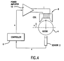
- FIG. 4 A typical prior art active radial bearing is described in FIG. 4.
- Sensor 2 senses the position of soft iron rotor 4 and sends a signal to controller 6 which controls the current in electromagnet 8 with power amplifier 10 in order to produce the precise magnetic field needed to balance rotor 4 in a desired position.
- the present invention provides an electric discharge gas laser having a laser cavity in which is contained a laser gas and a fan for circulating the laser gas.
- the fan is supported by an active magnetic bearing system and driven by a brushless DC motor in which the rotor of the motor and the rotors of at least two bearings are sealed within the gas environment of the laser cavity and the motor stator and the coils of the bearing magnets are located outside the gas environment.
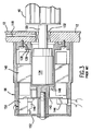
- FIG. 5 is a drawing showing important features of a preferred embodiment of the present invention.
- This drawing shows a fan system for gas circulation of an excimer laser of the type described in detail in U.S. Patent '884.
- This gas is comprised of fluorine, a buffer gas, neon, and a noble gas which could be either krypton or argon.
- rotor 134 is located on the end of shaft 130, with rotor 134 driving shaft 130, and thereby 26-inch fan 46, the central portion of which has been sectioned out in FIG. 5.
- stator 140 Surrounding the end of rotor 134 and sealing member 136 is stator 140 which is a series of windings.
- the stator 140 and rotor 134 together form a brushless DC motor which operates basically in the normal manner.
- the major difference between a normal brushless DC motor and this motor is the use of sealing member 136 located between the stator and the rotor so that the rotor is sealed relative to the stator 140.
- This arrangement permits the DC motor to drive fan 46 without the use of a rotating seal in the same manner as described in Patent '884.
- the motor also includes circuit board 142, power input connection 144,and a Hall detector 146 as explained in Patent '884.
- This embodiment of the present invention includes two radial magnetic bearings 120 and 22 supporting each end of shaft 130 of fan 46.
- the axial positioning of shaft 130 is provided by thrust bearing system 24.
- Radial bearings 120 and 22 each consist of four electromagnets 26 (two of which are shown in FIG. 5).
- the electromagnets are positioned at radial positions of 45°, 135°, 225° and 315°.
- the rotor 28 and stator elements are made of soft laminated iron.
- the electromagnets are very similar to the brushless DC motor discussed above. However, the function of the electromagnets is to hold the fan shaft in its proper radial position rather than rotate it.
- the electromagnets are preferably energized with a constant bias current (about half the maximum current which is symmetrically perturbed by a control current to produce dynamic control force).
- the fixed bias current provides a linearization of the magnetic forces produced by the bearings.
- Radial position sensors 32, 90° apart, aligned with the electromagnets provide position information to a control unit (not shown) which controls the current to the electromagnets in accordance with well known techniques.
- Thrust bearing system 24 provides the axial stability for shaft 130.
- the thrust bearing in this embodiment consist of two coils each applying attractive force to soft iron tab-unit 30 based on position information provided to the control unit (not shown) by axial position sensor 34.
- the rotor cavities at both ends of the fan shaft 130 are sealed by sealing members 136 and 36 and O-ring seals 138.
- the windings of motor unit 140 and electromagnets in bearings 120, 22 and 24 are protected from the corrosive fluorine gas in the laser chamber.
- the fan is a 26" long axial monolithic fan made from 9 identical cylindrical (hollow) segments of 2.3" long. Each segment is made of two rings/flanges with 3.75" OD and 2.75" ID. Between these rings lies 23 vanes/blades around 360° . The vanes are 2.3" long, 0.5" wide (curved) and 0.03" thick. The fan is made with aluminum alloy and weighs 1.5 lbs. Final weight for other considerations may go up to 2.0 lbs. The preferred speed of the fan is 3300 RPM to 5000 RPM.
- the fan operates at speeds of 3000 RPM to 5000 RPM in a laser gas environment with a fluorine content of about 0.1% at temperatures of about 60°C.
- the inventors expect at least 30,000 hours of trouble-free operation with a 95% confidence level and 10,000 hours of operation with a 99% confidence level.
- Prior art blowers typically operate at a constant speed such as 3800 RPM.
- the present invention will operate at speeds up to 5000 RPM or greater.
- the speed is continuously or periodically automatically cycled, for example, from 4000 RPM to 5000 RPM, in order to provide better mixing of the chamber gas.
- Automatic cycling of fan speed may also be utilized to avoid buildup of oscillations in the long fan.
- the speed of the fan can also be controlled, if necessary, from the information sent by a strategically located sensor to the controller. This is helpful if and when the rotating fan parts come too close to the parts of other components in the chamber. Although there are many other reasons to control and/or vary the speed of the fan, the one to reduce/control the effects of acoustic and/or shock waves are of significant importance in laser operations.
Landscapes
- Physics & Mathematics (AREA)
- Electromagnetism (AREA)
- Engineering & Computer Science (AREA)
- Plasma & Fusion (AREA)
- Optics & Photonics (AREA)
- General Physics & Mathematics (AREA)
- General Engineering & Computer Science (AREA)
- Mechanical Engineering (AREA)
- Lasers (AREA)
- Structures Of Non-Positive Displacement Pumps (AREA)
- Magnetic Bearings And Hydrostatic Bearings (AREA)
Abstract
Description
- This invention relates to gas lasers and, in particular, to high repetition rate electric discharge gas lasers.
- Electric discharge gas lasers are well known and have been available since soon after lasers were invented in the 1960s. A high voltage discharge between two electrodes excites a gaseous gain medium. A resonance cavity containing the gain medium permit stimulated amplification of light which is then extracted from the cavity in the form of a laser beam. These electric discharge gas lasers may be operated in a continuous or pulse mode.
- Excimer lasers are a particular type of electric gas discharge laser and have been known as such since the mid 1970s. A description of an excimer laser, useful for integrated circuit lithography, is described in
U.S. Patent No. 5,023,884 issued June 11, 1991 entitled "Compact Excimer Laser." The excimer laser described in Patent '884 is a high repetition rate pulse laser. The principal elements of thelaser 10 are shown in FIG. 1 which correspond to FIG. 1 in Patent '884. Thedischarges 22 are between two long (about 23 inches)electrodes cage type fan 46, havingblades 48 as shown in FIG. 1 and FIG. 2 which is FIG 7 in Patent '884. The fan is slightly longer than theelectrodes shaft 130 offan 46 is supported by twobearings 132 as shown in FIG. 3 which is FIG. 9 of Patent '884. The gas used in the laser contains fluorine which is extremely reactive. The fan rotordriving fan shaft 130 is sealed, within the same environmental system provided byhousing structure members member 136 as explained at column 9, line 45 of Patent '884, and themotor stator 140 is outside sealingmember 136 and thus protected from the corrosive action of the fluorine gas. However,bearing 132 is subjected to the corrosive action of the chamber gas as is any lubrication used in the bearing. In addition, bearing lubrication can contaminate the gas. - Active magnetic bearings have been well known for many years. Such systems were built as early as 1938, and they are used in many industrial applications today. Known advantages of these bearings include long life, reduced maintenance and small bearing losses, and no lubrication is required which eliminates a source of contamination.
- A typical prior art active radial bearing is described in FIG. 4.
Sensor 2 senses the position of soft iron rotor 4 and sends a signal to controller 6 which controls the current in electromagnet 8 withpower amplifier 10 in order to produce the precise magnetic field needed to balance rotor 4 in a desired position. - There is a need to increase the pulse repetition of gas discharge lasers, including the type of excimer lasers described in U.S. Patent '884 and a corresponding need for higher fan speed. This increases the burden of fan shaft bearings, requiring better bearings and more powerful fan motors. There is also the need to reduce sources of contamination in high repetition rate gas discharge lasers.
- The present invention according to claim 1 provides an electric discharge gas laser having a laser cavity in which is contained a laser gas and a fan for circulating the laser gas. The fan is supported by an active magnetic bearing system and driven by a brushless DC motor in which the rotor of the motor and the rotors of at least two bearings are sealed within the gas environment of the laser cavity and the motor stator and the coils of the bearing magnets are located outside the gas environment.
-
- FIG. 1 shows a prior art laser system.
- FIG. 2 shows the location of a squirrel cage fan in the FIG. 1 laser.
- FIG. 3 shows a brushless DC motor for driving the fan.
- FIG. 4 demonstrates the functioning of a prior art active radial magnetic bearing system.
- FIG. 5 is a drawing of a preferred embodiment of the present invention.
- Preferred embodiments of the present invention can be described by reference to the drawings.
- FIG. 5 is a drawing showing important features of a preferred embodiment of the present invention. This drawing shows a fan system for gas circulation of an excimer laser of the type described in detail in U.S. Patent '884. This gas is comprised of fluorine, a buffer gas, neon, and a noble gas which could be either krypton or argon. As in the prior art unit,
rotor 134 is located on the end ofshaft 130, withrotor 134driving shaft 130, and thereby 26-inch fan 46, the central portion of which has been sectioned out in FIG. 5. Surrounding the end ofrotor 134 and sealingmember 136 isstator 140 which is a series of windings. Thestator 140 androtor 134 together form a brushless DC motor which operates basically in the normal manner. The major difference between a normal brushless DC motor and this motor is the use of sealingmember 136 located between the stator and the rotor so that the rotor is sealed relative to thestator 140. This arrangement permits the DC motor to drivefan 46 without the use of a rotating seal in the same manner as described in Patent '884. The motor also includescircuit board 142,power input connection 144,and aHall detector 146 as explained in Patent '884. - This embodiment of the present invention includes two radial
magnetic bearings shaft 130 offan 46. The axial positioning ofshaft 130 is provided by thrust bearingsystem 24.Radial bearings rotor 28 and stator elements are made of soft laminated iron. In fact, the electromagnets are very similar to the brushless DC motor discussed above. However, the function of the electromagnets is to hold the fan shaft in its proper radial position rather than rotate it. The electromagnets are preferably energized with a constant bias current (about half the maximum current which is symmetrically perturbed by a control current to produce dynamic control force). The fixed bias current provides a linearization of the magnetic forces produced by the bearings.Radial position sensors 32, 90° apart, aligned with the electromagnets provide position information to a control unit (not shown) which controls the current to the electromagnets in accordance with well known techniques.Thrust bearing system 24 provides the axial stability forshaft 130. The thrust bearing in this embodiment consist of two coils each applying attractive force to soft iron tab-unit 30 based on position information provided to the control unit (not shown) by axial position sensor 34. - The rotor cavities at both ends of the
fan shaft 130 are sealed by sealingmembers ring seals 138. Thus, the windings ofmotor unit 140 and electromagnets inbearings - In this preferred embodiment, the fan is a 26" long axial monolithic fan made from 9 identical cylindrical (hollow) segments of 2.3" long. Each segment is made of two rings/flanges with 3.75" OD and 2.75" ID. Between these rings lies 23 vanes/blades around 360° . The vanes are 2.3" long, 0.5" wide (curved) and 0.03" thick. The fan is made with aluminum alloy and weighs 1.5 lbs. Final weight for other considerations may go up to 2.0 lbs. The preferred speed of the fan is 3300 RPM to 5000 RPM.
- The fan operates at speeds of 3000 RPM to 5000 RPM in a laser gas environment with a fluorine content of about 0.1% at temperatures of about 60°C. With these bearings, the inventors expect at least 30,000 hours of trouble-free operation with a 95% confidence level and 10,000 hours of operation with a 99% confidence level.
- Advantages of the present invention over the prior art ball bearing supported fan are many. There is a substantial increase in bearing life. The active control of the magnet bearings of rotor position substantially eliminate vibration. Lubrication contamination problems are eliminated. The need for careful balancing of the fan is avoided.
- Prior art blowers typically operate at a constant speed such as 3800 RPM. The present invention will operate at speeds up to 5000 RPM or greater. In a preferred operating mode, the speed is continuously or periodically automatically cycled, for example, from 4000 RPM to 5000 RPM, in order to provide better mixing of the chamber gas. Automatic cycling of fan speed may also be utilized to avoid buildup of oscillations in the long fan.
- The speed of the fan can also be controlled, if necessary, from the information sent by a strategically located sensor to the controller. This is helpful if and when the rotating fan parts come too close to the parts of other components in the chamber. Although there are many other reasons to control and/or vary the speed of the fan, the one to reduce/control the effects of acoustic and/or shock waves are of significant importance in laser operations.
- While the invention has been described in connection with what is presently considered to be the preferred embodiments, it is to be understood that the invention is not limited to the disclosed embodiments, but on the contrary, covers various modifications and equivalents included within the scope of the following claims. For example, we have shown only one example of radial active magnetic bearings. Many alternate magnetic bearing designs are well known and can be adopted to gas discharge lasers using the concept disclosed herein. For example, radial bearings are available which also provide axial control which would eliminate the need for thrust bearings. Therefore, persons of ordinary skill in this field are to understand that all such equivalents are included within the scope of the claims.
Claims (13)
- An electric discharge gas laser comprisingA. a housing structure (12) having walls forming an internal laser cavity;B. a gas located within the laser cavity, said gas being capable of lasing action;C. a pair of elongated spaced electrodes (18, 20) located within the laser cavity and forming an electrical discharge region between the electrodes for stimulating gas within the discharge region to lasing action in accordance with an electrical discharge between the electrodes;D. a rotating fan (46) having a shaft (130) located within the laser cavity for circulating the gas through the discharge region:E. a brushless DC motor comprising a stator (140) and a rotor (134) for providing rotation to the fan;F. at least two magnetic bearings, each comprising stator and a rotor (28) and position sensors (32) for providing radial support to said shaft;G. said rotors (28) of said motor and said at least two magnetic bearings (120, 22, 24), each being coupled directly or indirectly to said shaft; andH. at least one sealing member (136, 36 38) interposed between said rotors (28) and said stators (140) to enclose said rotors with said sealing member sealed to the housing structure to have said rotors effectively sealed within the gas environment and the stators without the gas environment.
- A laser as in Claim 1 wherein at least one of said at least two magnetic bearings is a thrust bearing.
- A laser as in Claim 1 wherein at least one of said magnetic bearings is a radial bearing.
- A laser as in Claim 1 wherein at least one of said magnetic bearings is a conical bearing.
- A laser as in Claim 1 wherein said at least two magnetic bearings are two conical bearings.
- A laser as in Claim 1 wherein said at least two magnetic bearings are two radial bearings and two thrust bearings.
- A laser as in Claim 3 and further comprising an electronic fan control unit providing high speed active control to said radial magnetic bearings.
- A laser as in Claim 3 wherein at least one of said magnetic bearings is a thrust bearing and further comprising an electronic fan control unit providing high speed active control to said radial magnetic bearings and active control to said thrust bearing system and active control to said motor.
- A laser as in Claim 8 wherein said control unit is programmed to operate said fan at periodically varying speeds.
- A laser as in Claim 1 wherein said gas comprises a halogen and a noble gas and a buffer gas to provide an excimer laser.
- A laser as in Claim 10 wherein said halogen is fluorine, said buffer gas is neon and said noble gas is krypton or argon.
- A laser as in Claim 1 and further comprising an active control unit programmed to prevent contact by the rotating fan with other components in the laser cavity.
- A laser as in Claim 1 and further comprising a control unit programmed to minimize acoustic and/or shock wave disturbances within the gas.
Applications Claiming Priority (3)
| Application Number | Priority Date | Filing Date | Title |
|---|---|---|---|
| US08/893,904 US5848089A (en) | 1997-07-11 | 1997-07-11 | Excimer laser with magnetic bearings supporting fan |
| US893904 | 1997-07-11 | ||
| PCT/US1998/013271 WO1999003176A1 (en) | 1997-07-11 | 1998-06-26 | Excimer laser with magnetic bearings supporting fan |
Publications (3)
| Publication Number | Publication Date |
|---|---|
| EP0993692A1 EP0993692A1 (en) | 2000-04-19 |
| EP0993692A4 EP0993692A4 (en) | 2004-05-19 |
| EP0993692B1 true EP0993692B1 (en) | 2007-12-26 |
Family
ID=25402318
Family Applications (1)
| Application Number | Title | Priority Date | Filing Date |
|---|---|---|---|
| EP98931615A Revoked EP0993692B1 (en) | 1997-07-11 | 1998-06-26 | Excimer laser with magnetic bearings supporting fan |
Country Status (8)
| Country | Link |
|---|---|
| US (1) | US5848089A (en) |
| EP (1) | EP0993692B1 (en) |
| JP (1) | JP2981210B2 (en) |
| KR (1) | KR100504071B1 (en) |
| AU (1) | AU8169598A (en) |
| DE (1) | DE69838908T2 (en) |
| TW (1) | TW398103B (en) |
| WO (1) | WO1999003176A1 (en) |
Families Citing this family (40)
| Publication number | Priority date | Publication date | Assignee | Title |
|---|---|---|---|---|
| US6128323A (en) * | 1997-04-23 | 2000-10-03 | Cymer, Inc. | Reliable modular production quality narrow-band high REP rate excimer laser |
| US6757316B2 (en) * | 1999-12-27 | 2004-06-29 | Cymer, Inc. | Four KHz gas discharge laser |
| US6853653B2 (en) * | 1997-07-22 | 2005-02-08 | Cymer, Inc. | Laser spectral engineering for lithographic process |
| JP3930170B2 (en) | 1998-02-18 | 2007-06-13 | 株式会社荏原製作所 | Circulation fan device |
| US6477193B2 (en) * | 1998-07-18 | 2002-11-05 | Cymer, Inc. | Extreme repetition rate gas discharge laser with improved blower motor |
| AU5583999A (en) * | 1998-09-02 | 2000-03-21 | Visx Incorporated | Electromagnetic drive system and method for gas laser fans |
| JP2000138404A (en) * | 1998-10-29 | 2000-05-16 | Komatsu Ltd | A once-through fan for excimer laser equipment. |
| JP4033631B2 (en) * | 1998-11-30 | 2008-01-16 | 株式会社荏原製作所 | Discharge excitation excimer laser equipment |
| JP2000183436A (en) * | 1998-12-18 | 2000-06-30 | Komatsu Ltd | Excimer laser device |
| US6490304B1 (en) * | 1999-03-05 | 2002-12-03 | Ntn Corporation | Excimer laser device |
| US6026103A (en) * | 1999-04-13 | 2000-02-15 | Cymer, Inc. | Gas discharge laser with roller bearings and stable magnetic axial positioning |
| US6104735A (en) * | 1999-04-13 | 2000-08-15 | Cymer, Inc. | Gas discharge laser with magnetic bearings and magnetic reluctance centering for fan drive assembly |
| US6556600B2 (en) | 1999-09-27 | 2003-04-29 | Cymer, Inc. | Injection seeded F2 laser with centerline wavelength control |
| US6590922B2 (en) | 1999-09-27 | 2003-07-08 | Cymer, Inc. | Injection seeded F2 laser with line selection and discrimination |
| US6795474B2 (en) * | 2000-11-17 | 2004-09-21 | Cymer, Inc. | Gas discharge laser with improved beam path |
| JP3877912B2 (en) * | 1999-05-25 | 2007-02-07 | 株式会社荏原製作所 | Discharge excitation excimer laser equipment |
| JP2001077446A (en) * | 1999-09-07 | 2001-03-23 | Nsk Ltd | Excimer laser device |
| US6359922B1 (en) * | 1999-10-20 | 2002-03-19 | Cymer, Inc. | Single chamber gas discharge laser with line narrowed seed beam |
| JP2001111138A (en) * | 1999-10-04 | 2001-04-20 | Ebara Corp | Excimer laser device |
| EP2287721A3 (en) | 1999-11-02 | 2011-04-06 | Canon Kabushiki Kaisha | Print control method and apparatus |
| US6765946B2 (en) * | 2000-01-25 | 2004-07-20 | Cymer, Inc. | Fan for gas discharge laser |
| EP1119082A3 (en) * | 2000-01-18 | 2004-05-26 | Ushiodenki Kabushiki Kaisha | Cross-flow fan for discharge excited gas laser |
| JP2001210896A (en) * | 2000-01-28 | 2001-08-03 | Ebara Corp | Excimer laser device |
| US6847671B1 (en) | 2000-03-29 | 2005-01-25 | Lambda Physik Ag | Blower for gas laser |
| WO2001082423A1 (en) | 2000-04-26 | 2001-11-01 | Ebara Corporation | Excimer laser apparatus |
| JP2001352114A (en) * | 2000-06-08 | 2001-12-21 | Ebara Corp | Magnetic bearing device for excimer laser device |
| EP1188932A3 (en) | 2000-09-19 | 2003-05-02 | Ntn Corporation | Bearing structure for laser fan |
| US6839372B2 (en) * | 2000-11-17 | 2005-01-04 | Cymer, Inc. | Gas discharge ultraviolet laser with enclosed beam path with added oxidizer |
| JP2003056489A (en) * | 2001-08-21 | 2003-02-26 | Ntn Corp | Gas circulation fan for excimer laser equipment |
| EP1295910A1 (en) | 2001-09-25 | 2003-03-26 | Borealis GmbH | Insulating foam composition |
| JP2003106333A (en) * | 2001-09-28 | 2003-04-09 | Ntn Corp | Magnetic bearing device |
| US8379687B2 (en) | 2005-06-30 | 2013-02-19 | Cymer, Inc. | Gas discharge laser line narrowing module |
| CN100526992C (en) | 2005-07-01 | 2009-08-12 | 株式会社尼康 | Exposure apparatus, exposure method, device manufacturing method |
| US7321607B2 (en) * | 2005-11-01 | 2008-01-22 | Cymer, Inc. | External optics and chamber support system |
| US8814522B2 (en) | 2007-06-15 | 2014-08-26 | Cymer, Llc | Cross-flow fan impeller for a transversley excited, pulsed, gas discharge laser |
| JP6063199B2 (en) | 2012-10-15 | 2017-01-18 | ギガフォトン株式会社 | Discharge excitation type gas laser equipment |
| WO2016143135A1 (en) | 2015-03-12 | 2016-09-15 | ギガフォトン株式会社 | Discharge excited gas laser device |
| CN110447149B (en) * | 2017-04-18 | 2021-07-16 | 极光先进雷射株式会社 | Gas laser device and magnetic bearing control method |
| CN111879517B (en) * | 2020-08-31 | 2022-02-22 | 合肥工业大学 | Device and method for detecting bearing abrasion in canned motor pump |
| US12104602B2 (en) * | 2021-02-18 | 2024-10-01 | Levitronix Gmbh | Cross-flow fan |
Family Cites Families (11)
| Publication number | Priority date | Publication date | Assignee | Title |
|---|---|---|---|---|
| JPS61203688A (en) * | 1985-03-07 | 1986-09-09 | Mitsubishi Electric Corp | Gas circulation type laser oscillation device |
| EP0209625B1 (en) * | 1985-07-09 | 1990-10-24 | JAMES HOWDEN & COMPANY LIMITED | Gas circulator |
| US4891818A (en) * | 1987-08-31 | 1990-01-02 | Acculase, Inc. | Rare gas-halogen excimer laser |
| US5023884A (en) * | 1988-01-15 | 1991-06-11 | Cymer Laser Technologies | Compact excimer laser |
| US4959840A (en) * | 1988-01-15 | 1990-09-25 | Cymer Laser Technologies | Compact excimer laser including an electrode mounted in insulating relationship to wall of the laser |
| JPH01189974A (en) * | 1988-01-26 | 1989-07-31 | Fanuc Ltd | Laser oscillator |
| JPH0521866A (en) * | 1991-07-12 | 1993-01-29 | Komatsu Ltd | Gas laser equipment |
| US5377215A (en) * | 1992-11-13 | 1994-12-27 | Cymer Laser Technologies | Excimer laser |
| DE9215696U1 (en) * | 1992-11-18 | 1994-03-17 | Anton Piller GmbH & Co KG, 37520 Osterode | Power generation plant |
| JP3427571B2 (en) * | 1995-06-14 | 2003-07-22 | 松下電器産業株式会社 | High-speed axial-flow gas laser oscillator |
| CA2190697C (en) * | 1996-01-31 | 2000-07-25 | Donald Glenn Larson | Blower motor with adjustable timing |
-
1997
- 1997-07-11 US US08/893,904 patent/US5848089A/en not_active Expired - Lifetime
-
1998
- 1998-06-26 WO PCT/US1998/013271 patent/WO1999003176A1/en not_active Ceased
- 1998-06-26 KR KR10-2000-7000246A patent/KR100504071B1/en not_active Expired - Fee Related
- 1998-06-26 EP EP98931615A patent/EP0993692B1/en not_active Revoked
- 1998-06-26 AU AU81695/98A patent/AU8169598A/en not_active Abandoned
- 1998-06-26 DE DE69838908T patent/DE69838908T2/en not_active Expired - Fee Related
- 1998-07-04 TW TW087110855A patent/TW398103B/en not_active IP Right Cessation
- 1998-07-13 JP JP10197140A patent/JP2981210B2/en not_active Expired - Lifetime
Also Published As
| Publication number | Publication date |
|---|---|
| JPH1187810A (en) | 1999-03-30 |
| EP0993692A1 (en) | 2000-04-19 |
| JP2981210B2 (en) | 1999-11-22 |
| US5848089A (en) | 1998-12-08 |
| EP0993692A4 (en) | 2004-05-19 |
| KR100504071B1 (en) | 2005-07-27 |
| WO1999003176A1 (en) | 1999-01-21 |
| DE69838908T2 (en) | 2008-04-30 |
| AU8169598A (en) | 1999-02-08 |
| KR20010021688A (en) | 2001-03-15 |
| DE69838908D1 (en) | 2008-02-07 |
| TW398103B (en) | 2000-07-11 |
Similar Documents
| Publication | Publication Date | Title |
|---|---|---|
| US5848089A (en) | Excimer laser with magnetic bearings supporting fan | |
| US6104735A (en) | Gas discharge laser with magnetic bearings and magnetic reluctance centering for fan drive assembly | |
| US6026103A (en) | Gas discharge laser with roller bearings and stable magnetic axial positioning | |
| US5157295A (en) | Under-the-hub disk drive spin motor | |
| WO2000032257A1 (en) | Active magnetic bearing system for blood pump | |
| EP0325652B1 (en) | Gas laser having a piezoelectric fan | |
| KR102486142B1 (en) | Reversing Shaft Electric Motor Assembly | |
| US6337872B1 (en) | Once through fan for excimer laser apparatus | |
| KR100708925B1 (en) | Discharge Pumped Excimer Laser Device | |
| JP2001077446A (en) | Excimer laser device | |
| JPS6399742A (en) | Magnetic bearing integrating type motor | |
| JP2003120582A (en) | Control device for molecular pump and molecular pump device | |
| JP2000216460A (en) | Excimer laser device | |
| KR20010039984A (en) | Excimer laser apparatus | |
| JP2000133860A (en) | Gas circulation device and laser oscillation device | |
| JP2001177167A (en) | Laser gas circulation mechanism of gas laser device | |
| JP2002204013A (en) | Excimer laser device | |
| JPH08338392A (en) | Vacuum pump device | |
| JPH04109559U (en) | Laser gas blower | |
| JPH04191518A (en) | Magnetic bearing device for rotating body | |
| JPS63227988A (en) | Blower device | |
| JPH01205584A (en) | Laser emission device | |
| WO2000013272A1 (en) | Electromagnetic drive system and method for gas laser fans | |
| JPH0615883B2 (en) | Magnetic bearing | |
| JP2002089489A (en) | Structure of once-through fan for excimer laser device |
Legal Events
| Date | Code | Title | Description |
|---|---|---|---|
| PUAI | Public reference made under article 153(3) epc to a published international application that has entered the european phase |
Free format text: ORIGINAL CODE: 0009012 |
|
| 17P | Request for examination filed |
Effective date: 19991229 |
|
| AK | Designated contracting states |
Kind code of ref document: A1 Designated state(s): BE DE ES FR GB IT LU NL |
|
| RAP1 | Party data changed (applicant data changed or rights of an application transferred) |
Owner name: CYMER, INC. |
|
| A4 | Supplementary search report drawn up and despatched |
Effective date: 20040406 |
|
| RIC1 | Information provided on ipc code assigned before grant |
Ipc: 7H 01S 3/036 A |
|
| GRAP | Despatch of communication of intention to grant a patent |
Free format text: ORIGINAL CODE: EPIDOSNIGR1 |
|
| GRAS | Grant fee paid |
Free format text: ORIGINAL CODE: EPIDOSNIGR3 |
|
| GRAA | (expected) grant |
Free format text: ORIGINAL CODE: 0009210 |
|
| AK | Designated contracting states |
Kind code of ref document: B1 Designated state(s): BE DE ES FR GB IT LU NL |
|
| REG | Reference to a national code |
Ref country code: GB Ref legal event code: FG4D |
|
| REF | Corresponds to: |
Ref document number: 69838908 Country of ref document: DE Date of ref document: 20080207 Kind code of ref document: P |
|
| PG25 | Lapsed in a contracting state [announced via postgrant information from national office to epo] |
Ref country code: ES Free format text: LAPSE BECAUSE OF FAILURE TO SUBMIT A TRANSLATION OF THE DESCRIPTION OR TO PAY THE FEE WITHIN THE PRESCRIBED TIME-LIMIT Effective date: 20080406 |
|
| ET | Fr: translation filed | ||
| PG25 | Lapsed in a contracting state [announced via postgrant information from national office to epo] |
Ref country code: BE Free format text: LAPSE BECAUSE OF FAILURE TO SUBMIT A TRANSLATION OF THE DESCRIPTION OR TO PAY THE FEE WITHIN THE PRESCRIBED TIME-LIMIT Effective date: 20071226 |
|
| PLBI | Opposition filed |
Free format text: ORIGINAL CODE: 0009260 |
|
| PGFP | Annual fee paid to national office [announced via postgrant information from national office to epo] |
Ref country code: NL Payment date: 20080624 Year of fee payment: 11 Ref country code: DE Payment date: 20080731 Year of fee payment: 11 |
|
| PLAX | Notice of opposition and request to file observation + time limit sent |
Free format text: ORIGINAL CODE: EPIDOSNOBS2 |
|
| 26 | Opposition filed |
Opponent name: SOCIETE DE MECANIQUE MAGNETIQUE S.A. Effective date: 20080926 |
|
| PGFP | Annual fee paid to national office [announced via postgrant information from national office to epo] |
Ref country code: FR Payment date: 20080617 Year of fee payment: 11 |
|
| NLR1 | Nl: opposition has been filed with the epo |
Opponent name: SOCIETE DE MECANIQUE MAGNETIQUE S.A. |
|
| GBPC | Gb: european patent ceased through non-payment of renewal fee |
Effective date: 20080626 |
|
| PLAF | Information modified related to communication of a notice of opposition and request to file observations + time limit |
Free format text: ORIGINAL CODE: EPIDOSCOBS2 |
|
| PLBB | Reply of patent proprietor to notice(s) of opposition received |
Free format text: ORIGINAL CODE: EPIDOSNOBS3 |
|
| PG25 | Lapsed in a contracting state [announced via postgrant information from national office to epo] |
Ref country code: GB Free format text: LAPSE BECAUSE OF NON-PAYMENT OF DUE FEES Effective date: 20080626 |
|
| PLAB | Opposition data, opponent's data or that of the opponent's representative modified |
Free format text: ORIGINAL CODE: 0009299OPPO |
|
| RDAF | Communication despatched that patent is revoked |
Free format text: ORIGINAL CODE: EPIDOSNREV1 |
|
| NLV4 | Nl: lapsed or anulled due to non-payment of the annual fee |
Effective date: 20100101 |
|
| RDAG | Patent revoked |
Free format text: ORIGINAL CODE: 0009271 |
|
| STAA | Information on the status of an ep patent application or granted ep patent |
Free format text: STATUS: PATENT REVOKED |
|
| REG | Reference to a national code |
Ref country code: FR Ref legal event code: ST Effective date: 20100226 |
|
| 27W | Patent revoked |
Effective date: 20091213 |
|
| PG25 | Lapsed in a contracting state [announced via postgrant information from national office to epo] |
Ref country code: FR Free format text: LAPSE BECAUSE OF NON-PAYMENT OF DUE FEES Effective date: 20090630 |
|
| PG25 | Lapsed in a contracting state [announced via postgrant information from national office to epo] |
Ref country code: LU Free format text: LAPSE BECAUSE OF NON-PAYMENT OF DUE FEES Effective date: 20080626 |
|
| PG25 | Lapsed in a contracting state [announced via postgrant information from national office to epo] |
Ref country code: IT Free format text: LAPSE BECAUSE OF NON-PAYMENT OF DUE FEES Effective date: 20080630 |