EP0993239B1 - X-ray apparatus - Google Patents
X-ray apparatus Download PDFInfo
- Publication number
- EP0993239B1 EP0993239B1 EP99203176A EP99203176A EP0993239B1 EP 0993239 B1 EP0993239 B1 EP 0993239B1 EP 99203176 A EP99203176 A EP 99203176A EP 99203176 A EP99203176 A EP 99203176A EP 0993239 B1 EP0993239 B1 EP 0993239B1
- Authority
- EP
- European Patent Office
- Prior art keywords
- ray
- control system
- exposure field
- organ
- aperture
- Prior art date
- Legal status (The legal status is an assumption and is not a legal conclusion. Google has not performed a legal analysis and makes no representation as to the accuracy of the status listed.)
- Expired - Lifetime
Links
- 210000000056 organ Anatomy 0.000 claims description 29
- 230000008859 change Effects 0.000 claims description 6
- 238000003384 imaging method Methods 0.000 claims description 3
- 238000001514 detection method Methods 0.000 claims 4
- 239000011159 matrix material Substances 0.000 claims 1
- 210000004072 lung Anatomy 0.000 description 6
- 238000000034 method Methods 0.000 description 5
- 210000000746 body region Anatomy 0.000 description 2
- 230000001419 dependent effect Effects 0.000 description 2
- 230000008569 process Effects 0.000 description 2
- 230000001276 controlling effect Effects 0.000 description 1
- 230000002596 correlated effect Effects 0.000 description 1
- 230000000875 corresponding effect Effects 0.000 description 1
- 230000006870 function Effects 0.000 description 1
- 230000002685 pulmonary effect Effects 0.000 description 1
- 238000002601 radiography Methods 0.000 description 1
- 230000004044 response Effects 0.000 description 1
- 230000007704 transition Effects 0.000 description 1
Images

Classifications
-
- A—HUMAN NECESSITIES
- A61—MEDICAL OR VETERINARY SCIENCE; HYGIENE
- A61B—DIAGNOSIS; SURGERY; IDENTIFICATION
- A61B6/00—Apparatus or devices for radiation diagnosis; Apparatus or devices for radiation diagnosis combined with radiation therapy equipment
- A61B6/54—Control of apparatus or devices for radiation diagnosis
- A61B6/542—Control of apparatus or devices for radiation diagnosis involving control of exposure
-
- A—HUMAN NECESSITIES
- A61—MEDICAL OR VETERINARY SCIENCE; HYGIENE
- A61B—DIAGNOSIS; SURGERY; IDENTIFICATION
- A61B6/00—Apparatus or devices for radiation diagnosis; Apparatus or devices for radiation diagnosis combined with radiation therapy equipment
- A61B6/06—Diaphragms
-
- G—PHYSICS
- G21—NUCLEAR PHYSICS; NUCLEAR ENGINEERING
- G21K—TECHNIQUES FOR HANDLING PARTICLES OR IONISING RADIATION NOT OTHERWISE PROVIDED FOR; IRRADIATION DEVICES; GAMMA RAY OR X-RAY MICROSCOPES
- G21K1/00—Arrangements for handling particles or ionising radiation, e.g. focusing or moderating
- G21K1/02—Arrangements for handling particles or ionising radiation, e.g. focusing or moderating using diaphragms, collimators
- G21K1/04—Arrangements for handling particles or ionising radiation, e.g. focusing or moderating using diaphragms, collimators using variable diaphragms, shutters, choppers
-
- A—HUMAN NECESSITIES
- A61—MEDICAL OR VETERINARY SCIENCE; HYGIENE
- A61B—DIAGNOSIS; SURGERY; IDENTIFICATION
- A61B6/00—Apparatus or devices for radiation diagnosis; Apparatus or devices for radiation diagnosis combined with radiation therapy equipment
- A61B6/08—Auxiliary means for directing the radiation beam to a particular spot, e.g. using light beams
Definitions
- the invention relates to an X-ray device with an X-ray recorder and an X-ray generator for supplying a cooperating with the X-ray radiograph X-ray and with an X-ray connected aperture unit with adjustable aperture for the purpose of specifying a recording field on an X-ray imager, wherein the aperture on the one hand by one of a Control system controlled drive unit and on the other hand adjustable by adjusting means for manually adjusting the aperture.
- X-ray devices of this type for making Bucky pictures are known. Film-film combinations of different formats are used as imagers, which are located in cassettes with dimensions adapted thereto.
- the examiner selects the cassette format required for the subsequent x-ray exposure and places the cassette in the x-ray device. This has a measuring device for detecting the cassette format.
- the control system then adjusts the aperture as a function of the measured cassette size so that the recording field corresponds to the cassette format or the format of the film therein. Manual adjustment of the recording field is only necessary with such X-ray devices if the examiner wants to restrict the field of view.
- X-ray detectors are used as imagers, which contain a plurality (eg 2000x2000) of matrix-arranged, sensitive to light or X-ray detector elements that generate dependent on the X-ray intensity electrical signals that are processed in the X-ray device.
- the X-ray device may comprise various recording units, for example a raster-receiving table for X-ray exposures on the recumbent patient and / or a raster wall stand for X-ray exposures on the stationary patient; each of these units contains only one such digital detector, the dimensions of which are therefore the largest possible recording format (eg 43x43 cm) must correspond.
- An automatic adjustment of the aperture on the format of this image recorder would require in most cases, a partial considerable manual narrowing of the recording field, which would complicate the operation of such a device.
- the object of the present invention is to simplify the operation of an X-ray device whose imaging unit (s) has (have) an image recorder with only one (maximum) format each.
- This object is achieved on the basis of an X-ray device of the type mentioned above in that a cooperating with the control system memory arrangement is provided, is stored for a number of organs per a set of recording parameters that each set in addition to recording parameters for the X-ray generator a setting for Setting the recording field contains, and that when a default of an organ of the set value is called and the recording field is set via the control system and the drive unit according to the set to the prescribed organ setting value.
- substantially acquisition parameters for the X-ray generator e.g. the voltage at the x-ray tube, the current through the x-ray tube and the recording time organ-dependent stored and called and selected in a selection of this organ.
- the invention is based on the recognition that the size of the recording field is correlated with the organ or body region which is to be imaged by the subsequent X-ray exposure. Therefore, the size of the required recording field is additionally stored for each organ.
- the stored set value is called upon a default of this organ and controls the aperture unit via the control system and the drive unit so that the predetermined recording field is set. The examiner then has to change the recording field only slightly, if at all.
- the examiner When setting the recording field manually, the examiner is in the vicinity of the - e.g. on a patient table - stored patients.
- the other adjustment operations e.g. the specification of an organ, the triggering of an X-ray, etc. are performed on a control panel or a workstation, which is located in a different room than the patient.
- the embodiment according to claim 2 prevents the manual setting for the recording of the relevant item from being overwritten by a setting value stored for this item and thus reversed again.
- the correspondingly programmed control system is expediently composed of a diaphragm controller which is responsible for the control of the drive unit and the diaphragm unit, as well as of the workstation which controls all components of the x-ray device and the entire recording process.
- the further embodiment according to claim 3 then allows a transition from the manual setting to the stored setting values, if after the manual setting an X-ray or a patient change has taken place.
- Bucky shots or wall mount shots are generally carried out with a certain distance between the X-ray source and imager, e.g. 1.15 m.
- each recording field corresponds to a specific aperture.
- Claim 5 indicates in which type of imagers the invention is applicable. In principle, however, the invention is applicable to all recording units which have only a single format of the image recorder.
- the X-ray device shown in Fig. 1 comprises an X-ray source 1, which is controlled by an X-ray generator 2.
- the X-ray source is attached to a stand, not shown, and can be moved at least in the vertical direction.
- the X-ray device comprises a patient support table, which is symbolically indicated by a table top 3, below which there is a digital image sensor 4 with matrix-shaped detector elements.
- a patient support table which is symbolically indicated by a table top 3, below which there is a digital image sensor 4 with matrix-shaped detector elements.
- the patient table - or on his instead - can be provided with such an image sensor not shown in detail grid wall stand.
- the size of the recording field which is irradiated on the image sensor 4 by the X-ray source 1 is adjusted by a diaphragm unit 5.
- the aperture i. the opening angle of the beam bundle indicated by dashed lines in the drawing plane is determined by a first set of collimators 51, for example made of lead, whose edges run perpendicular to the drawing plane of FIG.
- a second set of collimators is provided, but not shown in FIG. 1, which has aperture edges parallel to the plane of the drawing and determines the aperture angle of the beam 10 perpendicular to the plane of the drawing.
- the aperture can be adjusted by a motor 52, which is - unlike shown in the drawing - in the aperture unit 5.
- the motor 52 is controlled by a shutter controller 53 which cooperates with a workstation 6.
- the aperture can be adjusted with an adjustment member 54 manually by the examiner.
- the operation of the adjusting member 54 is registered by the aperture controller 53.
- the size of the set recording field can be checked by the examiner with the aid of a light sight, not shown, which produces a light beam which is limited by the collimators 51, etc. in the same way as when recording the X-ray beam 10.
- the distance between the X-ray source and the image sensor is measured by a measuring device 55, and the measured value is transmitted to the aperture controller 53.
- the workstation 6 controls u.a.
- the workstation can also reconstruct an X-ray image from the signals of the X-ray image recorder 4 and reproduce it on a monitor 62.
- the workstation can specify on the monitor a patient and admission list which, in addition to the name of a patient, contains the organs or body regions that should be displayed for this patient by means of an X-ray.
- This list can be specified to the workstation 6, for example via a so-called RIS connection (Radiology Information System).
- an input unit 63 is provided, e.g. a keyboard and / or touchscreen unit to communicate with the workstation 6.
- the patient support table 3 (possibly also the above-mentioned grid wall stand) with the X-ray source 1 and the aperture unit 5 are located in a different space than the components 6, 61, 62 and 63.
- the examiner operates in both rooms: at the Adjustment of the admission parameters by specifying the organ as well as in the triggering of an X-ray in one room and in the positioning of the patient and possibly the manual adjustment of the aperture unit in the other room.
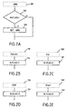
- FIGS. 2A to 2E show parts of flowcharts which determine the setting of the recording field.
- the list successively as a first recording a recording of the patient A with the organ 1 (for example, a lateral pulmonary uptake) requests and as a second recording another image of the patient A for a second organ, e.g. Lung p.a. (although in both cases the lungs are to be picked up, the p.a. and lateral uptake of this organ are treated like different organs with a different set of uptake parameters).
- the patient and admission list may prescribe a recording of the same organ (lung p.a.) in another patient B.
- the examiner stores the patient A on the patient table (or he positions it in front of the aforementioned wall stand) and adjusts the size of the recording field on the aperture unit with the setting member 54, whereby the flag is set. as shown in Fig. 2B.
- the examiner then goes into the room with the workstation and sets the X-ray device to the first recording, ie it is given for the recording of the patient A with the organ 1, whereby a setting value for the recording field is called.
- the flag is set, according to the procedure shown in Fig. 2A, the recording field is not set to this called set value.
- the examiner then triggers the first X-ray image, with the result that, according to FIG. 2D, the flag according to step 131 is reset.
- the patient support table can be designed in such a way that X-ray emitters 1 and image recorders 4 can be displaced relative to one another and in opposite directions at the same time, and tomograms can be created.
- X-ray emitters 1 and image recorders 4 can be displaced relative to one another and in opposite directions at the same time, and tomograms can be created.
- this layer-shot mode a series of layers at different depths is usually taken, and therefore in this mode a (slice) shot must not result in the above-described flag reset.
- the examiner specifies the second shot at the workstation, the set value for the second organ (lung pa) is called up as shown in FIG. 2A and adjusted via the aperture controller 53 and by the motor 52, so that the one from the previous shot Manual setting is overwritten.
- the examiner then places the patient A so that the second shot can be performed.
- the setting member 54 When he presses the setting member 54, the default setting of the aperture unit by the memory 61 for lung p.a. changed setting value accordingly, which has a renewed setting of the flag result.
- the flag is reset because of the paternity change (step 121), even if the same organ is to be recorded as in the previous recording.
- the manual settings made during the second recording are therefore overwritten according to the setting value specified for the organ to be recorded at the third (lung pa). This presetting can, if necessary, be changed by the examiner again with the setting member 54.
- the described procedure shows that the X-ray device offers the examiner maximum ergonomics with high flexibility of adjustment.
Landscapes
- Health & Medical Sciences (AREA)
- Life Sciences & Earth Sciences (AREA)
- Engineering & Computer Science (AREA)
- Medical Informatics (AREA)
- Physics & Mathematics (AREA)
- High Energy & Nuclear Physics (AREA)
- Radiology & Medical Imaging (AREA)
- Molecular Biology (AREA)
- Optics & Photonics (AREA)
- Pathology (AREA)
- Biophysics (AREA)
- Biomedical Technology (AREA)
- Heart & Thoracic Surgery (AREA)
- Nuclear Medicine, Radiotherapy & Molecular Imaging (AREA)
- Surgery (AREA)
- Animal Behavior & Ethology (AREA)
- General Health & Medical Sciences (AREA)
- Public Health (AREA)
- Veterinary Medicine (AREA)
- Spectroscopy & Molecular Physics (AREA)
- General Engineering & Computer Science (AREA)
- Apparatus For Radiation Diagnosis (AREA)
Description
Die Erfindung bezieht sich auf eine Röntgeneinrichtung mit einem Röntgenaufnahmegerät und einem Röntgengenerator zur Speisung eines mit dem Röntgenaufnahmegerät zusammenwirkenden Röntgenstrahlers und mit einer mit dem Röntgenstrahler verbundenen Blendeneinheit mit einstellbarer Blendenöffnung zwecks Vorgabe eines Aufnahmefeldes auf einem Röntgen-Bildaufnehmer, wobei die Blendenöffnung einerseits durch eine von einem Steuersystem gesteuerte Antriebseinheit und andererseits durch Einstellmittel zum manuellen Einstellen der Blendenöffnung einstellbar ist.The invention relates to an X-ray device with an X-ray recorder and an X-ray generator for supplying a cooperating with the X-ray radiograph X-ray and with an X-ray connected aperture unit with adjustable aperture for the purpose of specifying a recording field on an X-ray imager, wherein the aperture on the one hand by one of a Control system controlled drive unit and on the other hand adjustable by adjusting means for manually adjusting the aperture.
Röntgeneinrichtungen dieser Art zum Anfertigen von Bucky-Aufnahmen sind bekannt. Als Bildaufnehmer werden dabei Film-Folienkombinationen unterschiedlichen Formats verwendet, die sich in Kassetten mit daran angepaßten Abmessungen befinden. Der Untersucher wählt dabei das für die nachfolgende Röntgenaufnahme erforderliche Kassettenformat aus und legt die Kassette in die Röntgeneinrichtung ein. Diese besitzt eine Meßeinrichtung zur Erfassung des Kassettenformates. Das Steuersystem verstellt dann in Abhängigkeit von dem gemessenen Kassettenformat die Blendenöffnung so, daß das Aufnahmefeld dem Kassettenformat bzw. dem Format des darin befindlichen Films entspricht. Ein manuelles Einstellen des Aufnahmefeldes ist bei derartigen Röntgeneinrichtungen nur erforderlich, wenn der Untersucher das Aufnahmefeld einengen will.X-ray devices of this type for making Bucky pictures are known. Film-film combinations of different formats are used as imagers, which are located in cassettes with dimensions adapted thereto. The examiner selects the cassette format required for the subsequent x-ray exposure and places the cassette in the x-ray device. This has a measuring device for detecting the cassette format. The control system then adjusts the aperture as a function of the measured cassette size so that the recording field corresponds to the cassette format or the format of the film therein. Manual adjustment of the recording field is only necessary with such X-ray devices if the examiner wants to restrict the field of view.
Neuerdings werden als Bildaufnehmer sogenannte "digitale" Röntgendetektoren verwendet, die eine Vielzahl (z.B. 2000x2000) von matrixförmig angeordneten, für Licht oder Röntgenstrahlen empfindlichen Detektorelementen enthalten, die von der Röntgenstrahlenintensität abhängige elektrische Signale erzeugen, die in der Röntgeneinrichtung verarbeitet werden. Die Röntgeneinrichtung kann verschiedene Aufnahmeeinheiten umfassen, z.B. einen Rasteraufnahmetisch für Röntgenaufnahmen am liegenden Patienten und/oder ein Rasterwandstativ für Röntgenaufnahmen am stehenden Patienten; jede dieser Einheiten enthält nur einen einzigen solchen digitalen Detektor, dessen Abmessungen deshalb dem größtmöglichen Aufnahmeformat (z.B. 43x43 cm) entsprechen müssen. Eine automatische Einstellung der Blendenöffnung auf das Format dieses Bildaufnehmers würde aber in den meisten Fällen eine teilweise erhebliche manuelle Einengung des Aufnahmefeldes erfordern, was die Bedienung eines solchen Gerätes erschweren würde.Recently, so-called "digital" X-ray detectors are used as imagers, which contain a plurality (eg 2000x2000) of matrix-arranged, sensitive to light or X-ray detector elements that generate dependent on the X-ray intensity electrical signals that are processed in the X-ray device. The X-ray device may comprise various recording units, for example a raster-receiving table for X-ray exposures on the recumbent patient and / or a raster wall stand for X-ray exposures on the stationary patient; each of these units contains only one such digital detector, the dimensions of which are therefore the largest possible recording format (eg 43x43 cm) must correspond. An automatic adjustment of the aperture on the format of this image recorder would require in most cases, a partial considerable manual narrowing of the recording field, which would complicate the operation of such a device.
Aufgabe der vorliegenden Erfindung ist es, die Bedienung einer Röntgeneinrichtung zu vereinfachen, deren Aufnahemeeinheit(en) einen Bildaufnehmer mit jeweils nur einem einzigen (maximalen) Format hat(haben). Diese Aufgabe wird ausgehend von einer Röntgeneinrichtung der eingangs genannten Art dadurch gelöst, daß eine mit dem Steuersystem zusammenwirkende Speicheranordnung vorgesehen ist, in der für eine Anzahl von Organen je ein Satz von Aufnahmeparametern gespeichert ist, daß jeder Satz neben Aufnahmeparametern für den Röntgengenerator einen Einstellwert zur Einstellung des Aufnahmefeldes enthält, und daß bei einer Vorgabe eines Organs der Einstellwert aufgerufen und das Aufnahmefeld über das Steuersystem und die Antriebseinheit entsprechend dem zu dem vorgegebenen Organ gehörigen Einstellwert eingestellt wird.The object of the present invention is to simplify the operation of an X-ray device whose imaging unit (s) has (have) an image recorder with only one (maximum) format each. This object is achieved on the basis of an X-ray device of the type mentioned above in that a cooperating with the control system memory arrangement is provided, is stored for a number of organs per a set of recording parameters that each set in addition to recording parameters for the X-ray generator a setting for Setting the recording field contains, and that when a default of an organ of the set value is called and the recording field is set via the control system and the drive unit according to the set to the prescribed organ setting value.
Die Verwendung einer Speicheranordnung, in der für verschiedene Organe je ein Satz von Aufnahmeparametern gespeichert ist, ist in der Röntgentechnik seit langem bekannt. Bei diesen sogenannten APR (Anatomically Programmed Radiography)-Verfahren werden im wesentlichen Aufnahmeparameter für den Röntgengenerator, z.B. die Spannung an der Röntgenröhre, der Strom durch die Röntgenröhre und die Aufnahmedauer organabhängig gespeichert und bei einer Auswahl dieses Organs aufgerufen und eingestellt.The use of a memory arrangement in which a set of acquisition parameters is stored for different organs has long been known in x-ray technology. In these so-called APR (Anatomically Programmed Radiography) methods, substantially acquisition parameters for the X-ray generator, e.g. the voltage at the x-ray tube, the current through the x-ray tube and the recording time organ-dependent stored and called and selected in a selection of this organ.
Die Erfindung basiert auf der Erkenntnis, daß die Größe des Aufnahmefeldes mit dem Organ bzw. der Körperregion korreliert ist, die durch die nachfolgende Röntgenaufnahme abgebildet werden soll. Deshalb wird für jedes Organ zusätzlich die Größe des dafür erforderlichen Aufnahmefeldes gespeichert. Der gespeicherte Einstellwert wird bei einer Vorgabe dieses Organs aufgerufen und steuert über das Steuersystem und die Antriebseinheit die Blendeneinheit so, daß das vorgegebene Aufnahmefeld eingestellt wird. Der Untersucher muß danach das Aufnahmefeld - wenn überhaupt - nur geringfügig verändern.The invention is based on the recognition that the size of the recording field is correlated with the organ or body region which is to be imaged by the subsequent X-ray exposure. Therefore, the size of the required recording field is additionally stored for each organ. The stored set value is called upon a default of this organ and controls the aperture unit via the control system and the drive unit so that the predetermined recording field is set. The examiner then has to change the recording field only slightly, if at all.
Bei der manuellen Einstellung des Aufnahmefeldes befindet sich der Untersucher in der Nähe des - z.B. auf einem Patientenlagerungstisch gelagerten - Patienten. Die übrigen Einstellvorgänge hingegen, z.B. die Vorgabe eines Organs, die Auslösung einer Röntgenaufnahme usw. werden an einem Bedienpult bzw. einer Workstation vorgenommen, die sich in einem anderen Raum als der Patient befindet. Die Ausgestaltung nach Anspruch 2 verhindert dabei, daß die für die Aufnahme des betreffenden Organs manuell vorgegebene Einstellung durch einen für dieses Organ gespeicherten Einstellwert überschrieben und damit wieder rückgängig gemacht wird. Das entsprechend programmierte Steuersystem setzt sich dabei zweckmäßigerweise aus einem Blenden-Controller zusammen, der für die Steuerung der Antriebseinheit und der Blendeneinheit zuständig ist, sowie aus der Workstation, die alle Komponenten der Röntgeneinrichtung und den gesamten Aufnahmeablauf steuert.When setting the recording field manually, the examiner is in the vicinity of the - e.g. on a patient table - stored patients. The other adjustment operations, however, e.g. the specification of an organ, the triggering of an X-ray, etc. are performed on a control panel or a workstation, which is located in a different room than the patient. The embodiment according to
Die weitere Ausgestaltung nach Anspruch 3 ermöglicht allerdings dann einen Übergang von der manuellen Einstellung auf die gespeicherten Einstellwerte, wenn nach der manuellen Einstellung eine Röntgenaufnahme oder ein Patientenwechsel erfolgt ist.However, the further embodiment according to
Bucky-Aufnahmen oder Aufnahmen am Wandstativ werden im allgemeinen mit einem bestimmten Abstand zwischen Röntgenstrahler und Bildaufnehmer ausgeführt, z.B. 1,15 m. In diesem Fall entspricht jedes Aufnahmefeld einer bestimmten Blendenöffnung. Vielfach ist es aber erwünscht, den Abstand zwischen Röntgenstrahler und Bildaufnehmer zu vergrößern oder zu verkleinern, und die Weiterbildung nach Anspruch 4 bewirkt nun, daß bei einer Veränderung des genannten Abstandes auch die Blendenöffnung so verstellt wird, daß sich das gewünschte Aufnahmefeld in der Ebene des Bildaufnehmers ergibt.Bucky shots or wall mount shots are generally carried out with a certain distance between the X-ray source and imager, e.g. 1.15 m. In this case, each recording field corresponds to a specific aperture. In many cases, however, it is desirable to increase or decrease the distance between the X-ray source and the image recorder, and the further development according to
Anspruch 5 gibt an, bei welcher Art von Bildaufnehmern die Erfindung anwendbar ist. Grundsätzlich ist die Erfindung aber bei allen Aufnahmeeinheiten anwendbar, die lediglich über ein einziges Format des Bildaufnehmers verfügen.Claim 5 indicates in which type of imagers the invention is applicable. In principle, however, the invention is applicable to all recording units which have only a single format of the image recorder.
Die Erfindung wird nachstehend anhand der Zeichnungen näher erläutert. Es zeigen:
- Fig. 1
- eine erfindungsgemäße Röntgeneinrichtung und
- Fig. 2A-2E
- Ablaufdiagramme für die Steuerung der Blendeneinheit.
- Fig. 1
- an X-ray device according to the invention and
- Fig. 2A-2E
- Flowcharts for controlling the aperture unit.
Die in Fig. 1 dargestellte Röntgeneinrichtung umfaßt einen Röntgenstrahler 1, der von einem Röntgengenerator 2 gesteuert wird. Der Röntgenstrahler ist an einem nicht näher dargestellten Stativ befestigt und kann daran zumindest in vertikaler Richtung verschoben werden. Außerdem umfaßt die Röntgeneinrichtung einen Patientenlagerungstisch, der durch eine Tischplatte 3 symbolisch angedeutet ist, unterhalb der sich ein digitaler Bildaufnehmer 4 mit matrixförmigen Detektorelementen befindet. Zusätzlich zu dem Patientenlagerungstisch - oder auch an seiner statt - kann ein nicht näher dargestelltes Rasterwandstativ mit einem derartigen Bildaufnehmer vorgesehen sein.The X-ray device shown in Fig. 1 comprises an
Die Größe des Aufnahmefeldes, das auf dem Bildaufnehmer 4 von dem Röntgenstrahler 1 bestrahlt wird, wird durch eine Blendeneinheit 5 eingestellt. Die Blendenöffnung, d.h. der Öffnungswinkel des gestrichelt angedeuteten Strahlenbündels in der Zeichenebene, wird durch einen ersten Satz von Kollimatoren 51 beispielsweise aus Blei bestimmt, deren Kanten senkrecht zur Zeichenebene der Fig. 1 verlaufen. Außerdem ist ein zweiter Satz von Kollimatoren vorgesehen, in Fig. 1 aber nicht dargestellt, der zur Zeichenebene parallele Blendenkanten aufweist und den Öffnungswinkel des Strahlenbündels 10 senkrecht zur Zeichenebene bestimmt. Die Blendenöffnung kann durch einen Motor 52 verstellt werden, der sich - anders als in der Zeichnung dargestellt - in der Blendeneinheit 5 befindet. Der Motor 52 wird von einem Blenden-Controller 53 gesteuert, die mit einer Workstation 6 zusammenarbeitet.The size of the recording field which is irradiated on the
Außerdem kann die Blendenöffnung mit einem Einstellglied 54 manuell vom Untersucher eingestellt werden. Die Betätigung des Einstellgliedes 54 wird vom Blenden-Controller 53 registriert. Die Größe des eingestellten Aufnahmefeldes kann vor einer Aufnahme vom Untersucher mit Hilfe eines in der Blendeneinheit 5 untergebrachten, nicht näher dargestellten Lichtvisiers überprüft werden, das ein Lichtbündel erzeugt, das durch die Kollimatoren 51 usw. in gleicher Weise begrenzt wird wie bei der Aufnahme das Röntgenstrahlenbündel 10. Der Abstand zwischen dem Röntgenstrahler und dem Bildaufnehmer wird von einer Meßeinrichtung 55 gemessen, und der Meßwert wird dem Blenden-Controller 53 übermittelt.In addition, the aperture can be adjusted with an
Die Workstation 6 steuert u.a. den Blenden-Controller 53 und den Röntgengenerator 2. Sie kann dabei auf eine Speicheranordnung 61 zugreifen, in der in Form einer Datenbank für eine Vielzahl von Organen je ein Datensatz gespeichert ist. Jeder Datensatz enthält die für das jeweilige Organ im Normalfall optimalen Aufnahmepararneter, darunter auch einen Wert für die Größe des einzustellenden Aufnahmefeldes. Dieser Einstellwert kann dem Blenden-Controller 53 zwecks Einstellung des Aufnahmefeldes unter Berücksichtigung des gemessenen Abstandes zwischen Röntgenstrahler und Bildaufnehmer vorgegeben werden.The
Die Workstation kann darüber hinaus aus den Signalen des Röntgenbildaufnehmers 4 eine Röntgenaufnahme rekonstruieren und diese auf einem Monitor 62 wiedergeben. Andererseits kann die Workstation auf dem Monitor eine Patienten- und Aufnahmeliste vorgeben, die neben dem Namen eines Patienten die Organe bzw. Körperregionen enthält, die für diesen Patienten durch eine Röntgenaufnahme dargestellt werden soll. Diese Liste kann der Workstation 6 beispielsweise über eine sogenannte RIS-Verbindung (Radiology Information System) vorgegeben werden. Außerdem ist eine Eingabeeinheit 63 vorgesehen, z.B. eine Tastatur- und/oder eine Touchscreen-Einheit,um mit der Workstation 6 zu kommunizieren. Der Patientenlagerungstisch 3 (ggf. auch das oben erwähnte Rasterwandstativ) mit dem Röntgenstrahler 1 und der Blendeneinheit 5 befinden sich in einem anderen Raum als die Komponenten 6, 61, 62 und 63. Bei jeder Röntgenaufnahme ist der Untersucher in beiden Räumen tätig: bei der Einstellung der Aufnahmeparameter durch Vorgabe des Organs sowie bei der Auslösung einer Röntgenaufnahme in dem einen Raum und bei der Positionierung des Patienten und ggf. der manuellen Einstellung der Blendeneinheit in dem anderen Raum.The workstation can also reconstruct an X-ray image from the signals of the
In den Fig. 2A bis 2E sind Teile von Ablaufdiagrammen dargestellt, die die Einstellung des Aufnahmefeldes bestimmen. Gemäß Fig. 2A erfolgt nach der Vorgabe eines Organs bzw. dem Aufruf von APR-Daten im Schritt 101 eine Abfrage, ob ein bestimmtes Flag gesetzt ist (M-FLAG= 1) oder nicht (Schritt 102). Wenn das Flag nicht gesetzt ist, erzeugt die Workstation im Schritt 103 den Befehl für den Blenden-Controller 53, die Größe des Aufnahmefeldes unter Berücksichtigung des Abstandes zwischen Röntgenstrahler 1 und Bildaufnehmer 4 entsprechend dem für das aufzunehmende Organ gespeicherten Einstellwert einzustellen. Ist hingegen das Flag gesetzt, bleibt die Einstellung unverändert. Wie in den Fig. 2B.....2E dargestellt, kann das Flag in Abhängigkeit von vier verschiedenen Ereignissen gesetzt bzw. zurückgesetzt werden:FIGS. 2A to 2E show parts of flowcharts which determine the setting of the recording field. According to FIG. 2A, after the specification of an organ or the call of APR data in
Gemäß Fig. 2B wird im Falle einer manuellen Einstellung der Blendenöffnung mittels des Einstellgliedes 54 (Block 110) das Flag im Schritt 111 gesetzt (M-Flag=1). Wenn hingegen ein Patientenwechsel erfolgt (Block 120), wird im Schritt 121 das Flag zurückgesetzt (M-FLAG=0 - Fig. 2C). Das gleiche passiert im Schritt 131 gemäß Fig. 2D nach Auslösung einer Röntgenaufnahme (Block 130) oder im Schritt 141 bei einem (Neu-) Start des Systems 140.Referring to Fig. 2B, in the case of manual setting of the aperture by means of the adjusting member 54 (block 110), the flag is set in step 111 (M flag = 1). If, on the other hand, a patient change occurs (block 120), the flag is reset in step 121 (M-FLAG = 0 - Fig. 2C). The same thing happens in
Im folgenden wird erläutert, wie die Röntgeneinheit arbeitet, wenn der Untersucher eine auf dem Monitor 62 vorgegebene Patienten- und Aufnahmeliste abarbeitet. Dabei sei angenommen, daß die Liste nacheinander als erste Aufnahme eine Aufnahme des Patienten A mit dem Organ 1 (z.B. eine laterale Lungenaufnahme) anfordert und als zweite Aufnahme eine weitere Aufnahme des Patienten A für ein zweites Organ, z.B. Lunge p.a. (obwohl in beiden Fällen die Lunge aufgenommen werden soll, werden die p.a. und die laterale Aufnahme dieses Organs wie verschiedene Organe mit einem unterschiedlichen Satz von Aufnahmeparametern behandelt). Als dritte Aufnahme möge die Patienten- und Aufnahmeliste eine Aufnahme des gleichen Organs (Lunge p.a.) bei einem anderen Patienten B vorschreiben.The following explains how the X-ray unit works when the examiner processes a patient and admission list specified on the
Bei der ersten Aufnahme lagert der Untersucher den Patienten A auf dem Patientenlagerungstisch (oder er positioniert ihn vor dem erwähnten Wandstativ) und stellt an der Blendeneinheit mit dem Einstellglied 54 die Größe des Aufnahmefeldes ein, wodurch das Flag gesetzt wird,. wie in Fig. 2B dargestellt. Der Untersucher geht dann in den Raum mit der Workstation und stellt die Röntgeneinrichtung auf die erste Aufnahme ein, d.h. es wird für die Aufnahme der Patient A mit dem Organ 1 vorgegeben, wodurch ein Einstellwert für das Aufnahmefeld aufgerufen wird. Da das Flag jedoch gesetzt ist, wird gemäß dem in Fig. 2A dargestellten Ablauf das Aufnahmefeld nicht auf diesen aufgerufenen Einstellwert eingestellt. Der Untersucher löst dann die erste Röntgenaufnahme aus, was zur Folge hat, daß gemäß Fig. 2D das Flag gemäß dem Schritt 131 zurückgesetzt wird.At the first shot, the examiner stores the patient A on the patient table (or he positions it in front of the aforementioned wall stand) and adjusts the size of the recording field on the aperture unit with the setting
Der Patientenlagerungstisch kann ggf so ausgebildet sein, daß Röntgenstrahler 1 und Bildaufnehmer 4 gleichzeitig und gegensinnig zueinander verschoben und Schichtaufnahmen erstellt werden können. In diesem Schichtaufnahme-Modus wird meist eine Serie von Schichten in unterschiedlicher Tiefe aufgenommen, und deshalb darf in diesem Modus eine (Schicht-)Aufnahme nicht zu der oben beschriebenen Zurücksetzung des Flags führen.If necessary, the patient support table can be designed in such a way that
Wenn der Untersucher daher an der Workstation die zweite Aufnahme vorgibt, wird gemäß Fig. 2A der Einstellwert für das zweite Organ (Lunge pa) aufgerufen und über den Blenden-Controller 53 und durch den Motor 52 eingestellt, so daß die von der vorigen Aufnahme vorhandene manuelle Einstellung überschrieben wird. Der Untersucher lagert dann den Patienten A so, daß die zweite Aufnahme ausgeführt werden kann. Wenn er dabei das Einstellglied 54 betätigt, wird die Voreinstellung der Blendeneinheit durch den aus dem Speicher 61 für Lunge p.a. aufgerufenen Einstellwert entsprechend geändert, was ein erneutes Setzen des Flags zur Folge hat.Therefore, if the examiner specifies the second shot at the workstation, the set value for the second organ (lung pa) is called up as shown in FIG. 2A and adjusted via the
Wenn nach dieser zweiten Aufnahme an der Workstation 3 die dritte Aufnahme (Patient B) in der Liste vorgegeben wird, wird das Flag wegen des Patirentenwechssels zurückgesetzt (Schritt 121), selbst wenn dasselbe Organ aufzunehmen ist wie bei der vorangegangenen Aufnahme. Die bei der zweiten Aufnahme vorgenommenen manuellen Einstellungen werden deshalb entsprechend dem für das bei der dritte aufzunehmende Organ (Lunge pa) vorgegebenen Einstellwert überschrieben. Diese Voreinstellung kann der Untersucher - falls erforderlich - wiederum mit dem Einstellglied 54 verändern.If after this second recording on the
Der beschriebene Ablauf zeigt, daß die Röntgeneinrichtung dem Untersucher ein Höchstmaß an Ergonomie bei gleichzeitig hoher Flexibilität der Einstellung bietet.The described procedure shows that the X-ray device offers the examiner maximum ergonomics with high flexibility of adjustment.
Claims (5)
- An X-ray device which includes an X-ray imaging apparatus (3) and an X-ray generator (2) for powering an X-ray source (1) which co-operates with the X-ray imaging apparatus and also includes a diaphragm unit (5) which is connected to the X-ray source (1) and includes an adjustable diaphragm aperture in order to preset an exposure field on an X-ray image detection device (4), the diaphragm aperture being adjustable on the one hand by a drive unit (52) which is controlled by a control system (6, 53) and, on the other hand, by adjusting means (54) for manual adjustment of the diaphragm aperture, characterized in that a storage device (61) co-operating with the control system (6, 53) is provided in which device a respective set of exposure parameters is stored for each of a number of organs, that each set includes, in addition to the exposure parameters for the X-ray generator; an adjustment value for adjusting the exposure field, and that, when an organ is selected, the adjustment value is fetched and the exposure field is adjusted, by way of the control system and the drive unit, in conformity with the adjustment value associated with the selected organ.
- An X-ray device as claimed in claim 1, characterized in that the control system (6, 53) is programmed in such a manner that, after actuation of the adjustment means (54), the manual adjustment of the exposure field is carried out or preserved independently of an adjustment value fetched before or after that.
- An X-ray device as claimed in claim 2, characterized in that the control system (6, 53) is programmed in such a manner that an exposure field adjusted by actuation of the adjusting means (54) is adjusted in conformity with the respectgive adjustment value fetched subsequent to an X-ray exposure or a change of patient to be examined.
- An X-ray device as claimed in claim 1, characterized in that the distance between the X-ray source (1) and the X-ray image detection device (4) is adjustable, that means (55) are provided for measuring this distance, and that the control system (6, 53) is programmed in such a manner that in dependence on the measured distance the diaphragm aperture has a value such that the size of the exposure field on the image detection device (4) assumes its preset value.
- An X-ray device as claimed in claim 1, characterized in that use is made of an X-ray image detection device (4) in the form of a flat detector with light-sensitive or X-ray-sensitive detector elements which are arranged in the form of a matrix.
Applications Claiming Priority (2)
| Application Number | Priority Date | Filing Date | Title |
|---|---|---|---|
| DE19845650 | 1998-10-05 | ||
| DE19845650 | 1998-10-05 |
Publications (2)
| Publication Number | Publication Date |
|---|---|
| EP0993239A1 EP0993239A1 (en) | 2000-04-12 |
| EP0993239B1 true EP0993239B1 (en) | 2005-09-21 |
Family
ID=7883335
Family Applications (1)
| Application Number | Title | Priority Date | Filing Date |
|---|---|---|---|
| EP99203176A Expired - Lifetime EP0993239B1 (en) | 1998-10-05 | 1999-09-29 | X-ray apparatus |
Country Status (4)
| Country | Link |
|---|---|
| US (1) | US6259767B1 (en) |
| EP (1) | EP0993239B1 (en) |
| JP (1) | JP2000107175A (en) |
| DE (1) | DE59912574D1 (en) |
Families Citing this family (22)
| Publication number | Priority date | Publication date | Assignee | Title |
|---|---|---|---|---|
| DE10019242B4 (en) * | 2000-04-18 | 2007-08-23 | Siemens Ag | Method for controlling an X-ray diagnostic device with solid-state image converter for mammography |
| US6502985B1 (en) * | 2000-05-05 | 2003-01-07 | Canon Kabushiki Kaisha | Auto-collimating digital X-ray system |
| JP3848082B2 (en) * | 2000-12-27 | 2006-11-22 | キヤノン株式会社 | X-ray imaging apparatus and method, control apparatus and method |
| US6795528B2 (en) * | 2001-01-12 | 2004-09-21 | Canon Kabushiki Kaisha | Radiographic apparatus, radiographic method, and computer-readable storage medium |
| DE10117017C2 (en) * | 2001-04-05 | 2003-06-05 | Siemens Ag | Electrically insulating polymer foam with high thermal conductivity, process for its production and use of the same |
| US6781060B2 (en) | 2002-07-26 | 2004-08-24 | X-Ray Optical Systems Incorporated | Electrical connector, a cable sleeve, and a method for fabricating an electrical connection |
| DE10161708A1 (en) * | 2001-12-15 | 2003-06-18 | Philips Intellectual Property | Medical X-ray imaging device, especially for use with anatomically programmed radiography (APR) technology, has a storage arrangement that allows automatic updating of operating parameters |
| US20040066885A1 (en) * | 2002-07-08 | 2004-04-08 | Kabushiki Kaisha Toshiba | X-ray diagnosis apparatus |
| DE10311627B4 (en) * | 2003-03-14 | 2007-07-19 | Siemens Ag | Method and device for determining and documenting applied X-ray exposure values |
| US7835496B2 (en) * | 2008-04-22 | 2010-11-16 | Siemens Aktiengesellschaft | User interface of an X-ray system and method for manufacturing such an user interface |
| JP2010057633A (en) * | 2008-09-02 | 2010-03-18 | Fujifilm Corp | Radiographic apparatus and radiographic method |
| CN102440079B (en) * | 2009-04-07 | 2014-12-24 | 株式会社岛津制作所 | X-ray imaging device |
| DE102010013591A1 (en) * | 2010-03-31 | 2011-10-06 | DüRR DENTAL AG | X-ray apparatus and method for producing X-ray images for dental or orthodontic diagnostics |
| JP5848573B2 (en) * | 2011-10-04 | 2016-01-27 | 株式会社日立製作所 | Moving body tracking radiotherapy system |
| JP6021403B2 (en) * | 2012-04-19 | 2016-11-09 | キヤノン株式会社 | Radiation imaging device |
| KR101253114B1 (en) * | 2012-11-21 | 2013-04-10 | 건국대학교 산학협력단 | Apparatus for measureing bone mineral density using x-ray |
| DE102013219249A1 (en) * | 2013-09-25 | 2015-03-26 | Siemens Aktiengesellschaft | Method and system for automatic selection of a scan protocol |
| US9566040B2 (en) * | 2014-05-14 | 2017-02-14 | Swissray Asia Healthcare Co., Ltd. | Automatic collimator adjustment device with depth camera and method for medical treatment equipment |
| JP6122410B2 (en) * | 2014-09-22 | 2017-04-26 | 富士フイルム株式会社 | Portable console, portable console control method, portable console program, and radiation imaging system |
| JP2016059739A (en) * | 2014-09-22 | 2016-04-25 | 富士フイルム株式会社 | Portable console, control method for portable console, program for portable console, and radiographic system |
| RU2701123C2 (en) * | 2014-10-13 | 2019-09-24 | Конинклейке Филипс Н.В. | Detector rotation, controlled by x-ray radiation collimation |
| CN110090031A (en) * | 2018-01-30 | 2019-08-06 | 上海西门子医疗器械有限公司 | Automatic exposure dosage adjusting method, storage medium and X-ray machine for X-ray machine |
Family Cites Families (14)
| Publication number | Priority date | Publication date | Assignee | Title |
|---|---|---|---|---|
| DE2424634B2 (en) * | 1974-05-21 | 1978-06-01 | Siemens Ag, 1000 Berlin Und 8000 Muenchen | X-ray diagnostic system |
| JPS584534A (en) * | 1981-06-30 | 1983-01-11 | 株式会社東芝 | Radioactive ray diagnostic apparatus |
| US4403337A (en) * | 1981-11-16 | 1983-09-06 | Bennett X-Ray Corp. | Automated setting of technic factors for x-ray examinations |
| US4597094A (en) * | 1983-12-01 | 1986-06-24 | Bennett X-Ray Corp. | Automated setting of technic factors for x-ray examinations with a ranging transducer moving in and out of the x-ray beam path |
| JPH0546000Y2 (en) * | 1985-11-01 | 1993-11-30 | ||
| JPS6428613U (en) * | 1987-08-13 | 1989-02-20 | ||
| DE3732634A1 (en) * | 1987-09-28 | 1989-04-06 | Siemens Ag | X-RAY DIAGNOSTIC DEVICE |
| JPH0719453Y2 (en) * | 1989-12-22 | 1995-05-10 | 株式会社島津製作所 | X-ray movable diaphragm control device |
| JPH06209925A (en) * | 1992-07-28 | 1994-08-02 | Toshiba Corp | X-ray radioscopy photographing device |
| US5588036A (en) * | 1993-06-28 | 1996-12-24 | Kabushiki Kaisha Toshiba | X-ray CT apparatus and radiographing method using same |
| JP3538286B2 (en) * | 1996-10-08 | 2004-06-14 | 株式会社日立メディコ | X-ray equipment |
| JPH10200816A (en) * | 1997-01-13 | 1998-07-31 | Shimadzu Corp | X-ray photographing device |
| JP3554129B2 (en) * | 1997-01-17 | 2004-08-18 | キヤノン株式会社 | Radiography equipment |
| JPH10234714A (en) * | 1997-02-21 | 1998-09-08 | Toshiba Iyou Syst Eng Kk | X-ray radiographic device |
-
1999
- 1999-09-29 EP EP99203176A patent/EP0993239B1/en not_active Expired - Lifetime
- 1999-09-29 DE DE59912574T patent/DE59912574D1/en not_active Expired - Lifetime
- 1999-10-04 US US09/411,757 patent/US6259767B1/en not_active Expired - Lifetime
- 1999-10-04 JP JP11283425A patent/JP2000107175A/en active Pending
Also Published As
| Publication number | Publication date |
|---|---|
| DE59912574D1 (en) | 2006-02-02 |
| JP2000107175A (en) | 2000-04-18 |
| US6259767B1 (en) | 2001-07-10 |
| EP0993239A1 (en) | 2000-04-12 |
Similar Documents
| Publication | Publication Date | Title |
|---|---|---|
| EP0993239B1 (en) | X-ray apparatus | |
| DE4210120C1 (en) | X=ray appts. for peripheral angiography - calculates relative positioning of appts. and patient support using data derived from patient | |
| EP0632995B1 (en) | Dental X-ray diagnostic device | |
| EP0856282B1 (en) | Radiographic apparatus | |
| EP0139941B1 (en) | X-ray diagnosis device having a patient's couch and a primary radiation diaphragm | |
| DE69304367T2 (en) | X-ray machine for medical use | |
| EP0858773B1 (en) | Device for producing X-rays of parts of a human body | |
| DE69331623T2 (en) | Automatic route search of digital X-ray images to the selected destination | |
| DE10354899B4 (en) | X-ray device and method for producing an X-ray image data set | |
| DE19754670A1 (en) | X-ray machine | |
| DE2815252A1 (en) | VARIABLE COLLIMATOR | |
| DE10314536A1 (en) | Method of generating an X-ray | |
| DE69120338T2 (en) | Device for medical imaging with precise positioning of the patient | |
| DE102006029327A1 (en) | Compensating method, for offset signal generated by flat panel detector in radiographic device, involves applying selected offset map to subsequent X-ray images from radiographic device | |
| DE60025469T2 (en) | IMAGING DEVICE | |
| DE2117908A1 (en) | Tomographic imaging device | |
| DE19748670A1 (en) | Modulating data acquisition system gain with computer tomography system | |
| DE3037478A1 (en) | DEVICE FOR THE SIMULTANEOUS PRODUCTION OF A VARIETY OF PANORAMIC LAYER PICTURES OF THE FOCAL CURVE OF THE DENTAL ARCH | |
| DE10234465A1 (en) | X-ray sectional-imaging method in which the height of a sectional image is set using a camera arrangement for imaging the patient from the side so that a reference marking can be made on a reference image | |
| EP1321099B1 (en) | X-ray apparatus with memory means to store take parameters of the radiographs | |
| DE102004052911B4 (en) | X-ray source with a radiator housing, X-ray device with such an X-ray source and computer tomography device with such X-ray device | |
| DE2548531C2 (en) | ||
| EP2926734B1 (en) | Method for setting up a patient irradiation device | |
| DE102006048233A1 (en) | X-ray arrangement for patient examination, has computing unit with converter having input device for complete data set of simply adjustable system parameters that are fed by user for convert into complete data set of image chain parameters | |
| EP0216995B1 (en) | Diagnostic x-ray arrangement |
Legal Events
| Date | Code | Title | Description |
|---|---|---|---|
| PUAI | Public reference made under article 153(3) epc to a published international application that has entered the european phase |
Free format text: ORIGINAL CODE: 0009012 |
|
| AK | Designated contracting states |
Kind code of ref document: A1 Designated state(s): DE FR GB NL |
|
| AX | Request for extension of the european patent |
Free format text: AL;LT;LV;MK;RO;SI |
|
| 17P | Request for examination filed |
Effective date: 20001012 |
|
| AKX | Designation fees paid |
Free format text: DE FR GB NL |
|
| RAP1 | Party data changed (applicant data changed or rights of an application transferred) |
Owner name: KONINKLIJKE PHILIPS ELECTRONICS N.V. Owner name: PHILIPS CORPORATE INTELLECTUAL PROPERTY GMBH |
|
| RAP1 | Party data changed (applicant data changed or rights of an application transferred) |
Owner name: KONINKLIJKE PHILIPS ELECTRONICS N.V. Owner name: PHILIPS INTELLECTUAL PROPERTY & STANDARDS GMBH |
|
| GRAP | Despatch of communication of intention to grant a patent |
Free format text: ORIGINAL CODE: EPIDOSNIGR1 |
|
| GRAS | Grant fee paid |
Free format text: ORIGINAL CODE: EPIDOSNIGR3 |
|
| GRAA | (expected) grant |
Free format text: ORIGINAL CODE: 0009210 |
|
| AK | Designated contracting states |
Kind code of ref document: B1 Designated state(s): DE FR GB NL |
|
| PG25 | Lapsed in a contracting state [announced via postgrant information from national office to epo] |
Ref country code: NL Free format text: LAPSE BECAUSE OF FAILURE TO SUBMIT A TRANSLATION OF THE DESCRIPTION OR TO PAY THE FEE WITHIN THE PRESCRIBED TIME-LIMIT Effective date: 20050921 |
|
| REG | Reference to a national code |
Ref country code: GB Ref legal event code: FG4D Free format text: NOT ENGLISH |
|
| REF | Corresponds to: |
Ref document number: 59912574 Country of ref document: DE Date of ref document: 20051027 Kind code of ref document: P |
|
| GBT | Gb: translation of ep patent filed (gb section 77(6)(a)/1977) |
Effective date: 20051125 |
|
| REG | Reference to a national code |
Ref country code: GB Ref legal event code: 746 Effective date: 20051205 |
|
| REF | Corresponds to: |
Ref document number: 59912574 Country of ref document: DE Date of ref document: 20060202 Kind code of ref document: P |
|
| NLV1 | Nl: lapsed or annulled due to failure to fulfill the requirements of art. 29p and 29m of the patents act | ||
| PLBE | No opposition filed within time limit |
Free format text: ORIGINAL CODE: 0009261 |
|
| STAA | Information on the status of an ep patent application or granted ep patent |
Free format text: STATUS: NO OPPOSITION FILED WITHIN TIME LIMIT |
|
| 26N | No opposition filed |
Effective date: 20060622 |
|
| PG25 | Lapsed in a contracting state [announced via postgrant information from national office to epo] |
Ref country code: FR Free format text: LAPSE BECAUSE OF FAILURE TO SUBMIT A TRANSLATION OF THE DESCRIPTION OR TO PAY THE FEE WITHIN THE PRESCRIBED TIME-LIMIT Effective date: 20061020 |
|
| EN | Fr: translation not filed | ||
| PG25 | Lapsed in a contracting state [announced via postgrant information from national office to epo] |
Ref country code: FR Free format text: LAPSE BECAUSE OF FAILURE TO SUBMIT A TRANSLATION OF THE DESCRIPTION OR TO PAY THE FEE WITHIN THE PRESCRIBED TIME-LIMIT Effective date: 20050930 |
|
| PG25 | Lapsed in a contracting state [announced via postgrant information from national office to epo] |
Ref country code: FR Free format text: LAPSE BECAUSE OF FAILURE TO SUBMIT A TRANSLATION OF THE DESCRIPTION OR TO PAY THE FEE WITHIN THE PRESCRIBED TIME-LIMIT Effective date: 20050921 |
|
| REG | Reference to a national code |
Ref country code: DE Ref legal event code: R081 Ref document number: 59912574 Country of ref document: DE Owner name: PHILIPS GMBH, DE Free format text: FORMER OWNER: PHILIPS INTELLECTUAL PROPERTY & STANDARDS GMBH, 20099 HAMBURG, DE Effective date: 20140327 Ref country code: DE Ref legal event code: R081 Ref document number: 59912574 Country of ref document: DE Owner name: PHILIPS DEUTSCHLAND GMBH, DE Free format text: FORMER OWNER: PHILIPS INTELLECTUAL PROPERTY & STANDARDS GMBH, 20099 HAMBURG, DE Effective date: 20140327 |
|
| REG | Reference to a national code |
Ref country code: DE Ref legal event code: R082 Ref document number: 59912574 Country of ref document: DE Representative=s name: MEISSNER BOLTE PATENTANWAELTE RECHTSANWAELTE P, DE Ref country code: DE Ref legal event code: R082 Ref document number: 59912574 Country of ref document: DE Representative=s name: MEISSNER, BOLTE & PARTNER GBR, DE Ref country code: DE Ref legal event code: R081 Ref document number: 59912574 Country of ref document: DE Owner name: PHILIPS GMBH, DE Free format text: FORMER OWNER: PHILIPS DEUTSCHLAND GMBH, 20099 HAMBURG, DE |
|
| PGFP | Annual fee paid to national office [announced via postgrant information from national office to epo] |
Ref country code: GB Payment date: 20180928 Year of fee payment: 20 |
|
| PGFP | Annual fee paid to national office [announced via postgrant information from national office to epo] |
Ref country code: DE Payment date: 20181130 Year of fee payment: 20 |
|
| REG | Reference to a national code |
Ref country code: DE Ref legal event code: R071 Ref document number: 59912574 Country of ref document: DE |
|
| REG | Reference to a national code |
Ref country code: GB Ref legal event code: PE20 Expiry date: 20190928 |
|
| PG25 | Lapsed in a contracting state [announced via postgrant information from national office to epo] |
Ref country code: GB Free format text: LAPSE BECAUSE OF EXPIRATION OF PROTECTION Effective date: 20190928 |