EP0992813A2 - Radio wave arrival direction estimating antenna apparatus - Google Patents
Radio wave arrival direction estimating antenna apparatus Download PDFInfo
- Publication number
- EP0992813A2 EP0992813A2 EP99119850A EP99119850A EP0992813A2 EP 0992813 A2 EP0992813 A2 EP 0992813A2 EP 99119850 A EP99119850 A EP 99119850A EP 99119850 A EP99119850 A EP 99119850A EP 0992813 A2 EP0992813 A2 EP 0992813A2
- Authority
- EP
- European Patent Office
- Prior art keywords
- antenna
- frequency
- arrival direction
- section
- signal
- Prior art date
- Legal status (The legal status is an assumption and is not a legal conclusion. Google has not performed a legal analysis and makes no representation as to the accuracy of the status listed.)
- Granted
Links
- 238000006243 chemical reaction Methods 0.000 claims abstract description 56
- 230000005855 radiation Effects 0.000 claims abstract description 29
- 230000005540 biological transmission Effects 0.000 claims description 52
- 238000012937 correction Methods 0.000 claims description 10
- 238000005070 sampling Methods 0.000 claims description 6
- 238000012360 testing method Methods 0.000 claims description 3
- 238000012545 processing Methods 0.000 abstract description 24
- 238000010586 diagram Methods 0.000 description 19
- 238000000034 method Methods 0.000 description 18
- 238000005516 engineering process Methods 0.000 description 6
- 238000004364 calculation method Methods 0.000 description 5
- 230000015572 biosynthetic process Effects 0.000 description 4
- 238000004891 communication Methods 0.000 description 3
- 239000011159 matrix material Substances 0.000 description 2
- 238000010295 mobile communication Methods 0.000 description 2
- 238000001228 spectrum Methods 0.000 description 2
- 230000002194 synthesizing effect Effects 0.000 description 2
- 239000013598 vector Substances 0.000 description 2
- 230000003044 adaptive effect Effects 0.000 description 1
- 238000007796 conventional method Methods 0.000 description 1
- 238000013480 data collection Methods 0.000 description 1
- 230000003111 delayed effect Effects 0.000 description 1
- 238000013461 design Methods 0.000 description 1
- 230000002542 deteriorative effect Effects 0.000 description 1
- 230000008030 elimination Effects 0.000 description 1
- 238000003379 elimination reaction Methods 0.000 description 1
- 238000011156 evaluation Methods 0.000 description 1
- 238000004519 manufacturing process Methods 0.000 description 1
- 238000012986 modification Methods 0.000 description 1
- 230000004048 modification Effects 0.000 description 1
Images


Classifications
-
- G—PHYSICS
- G01—MEASURING; TESTING
- G01S—RADIO DIRECTION-FINDING; RADIO NAVIGATION; DETERMINING DISTANCE OR VELOCITY BY USE OF RADIO WAVES; LOCATING OR PRESENCE-DETECTING BY USE OF THE REFLECTION OR RERADIATION OF RADIO WAVES; ANALOGOUS ARRANGEMENTS USING OTHER WAVES
- G01S3/00—Direction-finders for determining the direction from which infrasonic, sonic, ultrasonic, or electromagnetic waves, or particle emission, not having a directional significance, are being received
- G01S3/02—Direction-finders for determining the direction from which infrasonic, sonic, ultrasonic, or electromagnetic waves, or particle emission, not having a directional significance, are being received using radio waves
- G01S3/74—Multi-channel systems specially adapted for direction-finding, i.e. having a single antenna system capable of giving simultaneous indications of the directions of different signals
-
- G—PHYSICS
- G01—MEASURING; TESTING
- G01S—RADIO DIRECTION-FINDING; RADIO NAVIGATION; DETERMINING DISTANCE OR VELOCITY BY USE OF RADIO WAVES; LOCATING OR PRESENCE-DETECTING BY USE OF THE REFLECTION OR RERADIATION OF RADIO WAVES; ANALOGOUS ARRANGEMENTS USING OTHER WAVES
- G01S3/00—Direction-finders for determining the direction from which infrasonic, sonic, ultrasonic, or electromagnetic waves, or particle emission, not having a directional significance, are being received
- G01S3/02—Direction-finders for determining the direction from which infrasonic, sonic, ultrasonic, or electromagnetic waves, or particle emission, not having a directional significance, are being received using radio waves
- G01S3/14—Systems for determining direction or deviation from predetermined direction
Definitions
- the present invention relates to a radio wave arrival direction estimating antenna apparatus for controlling a radiation pattern of an antenna used in a base station in a mobile communication system, mainly such as a portable telephone, a PHS and a pager.
- TDMA Time Division Multiple Access
- FDMA Frequency Division Multiple Access
- CDMA Code Division Multiple Access
- a base station has a service area which is fixed with a predetermined size, and communicates mobile stations only existing in such an area.
- the frequency used by the base station and the mobile stations existing in the service area of the base station is also predetermined in such a manner that the interference does not occur in neighboring base stations and mutual mobile stations. Therefore, the number of mobile stations to be accommodated in an area of a base station is limited in the above-mentioned systems.
- such a number is limited by the total number of communication slots assigned for mobile stations.
- such a number is limited by the total number of frequency channels.
- such a number is limited by an interference elimination capability determined by a ratio of a data transmission rate and a spread spectrum chip rate.
- this technology it is possible to reduce interference in other mobile stations and base stations and to increase a communicable distance, by setting a beam of the radiation pattern to be narrow.
- such a technique is achieved with a configuration composed of a radio wave arrival direction estimating section, a digital beam generating section and others, using a MUSIC method and an ESPRIT method as a radio wave arrival direction estimating technique, as described, for example, "Trial Manufacture and Evaluation of Broadband Adaptive Array Antenna" (Technical report of IEICE, AP97-76, 1997-07, Pages 39 to 44).
- An object of the present invention is to achieve a radio wave arrival direction estimating antenna apparatus for enabling the processing in a practical time for arrival direction estimation and antenna radiation pattern control with respect to a mobile station which moves around a base station with a high speed.
- a radio wave arrival direction estimating antenna apparatus having an array antenna with a plurality of antenna elements each for receiving a radio wave transmitted from a mobile station in a base station, a frequency converting section for frequency-converting a received RF frequency signal at each antenna element of the array antenna into a respective intermediate frequency signal, an analog-digital conversion section for converting the intermediate frequency signal into digital data, a downsampling section for sampling the digital data obtained in the analog-digital conversion section at a lower frequency, an arrival direction estimating section for estimating an arrival direction of the radio wave using digital data converted in the analog-digital conversion section, and an arrival direction tracking section for estimating a change of the arrival direction of the radio wave from the mobile station, using an estimated result by the arrival direction estimating section as an initial value and digital data sampled at a lower frequency by the downsampling section, to determine a direction sequentially.
- the arrival direction estimating section estimates the number of mobile stations existing around the base station and positions thereof at certain intervals using the MUSIC method or the ESPRIT method. Using the estimated value as initial values, the arrival direction tracking section calculates a difference between a present direction where a mobile station exits and a previous direction obtained one sample before the present time, and estimates a direction of the mobile station using digital data. It is thereby possible to simplify the processing for estimating a direction of a mobile station, and to correctly estimate the number of mobile stations and directions thereof because the arrival direction estimating section estimates the number of mobile stations and directions thereof at certain intervals, thus enabling the judgment of a change of the number of mobile stations. Further, the arrival direction estimating section estimates an arrival direction of radio wave at a short internal, so that the arrival direction tracking section can track a moving of a mobile station adequately.
- FIG.1 is a block diagram illustrating a configuration of a radio wave arrival direction estimating antenna apparatus according to the first embodiment of the present invention.
- reference number 11 denotes an array antenna, which is provided in a base station and has a plurality of antenna elements for receiving radio waves transmitted from mobile stations.
- Reference number 12 denotes a frequency conversion section which frequency-converts a received RF frequency signal received at each antenna element of array antenna 11 into a respective intermediate frequency signal.
- Reference number 13 denotes an analog-digital conversion section which converts the intermediate frequency signal into digital data.
- Reference number 14 denotes a downsampling section 13 which samples digital data from analog-digital conversion section 13 at a lower frequency.
- Reference number 15 denotes an arrival direction estimating section which estimates an arrival direction of a radio wave using digital data converted in analog-digital conversion section 13.
- Reference number 16 denotes an arrival direction tracking section which estimates a change of an arrival direction of a radio wave from a mobile station, using the estimated result in arrival direction estimating section 15 as an initial value, and digital data sampled at a lower frequency by downsampling section 14, to determine the direction sequentially.
- Reference number 17 denotes a beam forming section which directs a radiation beam of an antenna to the direction of the mobile station.
- Reference number 18 denotes a demodulating section which subjects a processed result obtained in beam forming section 17 to demodulation.
- Beam forming section 17 determines a respective weighting coefficient for a received signal at each antenna element of array antenna 11, using the estimated result in arrival direction tracking section 16, multiplies digital data subjected to the conversion at a second frequency in downsampling section 14 by the weighting coefficient, and adds all multiplied results, thereby having a function for directing the radiation beam of the antenna to the direction of the mobile station.
- FIG.2 is a diagram illustrating specific operations of arrival direction estimating section 15 and arrival direction tracking section 16.
- reference numbers 21A, 21B, 21C and 21D illustrate processing in arrival direction estimating section 15
- reference numbers 22A, 22B and 22C illustrate processing in arrival direction tracking section 16.
- FIG.3 illustrates a specific example of beam forming section 17.
- reference number 31 denotes a Fourier transform section
- reference numbers 32A, 32B and 32C each denotes a multiplier
- reference number 33 denotes an adder.
- FIG.4 illustrates a first specific example of the downsampling section.
- reference number 41 denotes a downsampling section for arrival direction tracking
- reference number 42 denotes a downsampling section for beam formation
- FIG.5 illustrates a second specific example of the downsampling section.
- reference number 51 denotes a downsampling section for arrival direction tracking
- reference number 52 denotes a downsampling section for beam formation
- reference number 53 denotes a delay section.
- the base station when a mobile station performs transmission around a base station, the base station receives the mobile station transmitted radio wave by array antenna 11.
- the RF frequency signal received at each antenna element of array antenna 11 is subjected to frequency conversion in frequency conversion section 12 with a local signal with the same phase to each other to obtain an intermediate frequency signal. Therefore, the intermediate frequency signals, of which the number is the same as that of the antenna elements, have the same relative phase differences and the same relative amplitude ratio respectively as those of the RF frequency signals received at antenna elements.
- the intermediate frequency signals are converted into digital data in analog-digital conversion section 13.
- arrival direction estimating section 15 estimates an arrival direction of a radio wave from a mobile station by a method using eigen values and eigen vectors such as the MUSIC method and the ESPRIT method, thereby estimating a direction of a place where the mobile station exists.
- Arrival direction estimating section 15 outputs an estimated result intermittently at the time the processing is finished without outputting the estimated result during a period spent by the predetermined number of digital data is obtained and then the processing for estimating the arrival direction of the radio wave using the obtained digital data is finished.
- the estimated result obtained in arrival direction estimating section 15 indicates the number of mobile stations and the direction of a place where the mobile stations exist, and is provided to arrival direction tracking section 16 as initial values.
- Downsampling section 14 converts the digital data with a conversion frequency provided in analog-digital conversion section 13 into digital data with a lower conversion frequency than that provided in analog-digital conversion section 13.
- Such conversion is performed by a constitution in which, for example, downsampling section 14 outputs digital data subjected to the conversion in analog-digital conversion section 13 once among N numbers of those (N is an integer).
- FIG.4 illustrates a first specific example of the downsampling section.
- the central frequency of the intermediate frequency signal is 450kHz
- the sampling frequency in analog-digital conversion section 13 is 1.2M samples/sec.
- Downsampling section 41 for arrival direction tracking outputs one with respect to 1,200 samples of data output from analog-digital conversion section 13 in order to output at a rate of 1K sample/sec. that is a processing rate of arrival direction tracking section 16.
- Downsampling section 42 for beam formation outputs one with respect to 6 samples to output at a rate of 200K samples/sec.
- FIG.5 illustrates a second specific example of the downsampling section.
- the central frequency of the intermediate frequency signal is 450KHz
- the sampling frequency in analog-digital conversion section 13 is 1.8M samples/sec.
- Downsampling section 51 for arrival direction tracking outputs one with respect to 1,800 samples of data output from analog-digital conversion section 13 in order to output at a rate of 1K sample/sec. that is a processing rate of arrival direction tracking section 16.
- Downsampling section 52 for beam formation outputs one with respect to 16 samples to output at a rate of 112.5K samples/sec. The rate of 112.5K samples/sec.
- Delay section 53 provides a delay corresponding to one sample of 1.8M samples per sec.. According to the aforementioned processing, it is possible to obtain I signals and Q signals by using downsampled data and delayed downsampled data, thereby enabling the apparatus to perform the frequency conversion without having a mixer circuit.
- arrival direction tracking section 16 next estimates a direction of a moving mobile station by sequential processing using the number of mobile stations and directions of the mobile stations, which are estimated results in arrival direction estimating section 15, as initial values.
- FIG.2 illustrates a relation between processing in arrival direction estimating section 15 and processing in arrival direction tracking section 16 when a mobile station moves.
- arrival direction estimating section 15 outputs the estimated result.
- arrival direction tracking section 16 outputs an estimated result sequentially using the result obtained at 21A whenever obtains an input sample of data.
- the processing in arrival direction tracking section 16 is executed, for example, using the method described in detail in "A Recursive Algorithm for Tracking DOA's of Moving Targets by Using Linear Approximations"spawc' 97 in Paris, 1997, by H.Kagiwada et al..
- an angle of a direction of a mobile station and a change of an angle thereof are estimated so as to minimize a mean square of a difference between an estimated value of a present received signal at each antenna element in array antenna 11 which is estimated from sampling data that is sampled one sample before the present and a change rate of an angle thereof and an actual value of a present received signal at each antenna element in array antenna 11.
- Beam forming section 17 calculates a radiation pattern of an antenna so that the peak of the radiation pattern is directed to the direction of the mobile station estimated in arrival direction tracking section 16.
- FIG.3 illustrates a specific content of processing in beam forming section 17.
- the estimated data for arrival direction of mobile station transmitted radio wave obtained in arrival direction tracking section 16 is used as a coefficient in synthesizing a radiation beam of an antenna.
- Fourier transform section 31 subjects the estimated data to Fourier transform, thereby obtaining a respective weighting coefficient for a received signal at each antenna element.
- the Woodward-Lawson Sampling method is used (for example, refer to W.L.stutzman et al "Antenna Theory and Design", Wiley 1981, pp534-536, for more details).
- multipliers 32A, 32B and 32C each multiplies respective digital data by a weighting coefficient, and then adder 33 adds data for all antenna elements.
- Demodulating section 18 performs the demodulation using the processed result in beam forming section 17.
- arrival direction estimating section 15 estimates initial values for the number of mobile stations and directions thereof, and based on the initial values, arrival direction tracking section 16 executes processing sequentially to estimate a direction of a place where a mobile station exists, beam forming section 17 forms a radiation beam of an antenna, and then the demodulation is executed. It is thus possible to appropriately direct an antenna beam to a mobile station which moves at a high speed, and thereby to achieve high quality transmission between a base station and each of mobile stations.
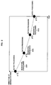
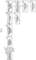
- FIG.6 is a block diagram illustrating a configuration of a radio wave arrival direction estimating antenna apparatus according to the second embodiment of the present invention.
- the radio wave arrival direction estimating antenna apparatus according to the second embodiment has basically the same configuration as that in the first embodiment.
- reference number 11 denotes an array antenna, which is provided in a base station and has a plurality of antenna elements for receiving radio waves transmitted from mobile stations.
- Reference number 12 denotes a frequency converting section which frequency-converts a received RF frequency signal received at each antenna element of array antenna 11 into a respective intermediate frequency signal.
- Reference number 13 denotes an analog-digital conversion section which converts the intermediate frequency signal into digital data.
- Reference number 14 denotes a downsampling section 13 which samples digital data from analog-digital conversion section 13 at a lower frequency.
- Reference number 15 denotes an arrival direction estimating section which estimates an arrival direction of a radio wave using digital data converted in analog-digital conversion section 13.
- Reference number 16 denotes an arrival direction tracking section which estimates a change of an arrival direction of a radio wave from a mobile station, using the estimated result in arrival direction estimating section 15 as an initial value, and digital data sampled at a lower frequency by downsampling section 14, to determine the direction sequentially.
- Reference number 17 denotes a beam forming section which directs a radiation beam of an antenna to the direction of the mobile station.
- Reference number 18 denotes a demodulating section which subjects a processed result obtained in beam forming section 17 to demodulation.
- Beam forming section 17 determines a respective weighting coefficient for a received signal at each antenna element of array antenna 11, using the estimated result in arrival direction tracking section 16, multiplies digital data subjected to the conversion at a second frequency in downsampling section 14 by the weighting coefficient, and adds all multiplied results, thereby having a function for directing the radiation beam of the antenna to the direction of the mobile station.
- reference number 61 denotes a transmission array antenna , which is provided in a base station and has a plurality of antenna elements for transmitting a transmission signal to a mobile station.
- Reference number 62 denotes a frequency conversion section which frequency-converts an analog signal into a transmission RF frequency signal to provide to array antenna 61.
- Reference number 64 denotes a transmission beam forming section which multiplies a baseband signal by a weighting coefficient corresponding to each antenna element determined by reception beam forming section 17 to generate a weighted transmission signal, and directs a radiation beam of the antenna to a direction of a mobile station.
- Reference number 63 denotes a digital-analog conversion section which converts the weighted transmission signal into an analog signal.
- Reference number 65 denotes a modulating section which generates a modulated signal of digital baseband signal to be transmitted. Further, array antenna 61 has a function for transmitting the transmission RF frequency signal.
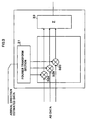
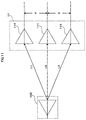
- FIG.7 is a diagram illustrating a specific example of the transmission beam forming section.
- reference numbers 71A, 71B and 71C each denotes a multiplier which multiplies modulated data by a weighting coefficient.
- a direction of a mobile station is estimated by arrival direction estimating section 15 and arrival direction tracking section 16, and based on the estimated result, a weighting coefficient is determined by beam forming section 17.
- Modulating section 65 generates a modulated signal of digital baseband signal to be transmitted to a mobile station.
- a weighted transmission signal is generated by multiplying the modulated signal by the respective weighting coefficient corresponding to each antenna element of array antenna determined by beam forming section 17 at the time of receiving.
- a modulated signal of baseband signal is subjected to the multiplication by numeric calculation in each of multipliers 71A, 71B and 71C.
- the processed result is digital data corresponding to the number of antenna elements.
- the digital data is converted into analog signals in digital-analog conversion section 63, and then converted into the transmission RF frequency signal in frequency conversion section 62.
- the transmission RF frequency signal is transmitted from transmission array antenna 61 which has the same radiation property as the reception array antenna 11, thus a radio wave is transmitted with a radiation beam of the antenna directed to a direction of a mobile station.
- array antenna 11 for receiving and transmission array antenna 61 are provided independently.
- the weighting coefficient determined in beam forming section 17 at the time of receiving is used without any processing, it is possible to form a transmission beam to a mobile station which moves at a high speed in transmission beam forming section 64, with a simple configuration. Further, by forming a transmission beam properly, it is possible to prevent the generation of interference in other base stations and mobile stations, and further to reduce transmission power to a target mobile station.
- the apparatus since the apparatus is provided with a transmission array antenna for transmitting a transmission RF frequency signal to have a reception antenna and a transmission antenna separately, the transmission can be performed without mutual interference of transmission and received signals at a RF circuit.
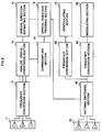
- FIG.8 is a block diagram illustrating a configuration of a radio wave arrival direction estimating antenna apparatus according to the third embodiment.
- reference number 81 denotes a sector antenna
- reference number 82 denotes an antenna switching section
- reference number 83 denotes a frequency conversion section.
- FIG.9 is a concept diagram illustrating operations of an antenna switching section.
- reference numbers 91A, 91B, 91C, 91D, 91E and 91F each denotes an antenna radiation pattern of respective antenna element of the sector antenna
- reference number 93 denotes an array antenna
- reference number 94 denotes a mobile station.
- arrival direction tracking section 16 estimates a direction of a place where a mobile station exists, and the estimated result is provided to antenna switching section 82.
- the antenna switching section 82 selects an antenna element of which the radiation pattern is a boresight to the direction of the mobile station among from antenna elements of sector antenna 81.
- sector antenna 92 is composed of six antenna elements. Each antenna element has an antenna radiation pattern capable of transmitting or receiving radio waves in a range of 60 degrees as illustrated in FIG.92A to FIG.92F.
- a direction of a mobile station is estimated based on a radio wave received at array antenna 93, and then antenna switching section 82 selects antenna element 92 A of which the boresight of the radiation pattern is directed to a direction of mobile station 94, thereby receiving/transmitting a radio wave from/to a mobile station.
- frequency conversion section 83 and frequency conversion section 62 are provided respectively for demodulation and modulation besides frequency conversion section 12.
- the apparatus since the apparatus switches a sector antenna based on a direction of a mobile station estimated in the arrival direction tracking section to perform transmission or reception, even in the case where high rate transmission is performed as compared to capable rate for digital processing, it is possible to control the antenna radiation pattern to perform data transmission with high accuracy.
- FIG.10 illustrates a configuration of a radio wave arrival direction estimating antenna apparatus according to the fourth embodiment of the present invention.
- reference number 101 denotes a phase correcting section
- reference number 102 denotes a reference transmitter.
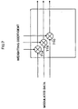
- FIG.11 illustrates a principle of phase correction.
- array antenna 11 receives a transmission test signal from reference transmitter 102 which is placed to be faced to array antenna 11.
- Each element of the array antenna has a propagation path difference due to a path length from the reference transmitter.
- FIG.11 illustrates an example in which array antenna 11 with three antenna elements receives a signal form reference transmitter 102 and performs the phase correction.
- the reference transmitter is placed in front of antenna elements 111 that is a center of the array antenna, with both faced.
- a distance between the reference transmitter and the center element of the array antenna is predetermined, and in this case, the distance is assumed as L0.
- L1 ⁇ L1 L0 ⁇ L0+d ⁇ d
- phase correction is performed using the transmission test signal from the reference transmitter, it is possible to correct shifts of amplitude and phase due to deviations of devices such as antenna elements and a RF circuit, thereby making it possible to improve an accuracy of arrival direction estimation to a high accuracy.
- an array antenna receives a signal from a reference transmitter placed to be faced to the array antenna, and the data correcting section compares a phase amplitude of digital data corresponding to each antenna element output from the analog-digital conversion section, calculates the correction value including the path difference, and adds the correction value to the digital data. Then, using the thus obtained digital data, the arrival direction estimating section and the arrival direction tracking section estimate an arrival direction, and the data correcting section corrects an error of a circuit. Therefore, it is possible to eliminate phase differences except a phase difference due to an angle of the arrival direction of a radio wave to be input to each antenna element.
- FIG.12 is a block diagram illustrating a configuration of a radio wave arrival direction estimating antenna apparatus according to the fifth embodiment.
- reference number 121 denotes a transmission data generating section
- reference number 122 denotes a mobile station
- reference number 123 denotes a demodulating section
- reference number 124 denotes an azimuth magnet
- reference number 125 denotes a base station azimuth determining section
- reference number 126 denotes an antenna
- reference number 127 denotes a notifying section.
- transmission data generating section 121 generates data indicative of an angle between the direction and, for example, "north".
- the obtained data is provided to modulation section 65 to be transmitted from transmission array antenna 61 as a transmission signal.
- base station azimuth determining section 125 determines a direction of a base station.
- Notifying section 127 notifies the determined result.
- the present invention it is possible to execute the processing in a practical time for arrival direction estimation and antenna radiation pattern control with respect to a mobile station which moves around a base station with a high speed. Therefore, it is possible to perform data transmission with high reliability, and further to reduce interference in other base stations and other mobile stations and transmission power.
Landscapes
- Physics & Mathematics (AREA)
- Engineering & Computer Science (AREA)
- General Physics & Mathematics (AREA)
- Radar, Positioning & Navigation (AREA)
- Remote Sensing (AREA)
- Mobile Radio Communication Systems (AREA)
- Radio Transmission System (AREA)
- Variable-Direction Aerials And Aerial Arrays (AREA)
Abstract
Description
Claims (11)
- A radio wave arrival direction estimating antenna apparatus comprising:an array antenna(11) having a plurality of antenna elements each for receiving a radio wave transmitted from a mobile station in a base station;frequency conversion means(12) for frequency-converting a received RF frequency signal at each antenna element of said array antenna into a respective intermediate frequency signal;analog-digital conversion means(13) for converting said intermediate frequency signal into digital data;downsampling means (14) for sampling the digital data obtained in said analog-digital conversion means at a lower frequency;arrival direction estimating means(15) for estimating an arrival direction of the radio wave using digital data converted in said analog-digital conversion means;arrival direction tracking means(16) for estimating a change of the arrival direction of the radio wave from the mobile station, using an estimated result in said arrival direction estimating means as an initial value and digital data sampled at a lower frequency in said downsampling means, to determine a direction sequentially.
- The antenna apparatus according to claim 1, further comprising reception beam forming means(17) for determining a weighting coefficient corresponding to a received signal at each antenna element, using an estimated result in said arrival direction tracking means(16), multiplying digital converted with a second frequency by said downsampling means(14) by the weighting coefficient, and adding all multiplication results, in order to direct an antenna radiation beam to a direction of the mobile station.
- The antenna apparatus according to claim 2, further comprising demodulating means(18) for demodulating using a processed result in said reception beam forming means(17).
- The antenna apparatus according to claim 2, further comprising:modulating means(65) for generating a modulated signal of a digital baseband signal to be transmitted;transmission beam forming means(64) for multiplying a baseband signal by a weighting coefficient corresponding to each antenna element determined in said reception beam forming means(17) to generate a weighted transmission signal, and directing an antenna radiation beam to the direction of the mobile station;digital-analog conversion means(63) for converting said weighted transmission signal into an analog signal; andfrequency conversion means(62) for frequency-converting said analog signal into a transmission RF frequency signal,
wherein said transmission RF frequency signal is transmitted from said array antenna. - The antenna apparatus according to claim 1, further comprising:a sector antenna comprising a plurality of antenna elements, and having radiation patterns to all directions by using all antenna elements;antenna selecting means for selecting an antenna element of said sector antenna having a radiation pattern to a direction of a place where a mobile station exists, using the estimated result in said arrival direction tracking means; anddemodulating means(18) for demodulating the intermediate frequency signal converted in said frequency conversion means,
wherein the analog-digital conversion means(13) executes conversion at a lower conversion frequency than a conversion frequency for enabling demodulation. - The antenna apparatus according to claim 4, further comprising a transmission array antenna for transmitting said transmission RF frequency signal.
- The antenna apparatus according to claim 4, further comprising a switch for switching the transmission RF frequency signal and a received RF frequency signal according to a time division.
- The antenna apparatus according to claim 1, wherein one kind of conversion frequency in said downsampling means is 1/(M+0.25) times the intermediate frequency, where M is an integer number.
- The antenna apparatus according to claim 1, wherein one kind of conversion frequency in said downsampling means is 1/(M+0.25) times the (intermediate frequency + (band width/2)), where M is an integer number, and a conversion frequency in said analog-digital conversion means is 16 times the one kind of conversion frequency.
- The antenna apparatus according to claim 1, further comprising data correcting means for comparing a phase amplitude of digital data corresponding to each antenna element, obtained in said analog-digital conversion means, calculating the correction value including a path difference, and adding said correction value to the digital data, wherein said array antenna receives a test signal from a reference transmitter faced to said array antenna, and said arrival direction estimating means and said arrival direction tracking means estimate the arrival direction, using said digital data with said correction value.
- The antenna apparatus according to claim 4, further comprising in the base station:transmission data generating means(121) for providing data indicative of an estimated direction of the mobile station to the modulating means, andfurther comprising in the mobile stationan antenna(11) for receiving a signal transmitted from the base station;demodulating means(14) for demodulating the data indicative of the estimated direction of the mobile station;an azimuth magnet(124);base station direction determining means(125) for determining a direction of a place where the base station exists using the data indicative of the estimated direction of the mobile station and the azimuth magnet;, andnotifying means(127) for notifying a determined base station direction.
Applications Claiming Priority (2)
| Application Number | Priority Date | Filing Date | Title |
|---|---|---|---|
| JP28773998A JP3985883B2 (en) | 1998-10-09 | 1998-10-09 | Radio wave arrival direction estimation antenna device |
| JP28773998 | 1998-10-09 |
Publications (3)
| Publication Number | Publication Date |
|---|---|
| EP0992813A2 true EP0992813A2 (en) | 2000-04-12 |
| EP0992813A3 EP0992813A3 (en) | 2001-10-17 |
| EP0992813B1 EP0992813B1 (en) | 2003-08-13 |
Family
ID=17721140
Family Applications (1)
| Application Number | Title | Priority Date | Filing Date |
|---|---|---|---|
| EP99119850A Expired - Lifetime EP0992813B1 (en) | 1998-10-09 | 1999-10-07 | Radio wave arrival direction estimating antenna apparatus |
Country Status (4)
| Country | Link |
|---|---|
| US (1) | US6529745B1 (en) |
| EP (1) | EP0992813B1 (en) |
| JP (1) | JP3985883B2 (en) |
| DE (1) | DE69910321T2 (en) |
Cited By (1)
| Publication number | Priority date | Publication date | Assignee | Title |
|---|---|---|---|---|
| US10405360B2 (en) | 2014-05-15 | 2019-09-03 | Huawei Technologies Co., Ltd. | Method and equipment for establishing millimetre connection |
Families Citing this family (34)
| Publication number | Priority date | Publication date | Assignee | Title |
|---|---|---|---|---|
| US8594690B2 (en) * | 2000-02-05 | 2013-11-26 | Telefonaktiebolaget L M Ericsson (Publ) | Subcell measurement procedures in a distributed antenna system |
| JP4363803B2 (en) * | 2000-08-02 | 2009-11-11 | パナソニック株式会社 | Method for exciting circular array antenna and radio apparatus using the method |
| JP3589292B2 (en) * | 2000-11-30 | 2004-11-17 | 日本電気株式会社 | Mobile communication device |
| EP1215507A3 (en) * | 2000-12-12 | 2002-08-28 | Matsushita Electric Industrial Co., Ltd. | Radio-wave arrival-direction estimating apparatus and directional variable transceiver |
| JP3888189B2 (en) * | 2002-03-12 | 2007-02-28 | 松下電器産業株式会社 | Adaptive antenna base station equipment |
| EP1392005A1 (en) * | 2002-08-13 | 2004-02-25 | Siemens Aktiengesellschaft | Method for channel estimation and corresponding radio communications system |
| WO2004082171A1 (en) * | 2003-03-11 | 2004-09-23 | Fujitsu Limited | Radio device |
| EP1564899A4 (en) * | 2003-03-31 | 2009-12-02 | Fujitsu Ltd | RECEPTION APPARATUS |
| US7050412B2 (en) * | 2003-06-23 | 2006-05-23 | Interdigital Technology Corporation | System and method for determining measurement value for radio resource management in wireless communications |
| US8073490B2 (en) * | 2003-12-19 | 2011-12-06 | Samsung Electronics Co., Ltd. | Mobile station direction finding based on observation of forward link |
| JP4805591B2 (en) * | 2005-03-17 | 2011-11-02 | 富士通株式会社 | Radio wave arrival direction tracking method and radio wave arrival direction tracking device |
| US7221318B2 (en) * | 2005-09-13 | 2007-05-22 | Kyocera Wireless Corp. | System and method for controlling antenna pattern |
| IL173069A0 (en) * | 2006-01-10 | 2006-06-11 | Zion Hadad Dr | Cellular system and method |
| KR100930049B1 (en) * | 2007-02-28 | 2009-12-08 | 삼성전자주식회사 | Beamforming Apparatus and Method Using Sector Common Antenna in Wireless Communication System |
| JP4900360B2 (en) * | 2008-10-17 | 2012-03-21 | ソニー株式会社 | Reception device, moving angle estimation method, program, and wireless communication system |
| ES2382794B1 (en) * | 2009-09-22 | 2013-05-08 | Vodafone España, S.A.U. | METHOD FOR DYNAMICALLY ESTABLISHING THE RADIATION PATTERN OF AN ANTENNA BASED ON USER EQUIPMENT POSITIONING INFORMATION |
| CN102301738B (en) | 2009-11-30 | 2015-09-30 | 松下电器(美国)知识产权公司 | Communicator |
| USRE45980E1 (en) * | 2009-11-30 | 2016-04-19 | Panasonic Intellectual Property Corporation Of America | Communication device |
| JP5558195B2 (en) * | 2010-05-07 | 2014-07-23 | 三菱重工業株式会社 | Flying object launch system |
| US9255953B2 (en) | 2012-02-16 | 2016-02-09 | Src, Inc. | System and method for antenna pattern estimation |
| CA3092509A1 (en) | 2018-03-19 | 2019-09-26 | Pivotal Commware, Inc. | Communication of wireless signals through physical barriers |
| US10522897B1 (en) | 2019-02-05 | 2019-12-31 | Pivotal Commware, Inc. | Thermal compensation for a holographic beam forming antenna |
| US10468767B1 (en) | 2019-02-20 | 2019-11-05 | Pivotal Commware, Inc. | Switchable patch antenna |
| US10734736B1 (en) | 2020-01-03 | 2020-08-04 | Pivotal Commware, Inc. | Dual polarization patch antenna system |
| US11069975B1 (en) | 2020-04-13 | 2021-07-20 | Pivotal Commware, Inc. | Aimable beam antenna system |
| KR20230017280A (en) | 2020-05-27 | 2023-02-03 | 피보탈 컴웨어 인코포레이티드 | RF signal repeater device management for 5G wireless networks |
| US11026055B1 (en) | 2020-08-03 | 2021-06-01 | Pivotal Commware, Inc. | Wireless communication network management for user devices based on real time mapping |
| US11297606B2 (en) | 2020-09-08 | 2022-04-05 | Pivotal Commware, Inc. | Installation and activation of RF communication devices for wireless networks |
| WO2022155529A1 (en) | 2021-01-15 | 2022-07-21 | Pivotal Commware, Inc. | Installation of repeaters for a millimeter wave communications network |
| WO2022164930A1 (en) | 2021-01-26 | 2022-08-04 | Pivotal Commware, Inc. | Smart repeater systems |
| US11451287B1 (en) * | 2021-03-16 | 2022-09-20 | Pivotal Commware, Inc. | Multipath filtering for wireless RF signals |
| JP2024525621A (en) | 2021-07-07 | 2024-07-12 | ピヴォタル コムウェア インコーポレイテッド | Multi-path repeater system |
| US12185453B2 (en) | 2021-10-26 | 2024-12-31 | Pivotal Commware, Inc. | RF absorbing structures |
| US11937199B2 (en) | 2022-04-18 | 2024-03-19 | Pivotal Commware, Inc. | Time-division-duplex repeaters with global navigation satellite system timing recovery |
Family Cites Families (5)
| Publication number | Priority date | Publication date | Assignee | Title |
|---|---|---|---|---|
| JP2684888B2 (en) | 1991-08-06 | 1997-12-03 | 国際電信電話株式会社 | Adaptive array antenna control method |
| US5515378A (en) | 1991-12-12 | 1996-05-07 | Arraycomm, Inc. | Spatial division multiple access wireless communication systems |
| US5815116A (en) | 1995-11-29 | 1998-09-29 | Trw Inc. | Personal beam cellular communication system |
| US5815117A (en) * | 1997-01-02 | 1998-09-29 | Raytheon Company | Digital direction finding receiver |
| US6052085A (en) * | 1998-06-05 | 2000-04-18 | Motorola, Inc. | Method and system for beamforming at baseband in a communication system |
-
1998
- 1998-10-09 JP JP28773998A patent/JP3985883B2/en not_active Expired - Fee Related
-
1999
- 1999-10-06 US US09/413,367 patent/US6529745B1/en not_active Expired - Lifetime
- 1999-10-07 DE DE69910321T patent/DE69910321T2/en not_active Expired - Lifetime
- 1999-10-07 EP EP99119850A patent/EP0992813B1/en not_active Expired - Lifetime
Cited By (1)
| Publication number | Priority date | Publication date | Assignee | Title |
|---|---|---|---|---|
| US10405360B2 (en) | 2014-05-15 | 2019-09-03 | Huawei Technologies Co., Ltd. | Method and equipment for establishing millimetre connection |
Also Published As
| Publication number | Publication date |
|---|---|
| US6529745B1 (en) | 2003-03-04 |
| JP3985883B2 (en) | 2007-10-03 |
| JP2000114849A (en) | 2000-04-21 |
| EP0992813B1 (en) | 2003-08-13 |
| DE69910321D1 (en) | 2003-09-18 |
| DE69910321T2 (en) | 2004-03-11 |
| EP0992813A3 (en) | 2001-10-17 |
Similar Documents
| Publication | Publication Date | Title |
|---|---|---|
| EP0992813B1 (en) | Radio wave arrival direction estimating antenna apparatus | |
| US7117016B2 (en) | Adaptive antenna base station apparatus | |
| US6466166B2 (en) | Multi-beam receiving apparatus | |
| US6347234B1 (en) | Practical space-time radio method for CDMA communication capacity enhancement | |
| US7088956B2 (en) | Path search circuit, radio receiver and radio transmitter, utilizing a directional beam | |
| US6415163B1 (en) | Method for transmitting pilot channels and a cellular radio system | |
| EP1361679B1 (en) | Radio communication device and arrival direction estimation method | |
| KR100426110B1 (en) | Radio communication apparatus and radio communication method | |
| KR100676034B1 (en) | Interference Reduction Method and Communication Device in Communication Device | |
| US7162210B2 (en) | Method and device of antenna pattern forming | |
| JP3600459B2 (en) | Method and apparatus for estimating direction of arrival of radio wave | |
| JP3738705B2 (en) | Adaptive antenna device | |
| US20040102157A1 (en) | Wireless LAN with distributed access points for space management | |
| US6931244B2 (en) | Radio equipment capable of real time change of antenna directivity and doppler frequency estimating circuit used for the radio equipment | |
| US6968022B1 (en) | Method and apparatus for scheduling switched multibeam antennas in a multiple access environment | |
| US7894857B2 (en) | Method including a radio transmitter for improving radio link operation | |
| US20040174300A1 (en) | Adaptive array antenna reception apparatus and method | |
| GB2380881A (en) | Estimating the angle of arrival at a mobile terminal | |
| US6118806A (en) | Signal synthesis method and apparatus under diversity reception | |
| US6990345B2 (en) | Method and apparatus for wireless position location | |
| CA2304785A1 (en) | Base station apparatus and radio communication method | |
| US6600935B1 (en) | Radio transmission device and transmission directivity adjusting method | |
| CN1784840B (en) | Adaptive antenna reception device having preferable reception quality of directivity beam from the initial stage | |
| JP2000147083A (en) | Method and apparatus for measuring arrival angle | |
| Shim et al. | Should the smart antenna be a tracking beam array or switching beam array? |
Legal Events
| Date | Code | Title | Description |
|---|---|---|---|
| PUAI | Public reference made under article 153(3) epc to a published international application that has entered the european phase |
Free format text: ORIGINAL CODE: 0009012 |
|
| AK | Designated contracting states |
Kind code of ref document: A2 Designated state(s): AT BE CH CY DE DK ES FI FR GB GR IE IT LI LU MC NL PT SE Kind code of ref document: A2 Designated state(s): DE FR GB |
|
| AX | Request for extension of the european patent |
Free format text: AL;LT;LV;MK;RO;SI |
|
| PUAL | Search report despatched |
Free format text: ORIGINAL CODE: 0009013 |
|
| AK | Designated contracting states |
Kind code of ref document: A3 Designated state(s): AT BE CH CY DE DK ES FI FR GB GR IE IT LI LU MC NL PT SE |
|
| AX | Request for extension of the european patent |
Free format text: AL;LT;LV;MK;RO;SI |
|
| RIC1 | Information provided on ipc code assigned before grant |
Free format text: 7G 01S 3/14 A, 7G 01S 3/74 B, 7H 04Q 7/36 B, 7H 04B 7/08 B, 7H 04B 7/06 B |
|
| 17P | Request for examination filed |
Effective date: 20020325 |
|
| AKX | Designation fees paid |
Free format text: DE FR GB |
|
| 17Q | First examination report despatched |
Effective date: 20020611 |
|
| GRAH | Despatch of communication of intention to grant a patent |
Free format text: ORIGINAL CODE: EPIDOS IGRA |
|
| GRAH | Despatch of communication of intention to grant a patent |
Free format text: ORIGINAL CODE: EPIDOS IGRA |
|
| GRAA | (expected) grant |
Free format text: ORIGINAL CODE: 0009210 |
|
| AK | Designated contracting states |
Designated state(s): DE FR GB |
|
| REG | Reference to a national code |
Ref country code: GB Ref legal event code: FG4D |
|
| REF | Corresponds to: |
Ref document number: 69910321 Country of ref document: DE Date of ref document: 20030918 Kind code of ref document: P |
|
| ET | Fr: translation filed | ||
| PLBE | No opposition filed within time limit |
Free format text: ORIGINAL CODE: 0009261 |
|
| STAA | Information on the status of an ep patent application or granted ep patent |
Free format text: STATUS: NO OPPOSITION FILED WITHIN TIME LIMIT |
|
| 26N | No opposition filed |
Effective date: 20040514 |
|
| REG | Reference to a national code |
Ref country code: GB Ref legal event code: 711B |
|
| REG | Reference to a national code |
Ref country code: GB Ref legal event code: 711G |
|
| REG | Reference to a national code |
Ref country code: FR Ref legal event code: RM Ref country code: FR Ref legal event code: CD |
|
| PGFP | Annual fee paid to national office [announced via postgrant information from national office to epo] |
Ref country code: DE Payment date: 20140930 Year of fee payment: 16 Ref country code: FR Payment date: 20141008 Year of fee payment: 16 Ref country code: GB Payment date: 20141001 Year of fee payment: 16 |
|
| REG | Reference to a national code |
Ref country code: DE Ref legal event code: R119 Ref document number: 69910321 Country of ref document: DE |
|
| GBPC | Gb: european patent ceased through non-payment of renewal fee |
Effective date: 20151007 |
|
| PG25 | Lapsed in a contracting state [announced via postgrant information from national office to epo] |
Ref country code: GB Free format text: LAPSE BECAUSE OF NON-PAYMENT OF DUE FEES Effective date: 20151007 Ref country code: DE Free format text: LAPSE BECAUSE OF NON-PAYMENT OF DUE FEES Effective date: 20160503 |
|
| REG | Reference to a national code |
Ref country code: FR Ref legal event code: ST Effective date: 20160630 |
|
| PG25 | Lapsed in a contracting state [announced via postgrant information from national office to epo] |
Ref country code: FR Free format text: LAPSE BECAUSE OF NON-PAYMENT OF DUE FEES Effective date: 20151102 |